

2
1. Summary
1.
Summary ....................................................................................................................................... 2
2.
Installation with wire .................................................................................................................... 3
2.1
Preliminary information ........................................................................................................ 3
2.2
Recharging base installation .................................................................................................. 4
2.2.1 Recharging base versions .......................................................................................................... 4
2.2.1.1 Recharging base without transmitter ......................................................................................... 4
2.2.1.2 Recharging base with internal transmitter ................................................................................. 5
2.2.2 Installation ................................................................................................................................. 6
2.3
Charger and transmitter installation ...................................................................................... 8
2.4
Border wire installation ......................................................................................................... 9
2.5
Return to recharging station ................................................................................................ 17
2.5.1 Return to recharging station: options ....................................................................................... 17
2.5.1.1 Return to recharging station: options available for each robot model ..................................... 18
2.5.2 Wire installation for “On bounce” and "V-meter" return options ........................................... 18
2.5.3 Return to recharging station: fast return .................................................................................. 18
2.6
Secondary areas installation ................................................................................................ 20
2.6.1 Adjacent perimeters installation .............................................................................................. 23
2.6.1.1 Example ................................................................................................................................... 24
2.6.2 Installation near to other brand robot....................................................................................... 26
2.7
Closed area installation ....................................................................................................... 27
2.8
145 model installation with guide wire to recharging station ............................................. 28
2.9
Transmitter and receiver set-up ........................................................................................... 30
2.9.1 Sinusoidal signal ...................................................................................................................... 30
2.9.1.1 Transmitter configuration ........................................................................................................ 30
2.9.1.2 Receiver configuration ............................................................................................................ 32
2.9.2 TX-S1 signal ............................................................................................................................ 32
3.
Installation without wire (robot 145 – S2) .................................................................................. 35
4.
Installation activities ................................................................................................................... 40
4.1
Pre-installation activities ..................................................................................................... 40
4.2
Post-installation activities.................................................................................................... 40
5.
Changes description ........................................................... Errore. Il segnalibro non è definito.

3
2. Installation with wire
2.1 Preliminary information
General rules and requirements for the installation of recharging base, battery charger, transmitter and border
wire are common among all the different robot models.
It is recommended to pay particular attention to properly select the appropriate model on the basis of the
characteristics of the lawn, considering the fundamental parameters reported on technical tables (see user
manual) and hereinafter described:
1. Maximum suggested lawn dimension: this is the maximum dimension (square meters) of the lawn
that the robot can manage, considering the quantity and capacity of batteries installed. In any case, it
is suggested to select a robot with a square meter capability significantly higher that lawn dimension.
In addition, remember that real coverage capability of the robot decreases if the complexity of the
garden (bumps, secondary and separated areas, etc… ) increases.
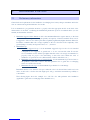
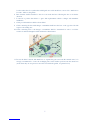
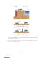
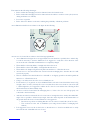
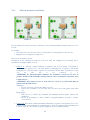
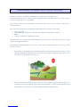
2. Maximum slope:
a. Maximum suggested slope: it is the maximum suggested slope for the robot in standard
configuration. It is suggested, as general rule, to do not overcome this value. In case the
robot is installed on areas with slopes higher than this value, it is strongly recommended to
properly verify for proper robot functioning on that areas and evaluate the need of
installation of special accessories (different kind of wheels, anti-tilt kit, etc,,,)
b. Maximum slope near the wire or external border: it is the maximum slope allowed near to
the perimeter of the lawn or near to the wire (perimeter wire or guide wire to recharging
station for 145-S2 robot model).
c. Maximum allowed slope: it is the maximum slope that the robot can manage.
Remember that the worse situation on slopes is when the robot is in descend since in this case it can
arrive on the border or border wire with high speed and go outside the lawn without possibility to
come back in.
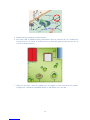
The following figure shows the example for a 145- S2 robot with perimeter wire installation
(applicable to guide wire to recharging station installation too).

4
3. Secondary areas: some robot models are able to manage a certain number of secondary areas in
addition to the primary one. Secondary area is defined as an area of the lawn that is connected to the
principal one with a corridor that is not easily reachable accidentally by the robot. See the document
“Set-up” for detailed information.
2.2 Recharging base installation
2.2.1 Recharging base versions
Robots using sinusoidal signal have the recharging base with signal transmitter that has to be located outside
the recharging base.
Robots using the new TX-S1 signal have two different models of recharging base:
• recharging base with EXTERNAL TRANSMITTER: first models of S2145 and 920 robots
• recharging base with INTERNAL TRANSMITTER: 145,125,127,325,920 - AR2400,600,1200 – S2
manufactured later than April - May 2012
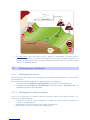
2.2.1.1 Recharging base without transmitter
The base is provided with a 6 conductors cable that ends with a white 6 poles female connector to be
connected to the signal transmitter:
• Central pins 3 and 4 are used for transmission of signal (are connected with the black and red
connectors on recharging base)
• External pins 1 and 6 are connected to the positive recharging plate
• Pins 2 and 5 are connected to the negative recharging plate

5
Following are the part numbers for connector and pins provided together with the recharging base wiring:
• 6 poles female connector
• female crimp connector
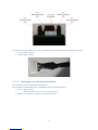
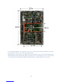
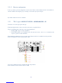
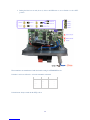
2.2.1.2 Recharging base with internal transmitter
The transmitter is located inside the recharging base.
The transmitter is embedded inside a box with the following electrical interfaces:
• Power supply connector:
o blue wire is the positive (+), brown is the negative (-)
• Black and red bushes for connection of the perimeter wire

6
In this way, power supply going to the recharging plates will no more pass through the signal transmitter,
allowing increase of recharging process efficiency (no voltage drop inside the signal transmitter board).
In this case, the recharging base will be directly connected to the battery charger by using a cable with only 2
conductors.
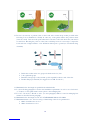
2.2.2 Installation
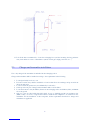
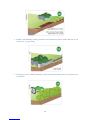
The recharging base has to be installed in accordance to the following requirements:
1. Located at the edge of the lawn, in an area with flat, stable and draining ground. The flat area shall
extend posteriorly with respect to the base for at least 1.5m (in this way, the location where the robot
synchronizes with the signal coming out from the base is located in a flat area)
2. Located so there are at least 2m of rectilinear cable before the base and at least 30cm before the first
curve in front of the base
3. Located so it does not receive water directly from irrigation system (especially from display side, for
robots provided with display)
4. It shall not be located near to an electric gate in order to avoid interference
5. It shall be well fixed to the ground. Pay attention that a step shall not be present at the entrance of the
base (step can naturally form sometime later installation time, due to traces left by the robot on the
ground). Eventually, locate a grass carpet in order to compensate the step. Another possibility is to
remove the grass from the area under the base and install the base aligned with the grass at the robot
entering side. The installation of a grass carpet on the back area of the recharging station, up to the

7
location where the robot synchronizes with signal once exit from the base, can avoid too much traces
becomes visible on the garden.
6. Base entrance shall be installed so the robot can reach the base following the wire on clockwise
direction
7. Located in a position that allows to agree with requirements related to charger and transmitter
installation
8. Cable provided with base shall not be modified
9. Cable connecting the base with charger or transmitter shall leave the base on the opposite side with
respect to the cutting area
10. Cable connecting base to the charger or transmitter shall be outstretched in order to avoid the
creation of undesired magnetic fields and therefore interferences.
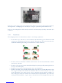
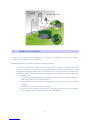
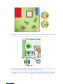
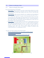
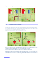
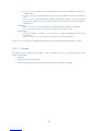
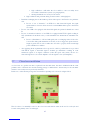
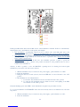
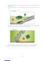
11. In case the lawn is fenced with metal bars to separate the grass area from the external areas, it is
strongly recommended to locate the recharging base in the farthest position from the metal bars
(areas where they are not present or move the base inside the garden, see picture below)

8
12. It is all the time recommended to locate the recharging base (and the incoming 2m long perimeter
wire) far from know sources of disturbances (metal, electric gates, high power lines, etc...)
2.3 Charger and transmitter installation
Note: only charger if the transmitter is embedded in the recharging station
Charger and transmitter shall be installed according to the requirements in the following:
1. Located preferably in a close room
2. If located outside, they shall be installed in a location that allows air exchange and protected from
direct sun and water
3. Located outside the garden area (area delimited by border wire)
4. Cables provided as part of charger and transmitter shall not be modified
5. Locate the items at 2-3m (80-120inc) distance from recharging station and 160cm (63inc.) minimum
above the ground
6. Only for robots provided with sinusoidal signal: in case of installation with long perimeter wire
(600m +/-20%) or in case of signal related issues, install the 48V amplifier to be connected to the
transmitter. For the installation of this component, all the requirements described for charger and
transmitter are applicable.

9
2.4 Border wire installation
After the correct location for the recharging base and charger / transmitter has been selected, it will be
possible to proceed with border wire installation.
Install the border wire in accordance with the following requirements:
1. For the first installations it is suggested to install the wire on the surface of the lawn. After some
weeks, the wire will be absorbed by the ground and grass (first weeks after installation, cutting
height shall be left higher than normal to avoid that the robot cuts the border wire). After the first
installations, thanks to acquired experience, it is suggested to use the cable layer machine and install
the wire underground.
a. If the wire is installed underground, installation deep shall be about 2-3cm (maximum 5cm).
Higher deep will cause signal level attenuation.
b. Be careful that the wire is installed straight and on curved sections it assumes a constant
curvature
c. Wire shall not be tended, coiled and corrugated
d. In case the wire is installed on lawn surface, fix it with the proper nails provided with the
robot (suggested distance between adjacent nails is 100-200cm)

10
2. Connect one side of the wire to the black bush on recharging base and exit from front side. Install
border wire to delimit garden and internal areas not to be cut. Finally enter from back side,
connecting the end of the wire to the red bush. Cable sides entering and exiting the base shall not be
crossed
3. Border wire shall be installed in the following position with respect to recharging base:
a. Centered for all robot models excluding 125 127 325 AR2400,600,1200
b. Moved to the left side of the recharging base for 125 127 325 AR2400,600,1200 robot (use
the wire guide provided on the recharging base)
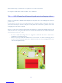
4. It is suggested to leave some stock of wire in case of need for future modifications (make a virtual
flowerbed)

11
5. Install border wire turning in clockwise direction
6. Flowerbeds shall be delimited turning anticlockwise direction (otherwise the robot identifies the
flowerbed before it is arrived on the wire and it is possible that signal problems can arise also in
areas far from the flowerbed)
7. Where it is necessary to have two parallel wires (for example to reach a flowerbed), they shall be
superimposed or installed at a maximum distance of 1cm (0.4inc) one to the other

12
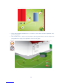
8. If there are two flowerbeds / obstacles near one to the other, it is possible to go directly from the first
to the second and come back. Parallel wires shall be installed according to point above.
9. Sidewalks located inside the garden (at the same level of the garden) or that are necessary to allow
the robot to enter / exit adjacent areas, shall not be delimited with wire
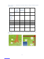
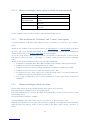
10. It is absolutely necessary to delimit all the objects both inside and outside the lawn area that can
create issues to the robot (trees with roots over ground, every element not tall enough to be detected
as a bump by the robot, etc…) or cause injury to the robot (swimming pool, hole, sudden slope

13
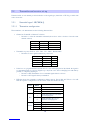
change, precipice, etc…). Install the wire around these elements according to the distances specified
in the following.
Delimited
element
Robot 145 –
S2 (used with
external
border wire)
Robot 125
127 325 AR2
400,600,1200
Robot 500, M Robot 700, Q
Sidewalk at
same level of
garden
5 5 5 5
Sidewalk at
different level
of garden
(difference
>2cm)
35 35 35 35
Wall 35 35 35 35
Hedge 35 30 30 35
Flowerbed 35 30 30 35
Drain cover 35 30 30 35
Trees with
roots over
lawn surface
35 30 30 35
Swimming
pool, hole,
precipice
70 70 70 80
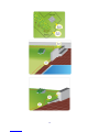
Figures in the following are only examples. For distances from delimited elements refer to the
previous table.


16
12. In case it is necessary to perform joints on the border wire, execute the procedure provided in the
following. It is recommended to identify in some way on the garden surface the positions where
joints are located. Joints are weak points where the border wire could oxide incase the joint itself is
not well done. Knowing the position of the joints could help in case it is necessary to inspect the
border wire due to high resistance or low insulation with respect to ground (see "Troubleshooting"
document)
a. Divide the conductors into two groups at both the ends to be joint
b. Join together the groups
c. Bend the joined groups so they assume a position parallel to the two ends of the wire
d. Insulate with proper material (it is suggested to use 3M “Scotch 23”)
13. Maximum border wire length is specified in the technical table
14. Look at following paragraph for border wire installation requirements in order to use “On bounce”
or "V-meter or" and “Quick return” return options to the recharging base
15. For 145 – S2 model, a “Recall on wire” (see next paragraph) shall be located at recharging base
entrance as described in next paragraph.
16. Maximum border wire length for 125 127 325 AR2400,600,1200 model is 600m
17. Maximum distance robot - wire for each good functioning of the robot is guaranteed is:
a. 60m for brushless motors robot
b. 50m for brush motors robot

17
2.5 Return to recharging station
2.5.1 Return to recharging station: options
There are three different kinds of return available:
• Return “On wire”: The robot follows the wire with one wheel inside the perimeter and one wheel
outside the perimeter. Each time the robot will return to the base, it will follow the same path (only
the wire following start point will change depending on the position of the robot on the lawn at time
of return decision).
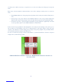
• Return “On bounce”: The robot follows a path made of arcs, touching the wire at the beginning and
at the end of each arc. Only when the robot detects a special wire shape called “Recall on wire”, it
starts to follow the wire (“On wire”) for a distance of about 14m (distance traveled on-wire can be
set using special set-up on Service Menu. See document "Robot set-up"). In case the robot does not
find the recharging station within XXX minutes driving "on-bounce", it will start automatically to
drive "on-wire", iwq6n order to reduce the risk to miss the recharging station ("recalls on wire" non
properly installed or not properly detected by the robot)
• Return "V-meter": the robot drives parallel to the border wire at a variable distance from about 10
cm to 1m. The distance from the border wire is more or less constant during the same approach,
while it changes among different approaches. As is case of "on-bounce", the robot starts driving on-
wire" after a certain time. Also in this case, in order to force the robot to drive "on-wire", it is
necessary to use the "recall on wire". There are special conditions under which the robot
automatically decides to drive "on-wire" for some meters, for example in case bumps are found
along the path when the robot is driving parallel to the wire.
“On bounce” and "V-meter" returns have the following advantages:
• Less traces on the garden since the robot does not follow every time the same path
• The recharging base is reached in less time
• Better behavior on slopes
• Less probability of blackout problems due to disturbed boundary signal
Example of “On bounce” return, robot models 500,700,M,Q

18
2.5.1.1 Return to recharging station: options available for each robot model
Robot Model Returns available
145-S2 V-meter (if updated )
125,127,325
AR2400,600,1200
V-meter (default)
On-wire
500,M On-wire (default)
On-bounce
700,Q On-wire(default)
On-bounce
See the document “Set-up” for the procedure to select the desired return options.
2.5.2 Wire installation for “On bounce” and "V-meter" return options
A special installation of the wire, called “Recall on wire” is necessary for “On bounce” and "V-meter"
return.
“Recall on wire” indicates to the robot that it is near to the recharging base or a narrow passage (from which
the robot could not pass through while making the arc or driving parallel to border wire at maximum 1m
distance from the wire) or an arrow for quick return (see next paragraph).
As soon as a recall on wire is detected by the robot, the robot will start to follow the wire “on wire” for about
14m. The robot will come back to “On bounce” or "V-meter" return if it does not enter the recharging
station.
“Recall on wire” shall be installed according to the following requirements:
• It shall have a rectangular shape. Wire shall be installed so the rectangle is 2m long and 5cm wide.
• It shall be located before the recharging base (about 4-10m).
• It shall be located before narrow passages (less than 2m) at a distance variable from 4 to 10m.
• It shall be located before arrows at a distance variable from 4 to 10m.
• It is suggested to leave a stock of wire before or after the “recall on wire” so it can be modified and /
or easily moved at the end of installation in case of need
• It is strongly recommended to test for proper identification of each "recall on wire" at the end of
installation
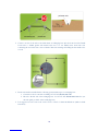
2.5.3 Return to recharging station: fast return
The fast return feature can be used with all the three return options above described.
Fast return feature is available for all robots excluding 145-S2
Fast return capability allows to decrease the length of the path that the robot has to follow in order to reach
the recharging station.
See pictured in the following for examples.
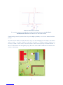
A special installation of the wire, called “Arrow”, is necessary to use the “Fast return” option.
When the robot finds the arrow along the path on the wire, it turns 90° to the right and travels until it finds
again the border wire. Then, it restarts to drive according to the desired option (on-wire, on-bounce, V-
meter).

19
Fast return has the following advantages:
• Robot reaches the recharging base in less time and causes less batteries wear.
• Robot reaches the recharging base in less time and can exit earlier to work for a new cycle (however,
during work times set on menu)
• Less traces on garden
• Robot drives less distance on the wire, reducing the probability of blackout problems.
Arrow dimensions shall be in accordance to the figure in the following.
Arrows are to be located in accordance to the following requirements:
• Arrow dimensions in figure above are approximate. In some situations, especially due to wheels slip,
it could be necessary to increase dimensions. It is suggested to verify the correct detection of the
arrows at the end of installation with batteries not completely charged
• There shall be at least 2m (80inc) of straight wire before the arrow
• There shall be at least 1.5m (60inc) of straight line after the arrow
• There shall not be bumps along the whole path from 2m before to 1.5m after the arrow
• Arrows are not to be located in the wire section before the recharging base, otherwise the robot will
never dock properly
• The robot shall not have the left wheel on a sidewalk or on slippery ground for the whole path from
2m before to 1.5m after the arrow
• Going to secondary areas, the robot does not identify arrows
• If a flowerbed (or, in general, an object delimited with border wire located inside the lawn) is big
enough to have one side (obviously the correct one) that allows the correct location of an arrow (2m
+ 1.5m straight wire), it is suggested to add the arrow so the robot can exit the wire following around
the flowerbed before than normally doing
• An arrow could be located after the recharging base so, if the robot does not dock properly, can
come back to the base directly.
• After the arrow has been detected, the robot can rotate of an angle that is not exactly the nominal 90°
angle. It is not possible to define an exact angle, since the rotation depends on the characteristics of
the ground where the arrow is located. Therefore it is suggested to:
o Decide arrow position considering that the robot can rotate not exactly 90° (about 70°-110°)
o Test each arrow at the end of installation (test using selected return to recharging base
method)
• It is suggested to leave a stock of wire before or after the arrow so it can be modified and / or easily
moved at the end of installation in case of need

20
Figures in the following provide information and suggestions useful for the correct installation of arrows.
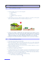
2.6 Secondary areas installation
Secondary area is defined as a part of the lawn connected to the main area by a narrow passage that could not
be accidentally reached by the robot during normal functioning (random travel) for a total number of times
necessary to allow good and efficiency mowing of secondary area.
Primary area is defined as the area where the recharging base is located.
Bigger is the primary area, higher shall be the dimension of the passage so the probability that the robot will
enter the secondary area without specific set-up from user menu of the robot is high.
Obviously, the secondary area shall be at the same level of the primary one (without steps).
If the dimension of the passage connecting the primary area to the secondary one is not big enough to allow
accidentally entrance of the robot on secondary area a number of times sufficient to allow good mowing of
La pagina si sta caricando...
La pagina si sta caricando...
La pagina si sta caricando...
La pagina si sta caricando...
La pagina si sta caricando...
La pagina si sta caricando...
La pagina si sta caricando...
La pagina si sta caricando...
La pagina si sta caricando...
La pagina si sta caricando...
La pagina si sta caricando...
La pagina si sta caricando...
La pagina si sta caricando...
La pagina si sta caricando...
La pagina si sta caricando...
La pagina si sta caricando...
La pagina si sta caricando...
La pagina si sta caricando...
La pagina si sta caricando...
La pagina si sta caricando...
La pagina si sta caricando...
-
 1
1
-
 2
2
-
 3
3
-
 4
4
-
 5
5
-
 6
6
-
 7
7
-
 8
8
-
 9
9
-
 10
10
-
 11
11
-
 12
12
-
 13
13
-
 14
14
-
 15
15
-
 16
16
-
 17
17
-
 18
18
-
 19
19
-
 20
20
-
 21
21
-
 22
22
-
 23
23
-
 24
24
-
 25
25
-
 26
26
-
 27
27
-
 28
28
-
 29
29
-
 30
30
-
 31
31
-
 32
32
-
 33
33
-
 34
34
-
 35
35
-
 36
36
-
 37
37
-
 38
38
-
 39
39
-
 40
40
-
 41
41


Global garden products Alpina AR2 400 Guida d'installazione
- Tipo
- Guida d'installazione
- Questo manuale è adatto anche per
in altre lingue
Altri documenti
-
Stiga A 1500 Manuale utente
-
STIHL RMI 422 Manuale utente
-
-
-
STIHL RMI 522.0 C Manuale utente
-
Viking MI 422 P Manuale del proprietario
-
Husqvarna AUTOMOWER 450X Manuale utente
-
-
Samsung SR20H9050U Manuale utente
-
EINHELL Expert FREELEXO 500 BT Manuale utente