
DIN-rail mounting
temperature controller with
current transformer input
D1 line
Quick Guide • 17/11 • ISTR_Q_D1_1_03_--
viale Indipendenza 56, 27029 - Vigevano (PV)
Tel.: +39 0381 698 71, Fax: +39 0381 698 730
internet site: www.ascontecnologic.com
E-mail: [email protected]
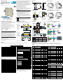
Dimensions
Terminal connectors
99 mm
3.9 in
22.5 mm
0.89 in
6.3 mm
0.25 in
114.5 mm
4.5 in
4 terminal connectors
A
B
C
D
Power supply/
comm.s
connector
Power supply voltage:
24Vac (-25...+12%) or
24Vdc (-15....+25%)
Termi-
nation
plug
Removing the instrument from the DIN rail
Switch the instrument off
12
DIN rail mounting
1
CLICK
2
1 Clip the upper part of the
instrument on the rail;
2 Rotate the instrument
downwards until the click;
1 Lower the spring slide by
inserting a flat-blade
screwdriver as indicated;
2 Turn and lift the instrument
upwards.
Parameters list
In the table that follows are listed the parameters of the controller associated to the correspondent serial ModBus address. For further
details, consult the manual: “gammadue® and deltadue® controller series Serial communications and configuration software”.
Analogue
Digital
ModBus
address
Parameter name Value
Default
Modbus
User
0 PV process variable
1SP Setpoint
2Main output
3SPT Target Setpoint
4 SPL local Setpoint
5Proportional band (PID) or
Hysteresis (ON - OFF) 5.0 or 0.5 50 or 5
6 Overshoot control 1.00 100
7Integral time 5.050
8 Derivative time 1.00 100
9Control output cycle time
(heat) 20 20
10 Low range
11 High range
12 AL2 alarm threshold 0 0
13 AL3 alarm threshold 0 0
14 AL2 alarm hysteresis 0.5 5
15 AL3 alarm hysteresis 0.5 5
16 Relative Cold Gain 1.0 10
17 Cool output Hysteresis (ON-OFF) 0.5 5
19 Heat/Cool Dead band 0.5 5
20 Cool cycle time 20 20
21 Cool output maximum value 100.0 1000
24 Timer setting 0.5 5
25 Timer Stand-by Setpoint 0 0
26 Soft-start output value 0.5 5
27 Soft-start activation time 1 1
28 Manual reset 50.0 500
29 Setpoint low limit low range
30 Setpoint high limit high range
31 Error Dead Band inhibited 0
32 Control output high limit 100.0 1000
33 Output safety value 0.0 0
34 Slope up inhibited 0
35 Slope down inhibited 0
36 Input filter inhibited 0
37 Input shift inhibited 0
ModBus
address
Parameter name Value
Default
Modbus
User
38 Start/Stop One shot tuning
(0 = stop, 1 = start) stop 0
39
Overshoot Control relative band
0.5 5.0
44 Start-up Setpoint 0 0
45 Start-Up Hold time 1 1
46
Output high limit during
Start-up
100.0 1000
47 Timer remaining time 0.5 5
49 Setpoint selection local 0
50 1st stored Setpoint
51 2nd stored Setpoint
56 AL1 alarm threshold 00
57 AL1 alarm hysteresis 0.5 5
58 AL1 latching and blocking none 0
59 AL2 latching and blocking none 0
60 AL3 latching and blocking none 0
61 LBA delay inhibited 0
62 Instrument position single 0
63 Read the first 16 coils on word
(B.O.R. = Bit On Register)
ModBus
address Parameter Value
1 Automatic/Manual 0 = Automatic, 1 = Manual
2 OP4 logical output status 0 = OFF, 1 = ON
3 OP1 digital output status 0 = OFF, 1 = ON
4 OP2 digital output status 0 = OFF, 1 = ON
5 OP3 digital output status 0 = OFF, 1 = ON
6 Out of range status 0 = Normal operation,
1 = Safety
7 Auto-Tune status 0 = Disabled, 1 = Run
8Timer function status
(if option present) 0 = OFF, 1 = Run
11 Forcing the Output status 0 = Not influenced,
1 = Forced to OFF
12 IL Digital Input status 0 = OFF, 1 = ON
13 Tune Fail status 1 = Tune failed
15 Latching alarms
acknowledgement 1 = Alarm acknowledge
Declaration of conformity and manual retrieval
D1 is a rear panel mounting, Class II instrument, it has been
designed with compliance to the European Directives.
All
information about the controller can be found in the Installation
or in
the User Manual: ISTR_I_D1_E_03_--.pdf and ISTR_U_D1_E_04_--.pdf.
The Manuals and the Declaration of Conformity of the instrument
can be downloaded (free of charge) from the web-site:
www.ascontecnologic.com
Once connected to the web-site, search:
D1
;
then click on D1
on the search result list
.
In the lower part of the product page (in any language) is present
the download area with the links to the documents available for
the requested intrument (in the available languages).
Warning!
-
Whenever a failure or a malfunction of the device may cause
dangerous situations for persons, things or animals, please
remember that the plant must be equipped with additional
devices which will guarantee safety.
-
We warrant that the products will be free from defects in
material and workmanship for 18 months from the date of
delivery. Products and components that are subject to wear
due to conditions of use, service life and misuse are not covered
by this warranty.
Disposal
The appliance (or the product) must be disposed of
separately in compliance with the local standards in
force on waste disposal.
Model code
The product code indicates the specific hardware coniguration of the instrument, that can be modified by specialized engineers only.
Configuration code
A 4 + 4 digits index code follows the model (letters from I... R).
This code can be used to buy a pre-configured controller.
[1] For instance, other thermocouples types, ΔT (with 2 PT100),
custom linearisation etc.
[2] 2 different correcting methods of the control output are availa-
ble. One for water and the other for oil:
OP water=100•(OP2/100)2 - OP oil=100•(OP2/100)1.5
Line Basic Accessories
Configuration
1st part
D1 5 B5 D-E90 0/I L M N
Model:
O P Q R
-
2nd part
Line D 1
Output OP1 - OP2 B
Relay - Not fitted 0
Relay - Relay 1
SSR - Not fitted 3
SSR - SSR 5
Options D
None 0
Current transformer (CT) 3
Special function E
Not fitted 0
Start-up + Timer 2
Input type and range I L
TR Pt100 IEC751
-99.9…300.0°C
-99.9…572.0°F
00
TR Pt100 IEC751 -200…600°C -328…1112°F 01
TC L Fe-Const DIN43710 0…600°C 32…1112°F 02
TCJ Fe-Cu45% Ni IEC584 0…600°C 32…1112°F 03
TC T Cu-CuNi -200…400°C -328…752°F 04
TC K Chromel-Alumel IEC584 0…1200°C 32…2192°F 05
TC S Pt10%Rh-Pt IEC584 0…1600°C 32…2912°F 06
TC R Pt13%Rh-Pt IEC584 0…1600°C 32…2912°F 07
TC B Pt30%Rh Pt6%Rh IEC584 0…1800°C 32…3272°F 08
TC N Nichrosil-Nisil IEC584 0…1200°C 32…2192°F 09
TC E Ni10%Cr-CuNi IEC584 0…600°C 32…1112°F 10
TC NI-NiMo18% 0…1100°C 32…2012°F 11
TC W3%Re-W25%Re 0…2000°C 32…3632°F 12
TC W5%Re-W26%Re 0…2000°C 32…3632°F 13
Dc input 0…50mV linear Engineering units 14
Dc input 10…50mVlinear Engineering units 15
Custom input range [1] 16
Control mode M
ON-OFF reverse action 0
ON-OFF direct action 1
PID single reverse action 2
PID single direct action 3
PID double action
Linear cool output 4
ON-OFF cool output 5
Water cool output 6
Oil cool output 7
Output configuration N
Single Action Double action
Relays (OP1) Heat OP1, Cool OP2 0
SSR drive (OP4) Heat OP1, Cool OP4 1
Heat OP4, Cool OP2 2
Tipo e modo di intervento allarmi O P Q
AL. 1 2 3
Disabled or used by Timer (only for AL3) 000
Sensor break/Loop Break Alarm (LBA) 111
Absolute active high 222
active low 333
Deviation active high 444
active low 555
Band active out 666
active in 777
Setpoint type R
Local only 0
Local and 2 tracking stored Setpoint 1
Local and 2 Stand-by stored Setpoint 2
Configuration and setting Software
The instrument must be configured using Controller Explorer
(a proprietary free software). The most recent release of Controller
Explorer is downloadable from our web site:
www.ascontecnologic.com
Once connected to this site, click on the banner: Download,
then click on the row: Controller Explorer.
Download the most recent version of the software and, when
present, any upgrade to the program.
Once installed the Software and the upgrades, run the program,
the default communications parameters are:
Transmission speed: 9600 bps;
Protocol: ModBus;
Serial address: 247.
Warning!
When more controllers/instruments are to be installed, keep in
mind that the default serial address always is 247.
For this reason, always connect/power on only 1 not configured
instrument a time, in order to avoid the presence, on the same
network, of 2 instruments with the same address. During the
configuration, assign to each instrument a different serial address.
The "gammadue® and deltadue® controller series Serial
communications and configuration software" manual can be
downloaded from the web site:
www.ascontecnologic.com
As for the other manuals, also this one is present in the lower part
of the product page.
Power
supply
switch
Configuration
and Supervision
NO
NO
Connections
Terminals
LL = 7 mm - 0.28 in. L = 7 mm - 0.28 in.
0.6 x 3.5 mm 0.4 x 2.5 mm
A - B - C - DFeatures Bus/Power Supply
Stripped
wire
Flat blade
screwdriver
Tightening
torque 0.5... 0.6 Nm 0.4... 0.5 Nm
Plug with termination
resistor for serial
communications bus
(male)
Connector for
power supply and
serial
communications
bus (female)
OP1
IL
RS485
24V
0... 5V
NC N
L
OP3
OP2
OP4
mA
mV
24V
24VDC
NO
Pt100
TTL
NPN
NO
Current
transformer
External
Shunt
2.5Ω
Mounting several instruments
2 Then, insert the
female 5-pole
connector with
the termination
resistor of the
serial communica-
tions
into the
corresponding
male connector;
3 Wire the 5-pole
male power
supply and serial
communications
connector and
insert it in the
corresponding
female connector;
1
Mounted the instruments on the rail, put them side by side so that the
male side connector fits into the corresponding female connector;
Connector protection
4 When assembled insert the connector protection on both sides.
12
3
4
22.5 x N + 53 mm
3
50 mm
1.969 in
Serial communications connection examples
Configuration
D1
RS485 Configuration
Cd-Rom
D1 - 31 max. instruments
Acquisition and centralized supervision
RS485
D1 - 31 max. instruments Operator panel
Local control
RS485

Regolatore di temperatura
per
guida DIN con ingresso da
trasformatore amperometrico
linea D1
Quick Guide • 17/11 • ISTR_Q_D1_1_03_--
viale Indipendenza 56, 27029 - Vigevano (PV)
Tel.: +39 0381 698 71, Fax: +39 0381 698 730
internet site: www.ascontecnologic.com
E-mail: [email protected]
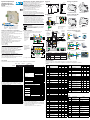
Dimensioni
Morsettiere
4 spine morsetti
Spina
alimentazione/
comunicazione
Tensione di alimentazione:
24Vac (-25...+12%) o
24Vdc (-15....+25%)
Presa
termi-
nazione
99 mm
3.9 in
22.5 mm
0.89 in
6.3 mm
0.25 in
114.5 mm
4.5 in
A
B
C
D
Rimozione dalla guida DIN
Togliere tensione allo strumento
12
Montaggio su guida DIN
1
CLICK
2
1 Agganciare la parte superiore
dello strumento sulla guida;
2 Ruotare lo strumento verso il
basso fino allo scatto;
1 Abbassare la slitta a molla
inserendo un cacciavite a lama
piatta come indicato;
2 Ruotare lo strumento verso
l’alto.
Elenco dei parametri
Nella tabella che segue sono elencati i parametri del regolatore con il relativo indirizzo seriale ModBus.
Per ulteriori informazioni si consulti il manuale: “
Configurazione e comunicazione seriale gammadue
®
e deltadue
®
”.
Analogici
Digitali
Indirizzo
ModBus
Nome parametro Valore
Default
Modbus
Utente
0Misura PV
1 Setpoint di lavoro SP
2 Uscita principale OP
3 Setpoint di target SPT
4 Setpoint locale SPL
5Banda proporzionale (PID) o
isteresi (ON - OFF) 5.0/0.5 50/5
6 Controllo Overshoot 1.00 100
7Tempo integrale 5.050
8 Tempo derivativo 1.00 100
9Tempo di ciclo uscita regolante
(caldo) 20 20
10 Inizio Scala
11 Fondo Scala
12 Soglia allarme AL2 0 0
13 Soglia allarme AL3 0 0
14 Isteresi allarme AL2 0.5 5
15 Isteresi allarme AL3 0.5 5
16
Guadagno relativo uscita Freddo
1.0 10
17 Isteresi uscita Freddo (ON-OFF) 0.5 5
19 Banda morta Caldo/Freddo 0.5 5
20 Tempo di ciclo uscita Freddo 20 20
21 Limite superiore uscita Freddo 100.0 1000
24 Tempo di esecuzione del Timer 0.5 5
25 Setpoint di Stand-by del Timer 0 0
26 Valore uscita Soft-Start 0.5 5
27 Tempo attivazione Soft-Start 1 1
28 Riassetto manuale 50.0 500
29 Limite inferiore Setpoint
inizio scala
30 Limite superiore Setpoint fine scala
31 Banda morta sull’errore esclusa 0
32 Limite superiore uscita
regolante 100.0 1000
33
Valore di sicurezza uscita
regolante
0.0 0
34 Pendenza in salita Setpoint esclusa 0
35 Pendenza in discesa Setpoint esclusa 0
36 Costante di tempo filtro misura esclusa 0
37 Correzione misura esclusa 0
38 Lancio/Arresto sintonizzazione
(0 = stop, 1 = start) stop 0
39
Banda relativa controllo
Overshoot
0.5 5.0
Indirizzo
ModBus
Nome parametro Valore
Default
Modbus
Utente
44 Setpoint di Start-up 0 0
45
Tempo di Hold durante lo Start-up
11
46 Limite superiore uscita regolante
durante lo Start-up 100.0 1000
47 Tempo residuo funzione Timer 0.5 5
48 Ampere letti dal Trasformatore
Amperometrico (TA)
49 Selezione Setpoint locale 0
50 1° Setpoint memorizzato
51 2° Setpoint memorizzato
56 Soglia allarme AL1 0 0
57 Isteresi allarme AL1 0.5 5
58 Riconoscimento e inibizione
all’accensione AL1 nessuno 0
59 Riconoscimento e inibizione
all’accensione AL2 nessuno 0
60 Riconoscimento e inibizione
all’accensione AL3 nessuno 0
61 Tempo ritardo intervento LBA escluso 0
62 Posizione strumento singolo 0
63 Lettura primi 16 coil su word
(B.O.R. = Bit On Register)
Indirizzo
ModBus Nome parametro Valore
1 Automatico/Manuale 0 = Auto,
1 = Man
2 Stato uscita logica OP4 0 = OFF, 1 = ON
3 Stato uscita OP1 0 = OFF, 1 = ON
4 Stato uscita OP2 0 = OFF, 1 = ON
5 Stato uscita OP3 0 = OFF, 1 = ON
6 Stato fuori scala 0 = Funzionamento normale,
1 = sicurezza
7 Stato Auto-Tune 0 = Inattivo,
1 = attivo
8Stato Funzione Timer
(se opzione presente)
0 = OFF,
1 = esecuzione
11 Forzatura uscite 0 = Non influenzate,
1 = forzate a OFF
12 Stato ingresso digitale IL 0 = OFF, 1 = ON
13 Stato Tune Fail 1 = tune fallito
15 Tacitazione degli allarmi in
latching 1 = tacita l’allarme
Dichiarazione di conformità e manuale istruzioni
Il D1 è uno strumento per montaggio retroquadro di Classe II
progettato per essere conforme alle Direttive europee.
Tutti i dettagli circa l’installazione e l’utilizzo dello strumento sono
inseriti nel manuale di installazione e nel manuale d’uso:
ISTR_I_D1_I_03_--.
pdf
e ISTR_U_D1_I_04_--.pdf.
I Manuali e la Dichiarazione di Conformità dello strumento
possono essere scaricati gratuitamente dal sito web:
www.ascontecnologic.com
Una volta collegato il sito internet indicato, cercare:
D1
poi selezionare D1 nell’elenco dei risultati.
Nella parte bassa della pagina dei prodotti (di qualsiasi lingua) è
presente l’area download con i collegamenti ai documenti relativi
al prodotto (nelle lingue disponibili).
Attenzione!
-
Qualora un guasto o un malfunzionamento dell'apparecchio possa
creare situazioni pericolose e/o dannose per persone, cose o
animali si ricorda che l'impianto deve essere predisposto con
dispositivi elettromeccanici aggiuntivi atti a garantire la sicurezza.
-
I prodotti sono coperti da una garanzia di 18 mesi dalla data di
spedizione. Dalla garanzia sono esclusi i prodotti e i componenti
soggetti ad usura per condizioni di utilizzo, vita utile e uso improprio.
Smaltimento
L’apparecchiatura (o il
prodotto) deve essere
oggetto di
raccolta separata in conformità alle vigenti normative
locali in materia di smaltimento.
Codice modello
La sigla del modello identifica le caratteristiche hardware del regolatore modificabili solo da personale qualificato.
Codice di configurazione
Un codice di 4 + 4 digit segue il codice modello (lettere I... R). Il codice
di configurazione serve per ordinare lo strumento preconfigurato.
[1] Esempio: altri tipi di termocoppie, ingressi non lineari
definite su specifica, ΔT (con 2 PT100) ecc.
[2] Per tener conto delle caratteristiche termiche del liquido di raf-
freddamento sono disponibili 2 metodi di correzione dell’uscita,
uno per acqua e l’altro per olio:
OP acqua = 100•(OP2/100)2 - OP olio = 100•(OP2/100)1.5
Linea Base Accessori
Configurazione
1a parte
D1 5 B5 D
-E90 0/I L M N
Modello:
O P Q R
-
2a parte
Linea D 1
Uscite OP1 - OP2 B
Relè - Non presente 0
Relè - Relè 1
SSR - Non presente 3
SSR - SSR 5
Opzioni D
Nessuna 0
Trasformatore amperometrico 3
Funzioni speciali E
Non previste 0
Start-up + Timer 2
Tipo di ingresso e campo scala I L
TR Pt100 IEC751
-99.9…300.0°C
-99.9…572.0°F
00
TR Pt100 IEC751 -200…600°C -328…1112°F 01
TC L Fe-Const DIN43710 0…600°C 32…1112°F 02
TCJ Fe-Cu45% Ni IEC584 0…600°C 32…1112°F 03
TC T Cu-CuNi -200 …400°C -328…752°F 04
TC K Chromel-Alumel IEC584
0…1200°C 32…2192°F 05
TC S Pt10%Rh-Pt IEC584 0…1600°C 32…2912°F 06
TC R Pt13%Rh-Pt IEC584 0…1600°C 32…2912°F 07
TC B Pt30%Rh Pt6%Rh IEC584 0…1800°C 32…3272°F 08
TC N Nichrosil-Nisil IEC584 0…1200°C 32…2192°F 09
TC E Ni10%Cr-CuNi IEC584 0…600°C 32…1112°F 10
TC NI-NiMo18% 0…1100°C 32…2012°F 11
TC W3%Re-W25%Re 0…2000°C 32…3632°F 12
TC W5%Re-W26%Re 0…2000°C 32…3632°F 13
Ingresso lineare 0…50mV In unità ingegneristiche 14
Ingresso lineare 10…50mV In unità ingegneristiche 15
Ingresso e scala “custom” [1] 16
Tipo di regolazione M
ON-OFF ad azione inversa 0
ON-OFF ad azione diretta 1
PID ad azione singola inversa 2
PID ad azione singola diretta 3
PID a doppia azione
Uscita Freddo lineare 4
Uscita Freddo ON-OFF 5
Uscita Freddo per acqua [2] 6
Uscita Freddo per olio [2] 7
Tipo di uscita N
Azione singola Doppia azione
Relè (OP1) Caldo OP1, Freddo OP2 0
Logica (OP4) Caldo OP1, Freddo OP4 1
Caldo OP4, Freddo OP2 2
Tipo e modo di intervento allarmi O P Q
AL. 1 2 3
Disabilitato o utilizzato dal Timer (solo AL3) 000
Rottura sensore/Loop break alarm (LBA) 111
Assoluto attivo alto 222
attivo basso 333
In deviazione attivo alto 444
attivo basso 555
Di banda attivo fuori 666
attivo dentro 777
Heater Break da trasf.
amperometrico
attivo nel periodo ON dell’uscita
888
attivo nel periodo OFF dell’uscita
999
Tipo di Setpoint R
Solo locale 0
Locale + 2 Setpoint memorizzati con tracking 1
Locale + 2 Setpoint memorizzati di Stand-by 2
Software di configurazione e impostazione
Lo strumento deve essere configurato mediante il software Controller
Explorer (programma proprietario gratuito).
La versione più recente del programma Controller Explorer può essere
scaricata dal sito internet:
www.ascontecnologic.com
Collegato il sito internet indicato selezionare: Download
poi cliccare sulla riga: Controller Explorer.
Effettuare il download della versione più recente del programma
più gli eventuali aggiornamenti.
Una volta installato il software e gli aggiornamenti, lanciare il
programma, i parametri di comunicazione di default sono:
Velocità di trasmissione: 9600 bps;
Protocollo: ModBus;
Indirizzo seriale: 247.
Attenzione!
Quando si devono installare più strumenti, porre attenzione al
fatto che l'indirizzo seriale di default è sempre = 247.
Per questa ragfione, alimentare o collegare sempre 1 strumento
per volta in modo da non avere attivi sulla stessa rete 2
strumenti con lo stesso indirizzo seriale.
Assegnare indirizzi diversi ad ogni strumento.
Il manuale "Configurazione e comunicazione seriale
gammadue® e deltadue®" può essere scaricato dal sito:
www.ascontecnologic.com
Come per gli altri manuali, anche quello indicato è presente nella
parte bassa della pagina specifica del prodotto.
Trasformatore
amperometrico
Morsetti
LL = 7 mm - 0.28 in. L = 7 mm - 0.28 in.
0.6 x 3.5 mm 0.4 x 2.5 mm
A - B - C - DCaratteristica Bus/Alimentazione
Filo
spelato
Cacciavite
a taglio
Coppia di
serraggio 0.5... 0.6 Nm 0.4... 0.5 Nm
Interruttore
alimentazione
Configurazione
e Supervisione
Spina bus
alimentazione
e linea seriale
(femmina)
Presa con
resistenza di
terminazione
linea seriale
(maschio)
Shunt
esterno
2.5Ω
Collegamenti
NA
NA
OP1
IL
RS485
24V
0... 5V
NC N
L
OP3
OP2
OP4
mA
mV
24V
24VDC
NA
Pt100
TTL
NPN
NA
Installazioni multiple
2 Dopo aver affiancato
tutti gli strumenti
inserire la spina
femmina a 5 poli
con resistenza di
terminazione della
linea seriale
nel
corrispondente
maschio;
3 Cablare il connettore
di alimentazione
sulla spina maschio
a 5 poli ed inserirla
nella corrispondente
femmina;
1
Dopo aver montato gli strumenti sulla guida, affiancarli in modo che il
connettore trasversale si inserisca nel connettore corrispondente;
12
3
4
22.5 x N + 53 mm
protezione connettori
3
4 A montaggio ultimato inserire le protezioni connettori su ambo i lati.
50 mm
1.969 in
Esempi di collegamento seriale
Configurazione
D1
RS485 CD-ROM con tool
di configurazione
D1 - 31 strumenti max.
Acquisizione e comando centralizzato
RS485
D1 - 31 strumenti max. Pannello operatore
Controllo locale
RS485
-
 1
1
-
 2
2

