KTM 64112955044 Manuale del proprietario
- Tipo
- Manuale del proprietario

3.213.816
64112955044
LOW CHASSIS KIT
06.2019
INFORMATION
KTM Sportmotorcycle GmbH
5230 Mattighofen, Austria
www.ktm.com
*3213816*

2
Le agradecemos que se haya decidido por este producto.
Este producto de alta calidad está probado para la competición y se ha desarrollado específi camente para las exigencias de este deporte. Para poder garantizar
los máximos niveles de seguridad y funcionalidad, es imprescindible que el producto se monte correctamente. Por este motivo, es muy importante que siga las
instrucciones del manual de montaje o que se ponga en contacto con su concesionario autorizado.
El (cuasi) fabricante y el proveedor de este producto no se harán responsables del montaje y el uso incorrectos.
¡Muchas gracias!
Wir freuen uns, dass Sie sich für dieses Produkt entschieden haben.
Unser hochwertiges Qualitätsprodukt ist rennerprobt und wurde speziell für sportliche Herausforderungen entwickelt. Eine korrekte Montage des Produktes
ist unerlässlich, um ein Maximum an Sicherheit und Funktionalität gewährleisten zu können. Bitte befolgen Sie daher die Montageanleitung oder wenden Sie
sich an Ihren autorisierten Fachhändler.
Für falsche Montage oder Verwendung dieses Produktes kann der (Quasi-)Hersteller bzw. Lieferant nicht zur Verantwortung gezogen werden.
Vielen Dank.
Thank you for choosing this product.
Our high quality product has been tested under racing conditions and was developed specifi cally for use in sports activities. Correct installation of the product
is essential to ensure that a maximum degree of safety and functionality is achieved. Therefore, please follow the installation instructions or contact your
authorized dealer.
The (quasi) manufacturer or supplier cannot be held responsible for products that are incorrectly mounted or inappropriately used.
Thank you.
Grazie per aver scelto questo prodotto.
Questo nostro prodotto di pregiata qualità è collaudato nelle competizioni ed è stato sviluppato specifi camente per gare sportive. Il montaggio corretto del prodotto
è fondamentale per garantirne la massima sicurezza e funzionalità. Rispetti quindi le istruzioni di montaggio o rivolgersi al proprio concessionario autorizzato.
Il produttore (detentore del marchio)/fornitore non può essere considerato responsabile per un montaggio o impiego errato del presente prodotto.
Vi ringraziamo per l’attenzione!
Merci d‘avoir porté votre choix sur ce produit.
Notre produit de haute qualité est éprouvé pour les compétitions et a été conçu spécialement pour un usage sportif. Un montage approprié du produit est
indispensable pour garantir une sécurité et une fonctionnalité maximales du véhicule. C‘est pourquoi nous vous invitons à suivre scrupuleusement le manuel
de montage ou à vous adresser à votre revendeur agréé.
En cas de montage ou d‘utilisation non conformes de ce produit, le (quasi) constructeur ou le fournisseur déclinent toute responsabilité.
Merci !
15 ITALIANO
21 FRANÇAIS
27 ESPAÑOL
3 DEUTSCH
9 ENGLISH

3
DEUTSCH
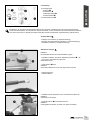
Lieferumfang
1x Tieferlegungskit
2x Buchse
2x Distanzring
1x Befestigungskopf
1x Distanzscheibe
1x Seitenständer kurz
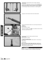
Vorarbeit Gabel
- Kotfl ügel vorn ausbauen (s. Reparaturanleitung).
- Motorrad mit Montageständer aufheben (s. Reparaturanleitung).
- Gabelbeine ausbauen (s. Reparaturanleitung).
Gabelbeine zerlegen
HINWEIS
Die Arbeitsschritte sind an beide Gabelbeinen gleich.
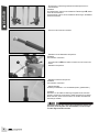
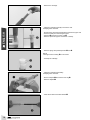
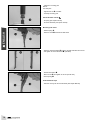
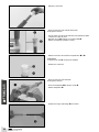
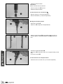
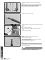
- Gabelbein im Bereich der oberen Gabelbrücke (Abstand = 25
mm) in einen Schraubstock einspannen.
Klemmblock T612S
- Schraubdeckel lösen.
HINWEIS
Der Schraubdeckel kann noch nicht abgenommen werden.
- Gabel ausspannen.
- Gabelöl entleeren.
- Gabelbein mit der Gabelfaust in den Schraubstock einspannen.
HINWEIS
Schonbacken verwenden.
- Schraube Patrone mit Scheibe entfernen.
HINWEIS
Auff anggefäß unterstellen, da meist noch etwas Öl ausläuft.
Alle Arbeiten, die mit diesem Symbol gekennzeichnet sind, erfordern Fachkenntnisse und technisches Verständnis.
Lassen Sie diese Arbeiten, im Interesse Ihrer eigenen Sicherheit, in einer autorisierten KTM-Fachwerkstatt durchführen!
Dort wird Ihr Motorrad von speziell geschulten Fachkräften mit dem erforderlichen Spezialwerkzeug optimal betreut.

4
DEUTSCH
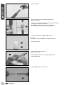
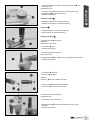
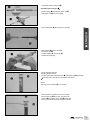
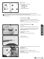
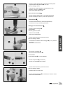
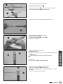
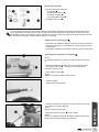
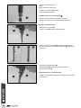
- Patrone entfernen.
- Patrone senkrecht in den Schraubstock einspannen.
Klemmblock T14015S
- Feder nach unten ziehen und Spezialwerkzeug (Gabelschlüssel
T14032) auf den Sechskant schieben.
- Mutter gegenhalten und Schraubdeckel entfernen.
- Spezialwerkzeug (Gabelschlüssel T14032) entfernen.
- Feder mit Vorspannbuchsen und entfernen.
HINWEIS
Die große 30 mm Buchse wird nicht wieder verwendet.
- Patrone ausspannen.
- Patrone waagerecht einspannen.
Klemmblock T14015S
- Adapter eindrücken und Sicherungsring entfernen.
- Adapter entfernen.
- Hydrostop abdrehen und entfernen.

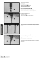
5
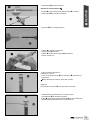
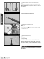
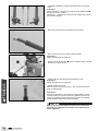
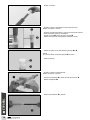
- Kolbenstange komplett entfernen.
Gabelbeine zusammenbauen
- Buchse (Lieferumfang) auf der Kolbenstange montieren.
- Kolbenstange in die Patrone schieben.
- Hydrostop auf Anschlag montieren.
- Adapter in die Patrone schieben.
- Sicherungsring montieren.
- Adapter auf dem Sicherungsring positionieren.
- Patrone ausspannen.
- Patrone senkrecht einspannen.
Klemmblock T14015S
- Feder mit Vorspannbuchsen und Distanzring (Lieferumfang)
positionieren.
Enge Wicklung der Feder ist nach unten montiert.
HINWEIS
Die große 30 mm Buchse wird nicht wieder verwendet.
- Spezialwerkzeug (Gabelschlüssel T14032) montieren.
- Schraubdeckel auf Anschlag montieren.
- Mutter gegenhalten und Schraubdeckel mit 30 Nm festziehen.
- Spezialwerkzeug (Gabelschlüssel T14032) entfernen.
DEUTSCH

6
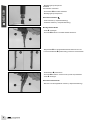
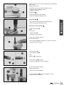
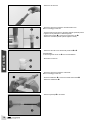
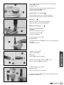
- Entsprechend zusammengehörende Einzelkomponenten zu-
sammenbauen.
HINWEIS
Druckstufenseite: Patrone mit zusätzlichen Ölbohrungen , Gabel-
faust mit Kennzeichen L.
Zugstufenseite: Patrone ohne zusätzliche Ölbohrungen, Gabelfaust
mit Kennzeichen R.
- Patrone in das Innenrohr schieben.
- Gabelbein mit der Gabelfaust einspannen.
HINWEIS
Schonbacken verwenden.
- Schraube Patrone mit Scheibe montieren und mit 25 Nm fest-
ziehen.
- Gabelbein ausspannen.
- Gabelbein senkrecht einspannen.
HINWEIS
Schonbacken verwenden.
- Gabelöl einfüllen.
Gabelöl pro Gabelbein = 470 ml Gabelöl (SAE 4) (48601166S1)
HINWEIS
Nachdem ca. die Hälfte der Ölmenge eingefüllt wurde, Schraub-
deckel in Außenrohr einschrauben, Gabel ausspannen und einige
Male einfedern, damit sich die Patrone mit Öl füllt. Anschließend
Restmenge einfüllen.
Verwenden Sie nur Öle, welche den angegebenen Normen ent-
sprechen (siehe Angaben auf dem Behälter) und die entspre-
chenden Eigenschaften besitzen.
DEUTSCH

7
Nacharbeit Gabel
- Gabelbeine einbauen (s. Reparaturanleitung).
- Kotfl ügel vorn einbauen (s. Reparaturanleitung).
Federbein
- Federbein ausbauen (s. Reparaturanleitung).
- Feder ausbauen (s. Reparaturanleitung).
Montage Federbein
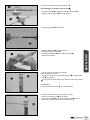
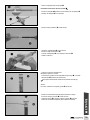
- Befestigungskopf einspannen.
HINWEIS
Schonbacken verwenden.
- Kontermutter lösen.
- Federbein ausspannen.
- Federbein senkrecht einspannen.
Klemmblock T535
- Befestigungskopf ggf. erwärmen (50° C), abdrehen und entfernen.
- Federbein ausspannen.
- Kontermutter entfernen.
- Distanzring entfernen.
HINWEIS
Distanzring wird nicht wieder verwendet.
- Distanzscheibe (Lieferumfang) montieren.
- Kontermutter auf Anschlag montieren.
- Federbein senkrecht einspannen.
Klemmblock T535
- Gewinde mit Loctite 2701 sichern.
- Befestigungskopf (Lieferumfang) montieren und mit 75 Nm
festziehen.
- Federbein ausspannen.
DEUTSCH
- Gabelbein im Bereich der oberen Gabelbrücke (Abstand = 25
mm) einspannen.
Klemmblock T612S
- O-Ring des Schraubdeckels schmieren (Schmiermittel T158).
- Schraubdeckel mit 40 Nm festziehen.
- Gabelbein ausspannen.

8
- Befestigungskopf einspannen.
HINWEIS
Schonbacken verwenden.
- Kontermutter mit 20 Nm festziehen.
- Befestigungskopf ausspannen.
Nacharbeit Federbein
- Feder einbauen (s. Reparaturanleitung).
- Federbein einbauen (s. Reparaturanleitung).
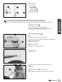
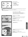
Montage Seitenständer
- Feder aushängen.
- Schraube entfernen und Seitenständer abnehmen.
- Magnethalter vom Original-Seitenständer entfernen und am
kurzen Seitenständer (Lieferumfang) montieren und festziehen.
- Seitenständer positionieren.
- Schraube montieren und mit 35 Nm (Loctite 243) festziehen.
- Feder einhängen.
Nacharbeit Seitenständer
- Motorrad vom Montageständer nehmen (s. Reparaturanleitung).
DEUTSCH

9
Scope of supply
1x low chassis kit
2x bushing
2x spacer ring
1x mounting part
1x spacer washer
1x side stand, short
Fork preparatory work
- Remove the front fender (see repair manual).
- Raise the motorcycle with a lift stand (see repair manual).
- Remove the fork legs (see repair manual).
Disassembling the fork legs
NOTE
The operations are the same on both fork legs.
- Clamp the fork leg in the area of the upper triple clamp (distance
= 25 mm) in a bench vise.
Clamping block T612S
- Loosen screw cap .
NOTE
The screw cap cannot be removed yet.
- Unclamp the fork.
- Drain the fork oil.
- Clamp the fork leg with the fork shoe in the bench vise.
NOTE
Use soft jaws.
- Remove cartridge screw with the washer.
NOTE
Place a container underneath as oil will run out in most cases.
ENGLISH
All work marked with this symbol requires specialist knowledge and technical understanding.
In the interest of your own safety, have these jobs performed by an authorized KTM workshop.
There, your motorcycle will be optimally cared for by specially trained experts using the auxiliary tools required.

10
- Remove the cartridge.
- Clamp the cartridge vertically in the bench vise.
Clamping block T14015S
- Pull the spring downward and slide the special tool (open end
wrench T14032) onto the hexagonal part.
- Hold nut and remove screw cap .
- Remove special tool (open end wrench T14032).
- Remove spring with preload spacers and .
NOTE
The large 30 mm bushing is not reused.
- Unclamp the cartridge.
- Clamp the cartridge horizontally.
Clamping block T14015S
- Press in adapter and remove lock ring .
- Remove adapter .
- Twist off and remove the fl uid barrier .
ENGLISH

11
ENGLISH
- Completely remove piston rod .
Assembling the fork legs
- Mount bushing (included) on piston rod .
- Slide piston rod into the cartridge.
- Mount fl uid barrier all the way up to the stop.
- Slide adapter into the cartridge.
- Mount lock ring .
- Position adapter on lock ring .
- Unclamp the cartridge.
- Clamp cartridge vertically.
Clamping block T14015S
- Position spring with preload spacers and spacer ring (included).
The tight coil of the spring is mounted at the bottom.
NOTE
The large 30 mm bushing is not reused.
- Mount special tool (open end wrench T14032).
- Mount screw cap all the way up to the stop.
- Hold nut and tighten screw cap with 30 Nm.
- Remove special tool (open end wrench T14032).

12
- Assemble the individual components that belong together.
NOTE
Compression damping side: Cartridge with additional oil holes ,
fork shoe marked L.
Rebound damping side: Cartridge without additional oil holes, fork
shoe marked R.
- Slide the cartridge into the inner fork tube.
- Unclamp the fork leg with the fork shoe.
NOTE
Use soft jaws.
- Mount cartridge screw with the washer and tighten to 25 Nm.
- Unclamp the fork leg.
- Clamp the left fork leg vertically.
NOTE
Use soft jaws.
- Fill with the fork oil.
Fork oil per fork leg = 470 ml of fork oil (SAE 4) (48601166S1)
NOTE
After approx. half the oil capacity has been fi lled, close the screw
cap of the outer fork tube, unclamp the fork and bounce a number
of times so that the cartridge fi lls with oil. Then add the remaining
amount.
Use only oils that comply with the specifi ed standards (see
specifi cations on the container) and that have the correspond-
ing properties.
ENGLISH

13
Fork rework
- Mount fork legs (see Repair Manual).
- Install front fender (see repair manual).
Shock absorber
- Remove the shock absorber (see the repair manual).
- Remove spring (see the repair manual).
Mounting the shock absorber
- Clamp mounting part .
NOTE
Use soft jaws.
- Loosen lock nut .
- Unclamp the shock absorber.
- Clamp shock absorber vertically.
Clamping block T508S
- Heat mounting part if required (50 °C), twist off and remove.
- Unclamp the shock absorber.
- Remove lock nut .
- Remove spacer ring .
NOTE
Spacer ring is not reused.
- Mount spacer disk (included).
- Mount lock nut all the way up to the stop.
- Clamp shock absorber vertically.
Clamping block T508S
- Secure thread with Loctite 2701.
- Mount mounting part (included) and tighten to 75 Nm.
- Unclamp the shock absorber.
ENGLISH
- Clamp the fork leg in the area of the upper triple clamp (distance
= 25 mm).
Clamping block T612S
- Grease the O-ring of the screw cap (lubricant T158)
- Tighten the screw cap with 40 Nm.
- Unclamp the fork leg.

14
- Clamp the mounting part.
NOTE
Use soft jaws.
- Tighten lock nut to 20 Nm.
- Unclamp mounting part.
Shock absorber rework
- Fit spring (see repair manual)
- Fit shock absorber (see repair manual)
Mounting side stand
- Detach spring .
- Remove screw and take off side stand.
- Remove magnetic holder from the original side stand and mount
and tighten on short side stand (included).
- Position side stand .
- Mount screw and tighten to 35 Nm (Loctite 243).
- Attach spring .
Side stand fi nal steps
- Take the motorcycle off of the lift stand (see Repair Manual).
ENGLISH

15
Materiale fornito
1 kit di ribassamento della ciclistica
2 boccole
2 anelli distanziali
1 testa di fi ssaggio
1 spessore
1 cavalletto laterale corto
Lavori preliminari forcella
- Smontare il parafango anteriore (v. manuale di riparazione).
- Sollevare la motocicletta con un cavalletto alzamoto (v. manuale di
riparazione).
- Smontare le gambe della forcella (v. manuale di riparazione).
Smontaggio delle gambe della forcella
AVVERTENZA
La procedura è identica per entrambe le gambe della forcella.
- Serrare in una morsa la gamba della forcella in corrispondenza
della piastra superiore della forcella (distanza = 25 mm).
Blocco di serraggio T612S
- Svitare il coperchio a vite .
AVVERTENZA
Il coperchio a vite non può ancora essere estratto.
- Sbloccare la forcella.
- Scaricare l’olio della forcella.
- Serrare nella morsa la gamba della forcella con il mozzo del perno
della ruota anteriore.
AVVERTENZA
Utilizzare ganasce morbide.
- Rimuovere la vite della cartuccia con la rondella.
AVVERTENZA
Posizionare al di sotto il contenitore di recupero, poiché quasi sem-
pre fuoriesce ancora dell’olio.
ITALIANO
Tutti i lavori contrassegnati con questo simbolo richiedono competenze tecniche e comprensione della materia.
Per la vostra sicurezza, far eseguire questi interventi presso un’offi cina autorizzata KTM
che si occuperà della vostra moto in modo ottimale, impiegando manodopera specializzata ed addestrata e con i necessari
utensili speciali.

16
- Rimuovere la cartuccia.
- Serrare la cartuccia in posizione verticale nella morsa.
Blocco di serraggio T14015S
- Tirare la molla verso il basso e spingere l’utensile speciale (chiave
inglese T14032) sull’inserto a testa esagonale.
- Tenere fermo il dado e rimuovere il coperchio a vite .
- Rimuovere l’utensile speciale (chiave inglese T14032).
- Rimuovere la molla con le bussole di precarico e .
AVVERTENZA
La boccola grande da 30 mm non verrà riutilizzata.
- Sbloccare la cartuccia.
- Serrare la cartuccia in posizione orizzontale.
Blocco di serraggio T14015S
- Premere l’adattatore e rimuovere l’anello di sicurezza .
- Rimuovere l’adattatore .
- Svitare l’hydrostop e rimuoverlo.
ITALIANO

17
- Rimuovere completamente l’asta del pistone .
Riassemblaggio delle gambe della forcella
- Montare la boccola (in dotazione) sull’asta del pistone .
- Spingere l’asta del pistone dentro la cartuccia.
- Montare l’hydrostop fi no a battuta.
- Spingere l’adattatore dentro la cartuccia.
- Montare l’anello di sicurezza .
- Posizionare l’adattatore sull’anello di sicurezza .
- Sbloccare la cartuccia.
- Serrare la cartuccia in posizione verticale.
Blocco di serraggio T14015S
- Posizionare la molla con le bussole di precarico e l’anello distan-
ziale (in dotazione).
L’avvolgimento stretto della molla è montato rivolto verso il basso.
AVVERTENZA
La boccola grande da 30 mm non verrà riutilizzata.
- Montare l’utensile speciale (chiave inglese T14032).
- Montare il coperchio a vite fi no a battuta.
- Tenere fermo il dado e serrare il coperchio a vite a 30 Nm.
- Rimuovere l’utensile speciale (chiave inglese T14032).
ITALIANO

18
- Riassemblare opportunamente tra loro i singoli componenti.
AVVERTENZA
Lato registro di compressione: cartuccia con fori dell’olio supple-
mentari, mozzo del perno della ruota anteriore con contrassegno L.
Lato registro di estensione: cartuccia senza fori dell’olio supplemen-
tari, mozzo del perno della ruota anteriore con contrassegno R.
- Spingere la cartuccia dentro il tubo interno della forcella.
- Serrare la gamba della forcella con il mozzo del perno della ruota
anteriore.
AVVERTENZA
Utilizzare ganasce morbide.
- Montare la vite della cartuccia con la rondella e serrare a 25 Nm.
- Sbloccare la gamba della forcella.
- Serrare la gamba della forcella in posizione verticale.
AVVERTENZA
Utilizzare ganasce morbide.
- Immettere l’olio della forcella.
Olio della forcella per ogni gamba della forcella = 470 ml (SAE 4)
(48601166S1)
AVVERTENZA
Dopo aver versato circa metà della quantità d’olio, avvitare il co-
perchio a vite nel tubo esterno della forcella, sbloccare la forcella
e aff ondare alcune volte in modo che la cartuccia si riempia d’olio.
Versare quindi il quantitativo restante.
Utilizzare solo oli conformi alle normative indicate (vedi i dati
riportati sul serbatoio) e aventi le proprietà corrispondenti.
ITALIANO

19
ITALIANO
Lavori conclusivi forcella
- Montare le gambe della forcella (v. manuale di riparazione).
- Montare il parafango anteriore (v. manuale di riparazione).
Ammortizzatore
- Smontare l’ammortizzatore (v. manuale di riparazione).
- Smontare la molla (v. manuale di riparazione).
Montaggio dell’ammortizzatore
- Serrare la testa di fi ssaggio .
AVVERTENZA
Utilizzare ganasce morbide.
- Svitare il controdado .
- Sbloccare l’ammortizzatore.
- Serrare l’ammortizzatore in posizione verticale.
Blocco di serraggio T508S
- Eventualmente scaldare la testa di fi ssaggio (50 °C), svitarla e
rimuoverla.
- Sbloccare l’ammortizzatore.
- Rimuovere il controdado .
- Rimuovere l’anello distanziale .
AVVERTENZA
L’anello distanziale non verrà riutilizzato.
- Montare lo spessore (in dotazione).
- Montare il controdado fi no a battuta.
- Serrare l’ammortizzatore in posizione verticale.
Blocco di serraggio T508S
- Fissare il fi letto con Loctite 2701.
- Montare la testa di fi ssaggio (in dotazione) e serrarla a 75 Nm.
- Sbloccare l’ammortizzatore.
- Serrare la gamba della forcella in corrispondenza della piastra
superiore della forcella (distanza = 25 mm).
Blocco di serraggio T612S
- Lubrifi care l’O-ring del coperchio a vite (lubrifi cante T158).
- Serrare il coperchio a vite a 40 Nm.
- Sbloccare la gamba della forcella.

20
- Serrare la testa di fi ssaggio.
AVVERTENZA
Utilizzare ganasce morbide.
- Serrare il controdado a 20 Nm.
- Sbloccare la testa di fi ssaggio.
Lavori conclusivi ammortizzatore
- Montare la molla (v. manuale di riparazione).
- Montare l’ammortizzatore (v. manuale di riparazione).
Montaggio cavalletto laterale
- Sganciare la molla .
- Rimuovere la vite e il cavalletto laterale.
- Rimuovere il supporto a magnete dal cavalletto laterale origi-
nale, montarlo sul cavalletto laterale corto (in dotazione) e
serrare.
- Posizionare il cavalletto laterale .
- Montare la vite e serrarla a 35 Nm (Loctite 243).
- Agganciare la molla .
Lavoro conclusivo cavalletto laterale
- Togliere la motocicletta dal cavalletto alzamoto (v. manuale di
riparazione).
ITALIANO
La pagina si sta caricando...
La pagina si sta caricando...
La pagina si sta caricando...
La pagina si sta caricando...
La pagina si sta caricando...
La pagina si sta caricando...
La pagina si sta caricando...
La pagina si sta caricando...
La pagina si sta caricando...
La pagina si sta caricando...
La pagina si sta caricando...
La pagina si sta caricando...
-
 1
1
-
 2
2
-
 3
3
-
 4
4
-
 5
5
-
 6
6
-
 7
7
-
 8
8
-
 9
9
-
 10
10
-
 11
11
-
 12
12
-
 13
13
-
 14
14
-
 15
15
-
 16
16
-
 17
17
-
 18
18
-
 19
19
-
 20
20
-
 21
21
-
 22
22
-
 23
23
-
 24
24
-
 25
25
-
 26
26
-
 27
27
-
 28
28
-
 29
29
-
 30
30
-
 31
31
-
 32
32


KTM 64112955044 Manuale del proprietario
- Tipo
- Manuale del proprietario
in altre lingue
- français: KTM 64112955044 Le manuel du propriétaire
- español: KTM 64112955044 El manual del propietario
- Deutsch: KTM 64112955044 Bedienungsanleitung
Documenti correlati
-
KTM 63612955044 Manuale del proprietario
-
-
KTM 93312955033 Manuale del proprietario
-
-
-
-
-