
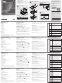
Description de l’appareil
A
Vue avant
1. Poignée
2. Bouton coulissant d'ouverture
3. Écran LCD
4. Commandes LCD
5. Commutateurs de ports
6. Voyants des ports
7. Clavier
8. Pavé tactile
9. Voyant d'alimentation
10. Supports de fi xation pour montage sur rack
11. Voyants de verrouillage
12. Bouton de réinitialisation
13. Section de mise à niveau du microprogramme
14. Eclairage LED
Vue arrière
1. Port de connexion en chaîne
2. Section des ports KVM
3. Prise d'alimentation
4. Bouton de mise sous/hors tension
* Les panneaux avant et arrière du CL1016 sont similaires. En
revanche, le CL1008 ne possède qu'une rangée de voyants (à
l'avant) et une rangée de ports UC (à l'arrière).
CL1008/CL1016 LCD KVM Switch Quick Start Guide
Hardware Review
A
Front View
1. Handle
2. Slide Release
3. LCD Display
4. LCD Controls
5. Port Switches
6. Port LEDs
7. Keyboard
8. Touchpad
9. Power LED
10. Rack Mounting Brackets
11. Num Lock LEDs
12. Reset Switch
13. Firmware Upgrade Section
14. LED Illumination Light
Rear View
1. Daisy Chain Port
2. KVM Port Section
3. Power Socket
4. Power Switch
* The front and rear panel views are similar for the CL1016, the
difference being that the CL1008 has only one row of LED lights
(front) and one row of KVM ports (rear)
System Requirements:
Computers
The following equipment must be installed on each computer:
• A VGA, SVGA or Multisync card.
• 6-pin mini-DIN (PS/2 style) keyboard and mouse ports.
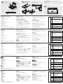
Hardware Installation:
B
Standard Rack Mounting
The standard rack mount kit enables the switch to be mounted in rack
with a depth of 42.0 - 82.0 cm.
B-1
1. While one person positions the switch in the rack and holds it in
place, the second person loosely screws the front brackets to the
rack.
B-2
2. While the fi rst person still holds the switch in place, the second
person slides the L brackets into the switch's side mounting
brackets from the rear until the bracket fl anges contact the rack,
then screws the L brackets to the rack.
B-3
3. After the L brackets have been secured, tighten the front bracket
screws.
Note:
• It takes two people to mount the switch: one to hold it in place; the
other to screw it in.
• Optional mounting kits – including single person Easy Installation
kits – are available with a separate purchase.
Single Stage Installation
1. Use a KVM cable set to connect any available KVM Port to the
computer's keyboard, video and mouse ports.
2. Plug the power cord into the CL1008 / CL1016's power socket and
into a AC power source.
Operation
C
OSD Port Selection
All procedures start from the OSD Main screen. To pop up the Main
Screen, tap the [Scroll Lock] key twice.To bring the KVM focus to a
port, Double Click it, or move the Highlight Bar to it then press [Enter].
Hotkey Port Selection
All hotkey operations begin by invoking hotkey mode (HKM):
1. Press and hold down the [Num Lock] key
2. Press and release the [minus] key
3. Release the [Num Lock] key
The minus key must be released within one half second otherwise
Hotkey invocation is canceled.
Hotkey Summary
[Num
Lock]
+ [-]
[Port ID]
[Enter]
Switches the KVM focus to the computer that
corresponds to that Port ID. The port ID corresponds
to the KVM port number that the computer is
connected to (1-16)
[A]
Invokes Auto Scan Mode.
• When Auto Scan Mode is in effect, [P] or Left Click
pauses Auto Scanning.
• When Auto Scanning is paused, pressing P or Left
Clicking again resumes Auto Scanning.
Note: Pressing almost any of the typewriter keys
(letters, numbers, Enter, Esc, Spacebar, etc.), will
resume scanning.
[←]
Skips from the current port to the fi rst accessible
port previous to it.
[→]
Skips from the current port to the next accessible
port.
[↑]
Skips from the current port to the last accessible port
of the previous Station. If you are at a port on the
First Station you cycle backward to the last accessible
port on the Last Station.
[↓]
Skips from the current port to the fi rst accessible
port of the next Station. If you are at a port on the
Last Station you cycle forward to the fi rst accessible
port on the First station.
[B]
Toggles the Beeper On or Off.
Guise de mise en route du commutateur KVM LCD CL1008/CL1016
CL1008/CL1016 LCD-KVM-Switch Kurzanleitung
Conmutador KVM con pantalla LCD CL1008/CL1016 Guía rápida
L Brackets
Side Mountng
Brackets
Phillips I head
M4 x 6
Confi guration système:
Ordinateurs
Les composants suivants doivent être installés sur chaque ordinateur :
• Une carte VGA, SVGA ou Multisync.
• Des ports clavier et souris (PS/2) mini-DIN à 6 broches.
Installation du matériel
B
Montage sur rack standard
Le kit de montage sur rack standard permet de monter le
commutateur sur rack, avec une profondeur de 42 à 82 cm.
B-1
1. Pendant qu'une première personne positionne le commutateur
dans le rack et le maintient en place, une deuxième visse les
supports avant sur le bâti.
B-2
2 Pendant que la première personne maintient toujours en place le
commutateur, la deuxième fait glisser les supports en L dans les
supports de montage latéraux du commutateur, à l'arrière, jusqu'à
ce que les brides des supports entrent en contact avec le bâti, puis
visse les supports en L sur le bâti.
B-3
3. Une fois les supports en L sécurisés, serrez les vis des supports
avant.
Remarque :
• Deux personnes sont nécessaires pour monter le commutateur : une
pour le tenir en place et l’autre pour le visser.
• Des kits de montage en option, y compris des kits faciles à installer
par une seule personne, sont disponibles séparément.
Installation simple
1. Utilisez un jeu de câbles KVM pour relier un port KVM disponible
aux ports clavier, vidéo et souris de l'ordinateur.
2. Branchez le cordon d'alimentation sur la prise d'alimentation du
CL1008 / CL1016 et sur une prise secteur.
Fonctionnement
C
Sélection de ports à l'aide du menu OSD
Toutes les procédures s'effectuent à partir de l'écran principal de
l'OSD. Pour affi cher l'écran principal, appuyez deux fois sur la touche
[Arrêt défi l].
Pour activer le contrôle KVM sur un port particulier, double-cliquez
dessus ou positionnez-y la barre en surbrillance et appuyez sur [Entrée].
Sélection de ports à l'aide des raccourcis clavier
Pour utiliser les raccourcis clavier, vous devez activer le mode de
raccourcis clavier (HKM) :
1. Appuyez sur la touche Verr num et maintenez-la enfoncée.
2. Appuyez sur la touche Moins [-], puis relâchez-la.
3. Relâchez la touche Verr num.
Vous devez relâcher la touche [-] en moins d'une demi-seconde afi n
de ne pas désactiver le mode de raccourcis clavier.
Récapitulatif des raccourcis clavier
[Verr num] +
[-]
[ID de port]
[Entrée]
Centre l'activité KVM sur l'ordinateur
correspondant à cet ID de port. L'ID de port
correspond au numéro de port KVM auquel est
connecté l'ordinateur (1 à 16).
[A]
Active le mode de recherche automatique.
• Lorsque la recherche automatique est
activée, appuyez sur [P] ou cliquez avec le
bouton gauche de la souris pour suspendre la
recherche.
• Lorsque la recherche automatique est
suspendue, appuyez de nouveau sur [P] ou
cliquez avec le bouton gauche de la souris
pour reprendre la recherche.
Remarque : vous pouvez appuyer sur
pratiquement toutes les touches
du clavier (lettres, chiffres, Entrée,
Échap, barre d'espace, etc.) pour
reprendre la recherche.
[←]
Passe du port actuel au premier port précédent
accessible.
[→]
Passe du port actuel au premier port suivant
accessible.
[↑]
Passe du port actuel au dernier port accessible
de la station précédente. Si vous êtes sur un
port de la première station, vous êtes renvoyé
au dernier port accessible de la dernière station.
[↓]
Passe du port actuel au premier port accessible
de la station suivante. Si vous êtes sur un port
de la dernière station, vous passez au premier
port accessible de la première station.
[B]
Active ou désactive le bip sonore.
Hardwareübersicht
A
Vorderseitige Ansicht
1. Griff
2. Ausziehentriegelung
3. LCD-Display
4. LCD-Bedienelemente
5. Portumschalter
6. Port-LEDs
7. Tastatur
8. Touchpad
9. LED-Betriebsanzeige
10. Schienen für die Rackmontage
11. Verriegelungs-LEDs
12. Schalter zum Zurücksetzen
13. Abschnitt zur Firmwareaktualisierung
14. LED-Beleuchtung
Rückseitige Ansicht
1. Port für Reihenschaltung
2. KVM-Portabschnitt
3. Netzeingangsbuchse
4. Netzschalter
* Die vorder- und rückseitigen Ansichten des CL1016 sind ähnlich,
der Unterschied liegt darin, dass der CL1008 nur eine Reihe LED-
Anzeigen (Vorderseite) und eine Reihe KVM-Ports (Rückseite) besitzt.
Systemvoraussetzungen:
Computer
Für jeden Computer muss Folgendes installiert werden:
• Eine VGA-, SVGA- oder Multisync-Grafi kkarte
• 6-polige Mini-DIN-Tastatur- und Mausports (PS/2)
Hardware installieren:
B
Standard-Rack-Montage
Mit dem Standard-Rack-Montagekit können Sie den Switch in ein
Rack mit einer Tiefe von 42,0 -82,0 cm einbauen.
B-1
1. Während die eine Person den Switch in den Rack schiebt und
festhält, setzt die zweite Person die Schrauben lose auf die
Montageschienen.
B-2
2. Während die erste Person den Switch nach wie vor festhält,
schiebt die zweite die L-Schienen von hinten auf die seitlichen
Montagerahmen des Switches, bis der Flansch den Rack berührt.
Schrauben Sie die L-Schienen anschließend am Rack fest.
B-3
3. Nachdem Sie die L-Schienen befestigt haben, ziehen Sie auch die
Schrauben an der Vorderseite fest.
Hinweis:
• Zur Montage des Switches sind zwei Personen erforderlich: eine
zum Festhalten und die andere zum Verschrauben der Einheit.
• Optionale Montagekits – darunter auch solche, die durch eine
Einzelperson installiert werden können – sind optional erhältlich.
Einzelinstallation
1. Verbinden Sie die Tastatur-, Maus- und Monitoranschlüsse des
Computers mit einem freien KVM-Anschluss am Gerät. Verwenden
Sie dazu ein KVM-Kabelset.
2. Verbinden Sie das Netzkabel mit der Stromeingangsbuchse, dem
CL1008 / CL1016 und dem Steckdose.
Bedienung
C
KVM-Portauswahl per OSD-Menü
Alle Funktionen werden über das OSD-Menü aufgerufen. Um das
OSD-Hauptmenü zu öffnen, drücken Sie zweimal die Taste [Rollen].
Um die KVM-Funktionen auf einen Port umzuschalten, doppelklicken
Sie auf ihn, oder bewegen Sie den Markierungsbalken hierauf und
betätigen die Taste [Enter].
KVM-Portauswahl per Hotkey
Für die Bedienung über Hotkey-Tasten müssen Sie zunächst den
Hotkey-Modus (HKM) aktivieren.
1. Halten Sie die Taste Num gedrückt.
2. Drücken Sie die Taste Minus, und lassen Sie sie los.
3. Lassen Sie die Taste Num los.
Sie müssen die Taste Minus innerhalb einer halben Sekunde los lassen.
Anderenfalls wird der Hotkey-Betrieb deaktiviert.
Hotkey-Übersicht
[Num] + [- ]
[Port-ID]
[Enter]
Schaltet die KVM-Steuerung auf den Computer um,
der an diesen Port angeschlossen ist. Die Port-ID
entspricht der Nummer des KVM-Ports, an den der
Computer angeschlossen ist (1 bis 16).
[A]
Startet die automatische Umschaltung.
• Sie können die automatische Umschaltung durch
Drücken der Taste [P] oder klicken mit der linken
Maustaste vorübergehend anhalten.
• Ist die automatische Umschaltung angehalten,
können Sie sie durch Drücken der Taste P bzw.
Klicken mit der linken Maustaste fortsetzen.
Hinweis: Sie können auch fast alle
Schreibmaschinentasten (Buchstaben,
Ziffern, Enter, Esc, Leertaste usw.) drücken,
um die Umschaltung fortzusetzen.
[←]
Springt vom aktuellen Port zum nächstmöglichen
vorigen Port, der verfügbar ist.
[→]
Springt vom aktuellen Port zum nächstmöglichen
Port, der verfügbar ist.
[↑]
Um vom aktuellen Port zum letztmöglichen Port der
vorigen Station zu springen. Falls Sie bereits einen
Port auf der ersten Station verwenden, springen Sie
zum letzten verfügbaren Port der letzten Station
zurück.
[↓]
Um vom aktuellen Port zum erstmöglichen Port der
nächsten Station zu springen. Falls Sie bereits einen
Port auf der letzten Station verwenden, springen
Sie zum ersten verfügbaren Port der ersten Station
zurück.
[B]
Schaltet die Tonsignale ein bzw. aus.
Presentación del hardware
A
Vista frontal
1. Asa
2. Desbloqueo retráctil
3. Pantalla LCD
4. Controles LCD
5. Conmutadores de puertos
6. Indicadores LED de los puertos
7. Teclado
8. Panel táctil
9. Indicador LED de alimentación
10. Raíles para montaje en rack
11. Indicadores LED de bloqueo
12. Interruptor de reseteo
13. Sección para actualizaciones del fi rmware
14. Iluminacion LED
Vista posterior
1. Puerto para conexión en margarita
2. Sección de puertos KVM
3. Entrada de alimentación
4. Interruptor de alimentación
* Los paneles anterior y posterior del CL1016 son similares, la única
diferencia es que el CL1008 sólo posee una hilera de indicadores LED
(delante) y una hilera de puertos para KVM (detrás).
Requisitos del sistema
Ordenadores
En cada ordenador se tienen que instalar los siguientes componentes:
• Una tarjeta gráfi ca VGA, SVGA o Multisync
• Puertos para teclado y ratón (PS/2) mini-DIN de 6 patillas
Instalación del hardware
B
Montaje en rack estándar
Con el kit de montaje en rack estándar puede montar el equipo en un
rack con una profundidad entre 42,0 y 82,0 cm.
B-1
1. Mientras una persona coloca el conmutador en el rack y lo aguanta
en su sitio, una segunda atornilla (sin apretar) la parte frontal de los
raíles en el rack.
B-2
2. Mientras la primera persona sigue aguantando el conmutador, la
segunda desliza los raíles en L sobre el conmutador desde la parte
trasera hasta que la pestaña del soporte haga contacto con el rack
y luego atornilla los raíles en L al rack.
B-3
3. Cuando tenga los raíles en L atornillados, apriete también los
tornillos frontales de los raíles.
Nota:
• Hacen falta dos personas para instalar el concentrador: una que lo
coloca en su sitio y la otra que lo atornilla.
• Existen kits de montaje opcionales – incluyendo kits de montaje para
una sola persona.
Instalación individual
1. Use un juego de cables KVM para conectar cualquier puerto
KVM disponible a los puertos para teclado, monitor y ratón del
ordenador.
2. Enchufe el cable de alimentación a la entrada de alimentación del
CL1008 / CL1016 y a una toma eléctrica.
Funcionamiento
C
Selección de puertos mediante el menú OSD
Todos los procedimientos tienen su origen en la pantalla principal del
OSD. Para acceder a la pantalla principal, pulse dos veces la tecla [Bloq
Despl].
Para llevar el control KVM a un puerto, haga doble clic en él o
desplace la barra resaltada sobre él y pulse [Intro].
Selección de puertos mediante teclas de acceso directo
Todas las operaciones relacionadas con teclas de acceso directo
requieren que primero cambie al modo de teclas de acceso directo
(HKM):
1. Mantenga pulsada la tecla Bloq Num.
2. Pulse la tecla Menos [-] y suéltela.
3. Suelte la tecla Bloq Num.
Debe soltar la tecla Menos dentro de un tiempo de medio segundo.
De lo contrario, las teclas de acceso directo se desactivan.
Resumen de las teclas de acceso directo
[Bloq Num]
+ [- ]
[ID del
puerto]
[Intro]
Da el control KVM al ordenador al que le corresponde
el ID de puerto seleccionado. El identifi cador de
puerto corresponde al número de puerto KVM al que
el ordenador está conectado (1 a 16).
[A]
Activa el modo de conmutación automática.
• Pulse la tecla [P] o haga clic con el botón izquierdo
del ratón para detener la conmutación automática
temporalmente.
• Pulse de nuevo la tecla [P] o haga clic con el botón
izquierdo del ratón para reanudar la conmutación
automática.
Nota: puede pulsar casi cualquier tecla del teclado
(letras, números, Intro, Esc, Espacio, etc.) para
reanudar la conmutación automática.
[←]
Salta al primer puerto anterior accesible a partir del
puerto actual.
[→]
Salta al puerto siguiente accesible a partir del puerto
actual.
[↑]
Para pasar del puerto actual al último puerto accesible
de la estación anterior.. Si ya utiliza un puerto de
la primera estación, retrocederá al último puerto
accesible de la última estación.
[↓]
Para pasar del puerto actual al primer puerto accesible
de la estación siguiente. Si ya utiliza un puerto de la
última estación, pasará al primer puerto accesible de
la primera estación.
[B]
Activa o desactiva las señales acústicas.
B-1
B-2
B-3
LCD KVM Switch
Quick Start Guide
CL1008 / CL1016
Package Contents
1 CL1008/CL1016 with Standard Rack Mount Kit
2 Custom KVM Cable Sets
1 Power Cord
1 Firmware Upgrade Cable
1 User Instructions
www.aten.com
www.aten.com
www.aten.com
www.aten.com
© Copyright 2019 ATEN
®
International Co., Ltd.
ATEN and the ATEN logo are trademarks of ATEN International Co., Ltd. All rights reserved. All
other trademarks are the property of their respective owners.
This product is RoHS compliant.
Part No. PAPE-1223-384G Printing Date: 06/2019
Hardware Review
Operation
Hardware Installation
Single Stage Installation
Standard Rack Mounting
Support and Documentation Notice
All information, documentation, fi rmware,
software utilities, and specifi cations contained in
this package are subject to change without prior
notifi cation by
the manufacturer.
To reduce the environmental impact of our
products, ATEN documentation and software can
be found online at
http://www.aten.com/download/
Technical Support
www.aten.com/support
이 기기는 업무용(A급) 전자파적합기기로서 판매자 또는 사용자는 이 점을 주의
하시기 바라며, 가정외의 지역에서 사용하는 것을 목적으로 합니다.
Scan for
more information
EMC Information
FEDERAL COMMUNICATIONS COMMISSION INTERFERENCE STATEMENT:
This equipment has been tested and found to comply with the limits for a
Class A digital device, pursuant to Part 15 of the FCC Rules. These limits
are designed to provide reasonable protection against harmful interference
when the equipment is operated in a commercial environment. This
equipment generates, uses, and can radiate radio frequency energy and,
if not installed and used in accordance with the instruction manual, may
cause harmful interference to radio communications. Operation of this
equipment in a residential area is likely to cause harmful interference in
which case the user will be required to correct the interference at his own
expense.
FCC Caution: Any changes or modifi cations not expressly approved by
the party responsible for compliance could void the user's authority to
operate this equipment.
Warning: Operation of this equipment in a residential environment could
cause radio interference.
This device complies with Part 15 of the FCC Rules. Operation is subject
to the following two conditions: (1) this device may not cause harmful
interference, and (2) this device must accept any interference received,
including interference that may cause undesired operation.
Important. Before proceeding, download the Installation and Operation Manual by
visiting the website, www.aten.com and navigating to the product page. The manual
includes important warnings, loading specifi cations and grounding instructions.
A
Front View
Rear View
B
C
F1:GOTO F3:SET F5:SKP F7:SCAN X
F2:LIST F4:ADM F6:BRC F8:LOUT
z
z
z
ADMINISTRATOR
LIST:ALL
SN PN QV NAME
01 14 ATEN INTL.CO. 1
01 15 ATEN INTL.CO. 2
01 16 ATEN INTL.CO. 3
02 01 FAX SERVER 1
02 02 FAX SERVER 2
02 03 WEB SERVER 1
02 04 WEB SERVER 2
02 05 MAIL SERVER 1
1
2
3
4
1 2
3 4
1
2
1
EXIT I LIGHT
Press the Exit/Light pushbutton
for two seconds to turn the
LED light ON or Off. (Default: On)
4
1
2
2
3
9
8
5
6
11
12
13
14
7
8
&
&

CL1008/CL1016 LCD KVM Switch - Guida rapida
CL1008/CL1016 LCD KVMスイッチクイックスタートガイド
CL1008/CL1016 LCD KVM 스위치 빠른 사용 가이드
CL1008/CL1016 LCD KVM 切换器快速安装卡
CL1008/CL1016 LCD KVM
A
B
C
F1:GOTO F3:SET F5:SKP F7:SCAN X
F2:LIST F4:ADM F6:BRC F8:LOUT
z
z
z
ADMINISTRATOR
LIST:ALL
SN PN QV NAME
01 14 ATEN INTL.CO. 1
01 15 ATEN INTL.CO. 2
01 16 ATEN INTL.CO. 3
02 01 FAX SERVER 1
02 02 FAX SERVER 2
02 03 WEB SERVER 1
02 04 WEB SERVER 2
02 05 MAIL SERVER 1
Presentación del hardware
A
Vista frontale
1. Maniglia
2. Sganciamento della slitta retraibile
3. Display a cristalli liquidi
4. Comandi LCD
5. Pulsanti di selezione della porta
6. LED della porta
7. Tastiera
8. Touchpad
9. LED di alimentazione
10. Staffe per il montaggio in rack
11. LED di blocco
12. Interruttore di ripristino
13. Sezione per l’aggiornamento del firmware
14. Illuminazione LED
Lato posteriore
1. Porta in cascata
2. Sezione porta KVM (Porta KVM)
3. Presa di alimentazione
4. Interruttore di alimentazione
* I pannelli anteriore e posteriore del CL1016 sono simili e differiscono
solo per il fatto che il CL1008 è dotato di una sola fila di LED
(anteriore) ed una sola fila di porte per la KVM (posteriore)
Requisiti di sistema:
Computer
In ogni computer deve essere installato il seguente equipaggiamento:
• una scheda VGA, SVGA o Multisync
• Porte per tastiera e mouse 6-pin mini-DIN (stile PS/2).
Installazione hardware
B
Montaggio in rack standard
Il kit standard di montaggio su rack consente il montaggio dello switch
su rack con una profondità di 42,0 - 82,0 cm.
B-1
1. Mentre una persona posiziona lo switch nel rack e lo mette in
posizione, la seconda persona fissa provvisoriamente i supporti
frontali al rack.
B-2
2. Mentre la prima persona continua a tenere in posizione lo switch, la
seconda fa scivolare i supporti a L nei supporti laterali di montaggio
dello switch, partendo dal retro, fino a quando non sono a stretto
contatto con il rack e poi, utilizzando le viti in dotazione al kit, avvita
i supporti a L al rack.
B-3
3. Una volta fissati i supporti a L, stringere le viti dei supporti
anteriori.
Nota:
• Per montare lo switch sono necessarie due persone: una per tenerlo
fermo in posizione, l’altra pere avviatarlo.
• I kit di montaggio opzionali – compresi i kit d’installazione facile per
una sola persona – sono disponibili in vendita separatamente.
Installazione singola
1. Usare un set di cavi KVM per connettere qualsiasi porta
KVM disponibile alle porte della tastiera, video e mouse del
computer.
2. Inserire la spina del cavo di alimentazione nella presa di
alimentazione del CL1008 / CL1016 e in una fonte di
alimentazione CA.
Funzionamento
C
Sezione delle porte OSD
Tutte le procedure partono dalla schermata OSD principale. Per
accedere alla schermata principale, premere due volte il tasto [Bloc
Scorr].
Per selezionare una porta per il KVM, fare doppio clic su essa o
evidenziarla e premere [Invio].
Sezione della porta tramite i tasti di scelta rapida
Tutte le operazioni con i tasti di scelta rapida iniziano con la selezione
della Modalità tasti di scelta rapida (HKM):
1. Premere e tenere premuto il tasto Bloc Num.
2. Premere e rilasciare il tasto ‘meno’
3. Rilasciare il tasto Bloc Num
Il tasto meno deve essere rilasciato entro mezzo secondo, in caso
contrario il richiamo del tasto di scelta rapida viene annullato.
Hotkey Summary
[Bloc
Num] +[-]
[ID della
porta]
[Invio]
Cambia la concentrazione KVM al computer
corrispondente a quel ID di porta L'identificativo di
porta corrisponde al numero di porta della KVM al
quale è connesso il computer (1-16)
[A]
Richiama la modalità Scansione automatica
• Quando la modalità Scansione automatica è attiva,
premendo [P] o facendo clic con il tasto sinistro del
mouse si mette in pausa tale modalità
• Quando la scansione automatica viene messa in
pausa, la pressione di P o fare clic con il tasto sinistro
del mouse riavvia la scansione automatica.
Nota: La pressione di qualsiasi dei tasti della macchina
da scrivere (lettere, numeri, Invio, Esc, barra
spaziatrice ecc), riavvia la scansione
[
←
]
Passa dalla porta corrente alla prima porta accessibile
precedente.
[
→
]
Passa dalla porta corrente alla prima porta accessibile
successiva.
[
↑
]
Salta dalla porta corrente all'ultima porta accessibile
della stazione precedente. Se ci si trova a una porta
della prima stazione, si ritorna indietro all’ultima porta
accessibile dell’ultima stazione.
[
↓
]
Salta dalla porta corrente alla prima porta accessibile
della stazione successiva. Se ci si trova a una porta
dell’ultima stazione, si ritorna indietro alla prima porta
accessibile della prima stazione.
[B] Attiva e disattiva il segnale acustico
製品各部名称
A
フロントビュー
1. ハンドル
2. スライド固定スイッチ
3. LCDディスプレイ
4. LCDコントロール
5. ポートスイッチ
6. ポートLED
7. キーボード
8. タッチパッド
9. 電源LED
10.ラックマウントブラケット
11.NumLockLED
12.リセットスイッチ
13.ファームウェアアップグレードセクション
14.LEDライト
リアビュー
1. デイジーチェーンポート
2. KVMポートセクション
3. 電源ソケット
4. 電源スイッチ
*CL1016のフロントパネル及びリアパネルの外観は上図とほぼ同じです。
異なる点は、フロントパネルのLEDとリアパネルのKVMポートがCL1008
は1列だけとなっていることです。
必要ハードウェア環境:
コンピューター
各コンピューターには以下が必要です:
•
VGA,SVGAまたはMultisyncビデオカード
•
6ピンミニDIN(PS/2)キーボード及びマウスポート
ハードウェアセットアップ
B
標準ラックマウント
標準ラックマウントキットを使用して、奥行きが42.0-82.0cmのラックに
スイッチを据え付けることができます。
B-1
1.作業する1人は、システムラックの取り付け位置付近でスイッチを保持し
てください。作業する2人目が、スイッチフロント側のブラケットをラッ
クに仮止めしてください。
B-2
2.作業する1人は取り付け位置付近でスイッチを保持したままにしてくださ
い。作業する2人目はスイッチリア側から製品同梱のL字ブラケットをス
ライドさせて取り付け、ブラケットをラックにネジ止めしてください。
B-3
3.L字金具のネジ止めが完了したら、仮止めしたフロントパネルのネジをし
っかりと締めてください。
注意:
•
標準ラックマウントキットを使用してのマウント作業は、必ず2人以上で
作業してください。
•
1人で作業可能なイージーセットアップラックマウントキットは、ユーザ
ー選択のオプションとなっています。
単体でのインストール
1.KVMケーブルを使用して、空いているKVMポートとコンピューターの
キーボード、モニター、マウスの各ポートを接続してください。
2.電源ケーブルをCL1008/CL1016の電源ソケットに接続した後、電源コ
ンセントに接続してください。
操作方法
C
OSDでのポートセレクト
OSDを使用するには、まずOSDメイン画面を開きます。メイン画面を開く
には[ScrollLock]キーを2回押します。
KVMポートを選択するには、選択したいポートをダブルクリックするか、
またはハイライトバーでそのポートを選択した後、[Enter]キーを押しま
す。
ホットキーでのポートセレクト
ホットキーを使用するにはまずホットキーモード(HKM)を起動させま
す:
1.〔NumLock〕キーを押したまま
2.〔-〕マイナスキーを押して離します。
3.最後に〔NumLock〕キーを離します。
マイナスキーは0.5秒以内に離さないと、ホットキーモードがキャンセルさ
れてしまいますのでご注意ください。
ホットキー一覧表
[Num
Lock]+[-]
[ポー
トID]
[Enter]
使用したいポートIDのコンピューターへとKVMフォー
カスを切り替えます。ポートIDとはコンピューターが
接続されたNo.1-16のKVMポート番号のことです。
[A]
オートスキャンモードを起動します。
•
オートスキャンモードが起動中に、[P]を押すか、ま
たはマウスを左クリックしてオートスキャンを一時停
止できます。
•
オートスキャンが一時停止している際に、再度[P]を
押すか、またはマウスを左クリックすれば、オートス
キャンを再開します。
注意:文字、数字、Enter、Esc、スペースキー等のほ
とんどのキー入力でもオートスキャンを再開する
ことができます。
[←]
現在のポートからひとつ前のアクセス可能なポートへ
と切り替わります。
[→]
現在のポートから次のアクセス可能なポートへと切り
替わります。
[↑]
現在のポートからひとつ前のステーションの最後のア
クセス可能なポートへと切り替わります。1段目のステ
ーションのポートを使用している場合は、最後のステ
ーションのポートへと切り替わります。
[↓]
現在のポートから次のステーションの最初のアクセス
可能なポートへと切り替わります。最後のステーショ
ンのポートを使用している場合は、最初のステーショ
ンのアクセス可能なポートへと切り替わります。
[B] ブザー音のOn/Oを切り替えます。
하드웨어 리뷰
A
정면도
1. 손잡이
2. 슬라이드 해제
3. LCD 디스플레이
4. LCD 컨트롤
5. 포트 스위치
6. 포트 LED
7. 키보드
8. 터치패드
9. 전원 LED
10. 랙 마운팅 브라켓
11. Num Lock LED
12. 리셋 스위치
13. 펌웨어 업그레이드 부분
14. LED 불빛
후면도
1. 데이지 체인 포트
2. KVM 포트부분
3. 전원 소켓
4. 전원 스위치
* 정면도와 후면도는CL1016와 같지만, CL1008는 LED등(정면)과 KVM포
트(후면)가 한 줄로 되어 있다. 必要ハ
ー
ドウェア環境:
시스템 요구사항:
컴퓨터
각 컴퓨터에는 다음의 장비가 반드시 설치 되어 있어야 한다. :
• VGA, SVGA 또는 멀티씽크 카드.
• 6-핀 미니-딘(PS/2 스타일) 키보드 및 마우스 포트.
하드웨어 설치 방법
B
표준 랙 마운팅
표준 랙 마운트 킷은 랙의 42.0 - 82.0 cm사이에 설치 할 수 있다.
C-1
1. 한 사람은 랙 안의 스위치를 고정하여 잡고, 다른 사람은 정면 브라켓에
서 랙으로 느슨하게 나사를 조이십시오.
C-2
2. 먼저 한 사람이 스위치를 잡고 있고, 다른 사람은 L 브라켓을 뒤에서 브라
켓 프렌지가 랙에 닿을 때까지 스위치의 옆쪽 마운팅 브라켓으로 삽입하
신 후 L 브라켓을 랙에 고정하십시오.
C-3
3. L 브라켓을 고정 후, 앞쪽 브라켓의 나사를 확실히 고정시킨다.
주의:
• 설치 시 두 명이 함께 설치한다. 한 명은 장비를 랙의 설치 하고자 하는 부
분에 고정하고 다른 한 명은 나사를 랙에 고정한다.
• 옵션 마운팅 킷- 일인 설치용 킷은 별도로 구매 할 수 있음.
단일 스테이지 설치 방법
1. KVM 케이블 세트를 사용하여 컴퓨터와 연결한다.
2. 파워 코드를 CL1008 / CL1016의 전원 소켓에 연결한 뒤, AC전원에 연
결한다.
사용 방법
C
OSD 포트 선택
모든 절차는 OSD 메인 화면에서 시작한다. 메인 화면을 띄우려면 [Scroll
Lock]
키를 두 번 누른다.
포트를 선택하려면, 선택 하고자 하는 포트를 더블 클릭 하거나 하이라이트
바를 선택하고자 하는 포트로 이동 후 [Enter] 키를 누른다.
핫키 포트 선택
모든 핫키사용은 핫키모드(HKM)에서 실행되면 핫 키 모드 실행 방법은 다
음과 같다. :
1. Num Lock 키를 누르고 누른 상태를 유지한다.
2. 마이너스 키를 한번 눌러준다.
3. 누르고 있던Num Lock키를 뛴다.
마이너스 키는 1.5초안에 한번 눌러 줘야 한다. 그렇지 않으면 핫키 동작은
취소된다.
핫키 요약
[Num Lock]
+[-]
[Port ID]
[Enter]
입력한 포트ID로 이동 한다. 포트 ID는 컴퓨터
연결된 포트 번호임. (1-16)
[A]
자동 스캔을 실행.
•
자동 스캔 실행 중, [P] 또는 마우스의 왼쪽을
클릭 하면 자동 스캔은 잠시 중단됨.
•
자동 스캔이 잠시 중단 된 상태에서 계속
하려면 P 또는 마우스의 왼쪽을 클릭한다
주의: 다른 거의 모든 키가 스캐닝을 다시 실행
시킨다.
[←] 현재 포트에서 앞 포트로 이동 한다.
[→] 현재 포트에서 다음 포트로 이동한다.
[↑]
현재 포트에서 앞 스테이션의 마지막 포트로
전환된다. 만일 현재 첫 번째 스테이션의 첫
번째 포트에서 실행하면 마지막 스테이션의
마지막 포트로 이동한다.
[↓]
현재 포트에서 다음 스테이션의 첫 번째 포트로
전환된다. 만일 현재 마지막 스테이션의 마지막
포트에서 실행하면 첫 번째 스테이션의 첫 번째
포트로 이동한다.
[B] 비프음을 끄거나 켠다.
硬件检视
A
前视图
1. 把手
2. 滑出扣钮
3. LCD显示屏幕
4. LCD屏幕控制按键
5. 连接端口切换开关
6. 连接端口LED指示灯
7. 键盘
8. 触控板
9. 电源LED指示灯
10. 机架安装座
11. Num Lock LED指示灯
12. 重置开关
13. 韧体更新区
14. LED照明灯
背视图
1. 串接连接端口
2. 电脑连接端口区
3. 电源插口
4. 电源开关
* 本前视图及背视图与CL1016相似,主要不同在于CL1008仅有一排连
接端口LED指示灯(前视图)与一排电脑连接端口(背视图)。
系统需求:
电脑
如下的配备必须安装于每台电脑上:
• 一组VGA, SVGA, 或Multisync视讯卡
• 一组6-pin mini-DIN (PS/2接口)的键盘与鼠标连接端口
硬件安装
B
标准机架安装
标准机架安装配件可让切换器安装于深度为42~82公分的机架上。
B-1
1. 当一人将切换器固定于机架上,并托住机体时,第二人可约略地将前
端安装座锁上螺丝于机架上。
B-2
2. 第一人持续托住机体时,第二人可将L型支撑片,从后端滑入切换器
边缘的机架安装座,直到支撑片凸出处与机架接合,此时再使用螺丝
将L型支撑片固定于机架上。
B-3
3. 完成L型支撑片的固定后,再将前端安装座上的螺丝锁紧。
注意:
• 此需要两个人以完成切换器的安装程序,一人必须托住机体,另外一
人则将其锁上。
• 选购的机架安装配件,包含一人上架的简易安装配件,此可另外购买
以使用之。
单层级安装
1. 使用KVM线材组,连接切换器上任何可用的电脑连接端口,至电脑
端的键盘、鼠标与屏幕连接端口。
2. 将电源线插至CL1008 / CL1016上的电源插孔,并连接电源线至
AC电源。
操作方式
C
OSD 连接端口选择
所有执行程序乃从OSD主画面开始,因此可按下[Scroll Lock]两次,
以激活主画面。
如欲透过OSD选择连接埠,可点选欲选取的电脑端口,并以鼠标双击选
择;或是选择该列,并按下[Enter]键,以进入。
热键连接端口选择
所有热键操作,必须先激活热键模式(HSM):
1.
按住 [Num Lock] 键不放
2. 再按 [-] 键后放掉
3. 最后放掉 [Num Lock] 键
[-] 键必须于半秒内放掉,否则将无法激活热键模式
热键
一
览
表:
[Num
Lock] +[-]
[Port ID]
[Enter]
切换以连接至与连接端口编号相对应的电脑
(1-16)
[A]
激活自动扫描(Auto Scan)模式
• 当自动扫瞄正在进行时,可以按下[P]或
鼠标左键暂停扫瞄
• 当自动扫瞄停止时,则可以按下任何键或
鼠标左键以继续自动扫瞄
注意: 按下任何按键(字母、数字、Esc、空
格键等)即可重新执行扫瞄。
[←]
激活快速浏览模式,并从现有的连接端口,
切换至前一端口
[→]
激活快速浏览模式,并从现有的连接端口,
切换至下一端口
[↑]
从现有的连接端口,切换至上一层级最后连
接的端口,如果您正选择于第一层级的连接
端口上,则会循环回到最后一层的最后连接
的端口。
[↓]
从现有的连接端口,切换至下一层级第一个
连接的端口,如果您正选择于最后层级的连
接端口上,则会循环回到第一层的第一个连
接的端口。
[B]
开关蜂鸣器功能
硬體檢視
A
前視圖
1. 把手
2. 滑出扣鈕
3. LCD顯示螢幕
4. LCD螢幕控制按鍵
5. 連接埠切換開關
6. 連接埠LED指示燈
7. 鍵盤
8. 觸控板
9. 電源LED指示燈
10.機架安裝座
11.NumLockLED指示燈
12.重置開關
13.韌體更新區
14.LED照明燈
背視圖
1. 串接連接埠
2. 電腦連接埠區
3. 電源插口
4. 電源開關
*本前視圖及背視圖與CL1016相似,主要不同在於CL1008僅有一排連
接埠LED指示燈(前視圖)與一排電腦連接埠(背視圖)。
系統需求:
電腦
如下的配備必須安裝於每台電腦上:
• 一組VGA,SVGA,或Multisync視訊卡
• 一組6-pinmini-DIN(PS/2介面)的鍵盤與滑鼠連接埠
硬體安裝
B
標準機架安裝
標準機架安裝配件可讓切換器安裝於深度為42~82公分的機架上。
B-1
1.
當一人將切換器固定於機架上,並托住機體時,第二人可約略地將前
端安裝座鎖上螺絲於機架上。
B-2
2.
第一人持續托住機體時,第二人可將L型支撐片,從後端滑入切換器邊
緣的機架安裝座,直到支撐片凸出處與機架接合,此時再使用螺絲將L
型支撐片固定於機架上
。
B-3
3.
完成L型支撐片的固定後,再將前端安裝座上的螺絲鎖緊
。
注意:
• 此需要兩個人以完成切換器的安裝程序,一人必須托住機體,另外一
人則將其鎖上。
• 選購的機架安裝配件,包含一人上架的簡易安裝配件,此可另外購買
以使用之。
單層級安裝
1.使用KVM線材組,連接切換器上任何可用的電腦連接埠,至電腦端的
鍵盤、滑鼠與螢幕連接埠。
2.將電源線插至CL1008/CL1016上的電源插孔,並連接電源線至AC
電源。
操作方式
C
OSD 連接埠選擇
所有執行程序乃從OSD主畫面開始,因此可按下[ScrollLock]兩次,以
啟動主畫面。
如欲透過OSD選擇連接埠,可點選欲選取的電腦埠,並以滑鼠雙擊選
擇;或是選擇該列,並按下[Enter]鍵,以進入。
熱鍵連接埠選擇
所有熱鍵操作,必須先啟動熱鍵模式(HSM):
1.按住[NumLock]鍵不放
2.再按[-]鍵後放掉
3.最後放掉[NumLock]鍵
[-]鍵必須於半秒內放掉,否則將無法啟動熱鍵模式
熱鍵一覽表
[NumLock]
+[-]
[PortID]
[Enter]
切換以連接至與連接埠編號相對應的電腦(1-
16)
[A]
啟動自動掃描(AutoScan)模式
•
當自動掃瞄正在進行時,可以按下[P]或滑
鼠左鍵暫停掃瞄
•
當自動掃瞄停止時,則可以按下任何鍵或滑
鼠左鍵以繼續自動掃瞄
注意:
按下任何按鍵(字母、數字、Esc、空白
鍵等)即可重新執行掃瞄。
[←]
啟動快速瀏覽模式,並從現有的連接埠,切
換至前一埠
[→]
啟動快速瀏覽模式,並從現有的連接埠,切
換至下一埠
[↑]
從現有的連接埠,切換至上一層級最後連接
的埠,如果您正選擇於第一層級的連接埠
上,則會循環回到最後一層的最後連接的
埠。
[↓]
從現有的連接埠,切換至下一層級第一個連
接的埠,如果您正選擇於最後層級的連接
埠上,則會循環回到第一層的第一個連接的
埠。
[B]
開關蜂鳴器功能
L Brackets
Side Mountng
Brackets
B-1
B-2
Phillips I head
M4 x 6
B-3
1
2
3
4
1 2
3 4
Package Contents
1 CL1008/CL1016 with Standard Rack
Mount Kit
2 Custom KVM Cable Sets
1 Power Cord
www.aten.com
Hardware Review
Operation
Hardware Installation
Single Stage InstallationStandard Rack Mounting
Front View
Rear View
EXIT I LIGHT
Press the Exit/Light pushbutton
for two seconds to turn the
LED light ON or Off. (Default: On)
4
1
2
2
3
9
8
5
6
11
12
13
14
7
8
&
&
www.aten.com
技術服務專線:+886-2-8692-6959
www.aten.com
电话支持:
+86-400-810-0-810
www.aten.com
Phone: +82-2-467-6789
www.aten.com
サポートお問合せ窓口:+81-3-5615-5811
1 Firmware Upgrade Cable
1 User Instructions
1
2
1
-
 1
1
-
 2
2


ATEN CL1008 Guida Rapida
- Categoria
- Switch KVM
- Tipo
- Guida Rapida
in altre lingue
- français: ATEN CL1008 Guide de démarrage rapide
- español: ATEN CL1008 Guía de inicio rápido
- Deutsch: ATEN CL1008 Schnellstartanleitung
- 日本語: ATEN CL1008 クイックスタートガイド