
Extender su LAN USB 2.0 Cat 5 4 porte UEH4102
www.aten.com
Extensor de 4 puertos USB 2.0 sobre LAN Categoria 5 UEH4102
www.aten.com
4-Port-USB-2.0-Cat-5-Extender über LAN UEH4102
www.aten.com
Extension sur LAN USB 2.0 4 ports Cat 5 UEH4102
www.aten.com
UEH4102 4-Port USB 2.0 Cat 5 Extender over LAN
www.aten.com
A
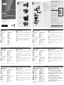
Hardware Review
UEH4102L Front View
1
Power LED
2
Link LED
3
Host LED
4
Activity LED
UEH4102L Rear View
5
Confi g Port*
6
Mode Switch*
7
USB Type-B Port
8
Link Port (RJ-45)
*The Confi g Port / Mode Switch are reserved for engineering service
B
Hardware Installation
1
Prepare two CAT 5e/6/7 patch cables (max. 100m) to the UEH4102L/R’s rear
panel Link port (RJ-45). Connect the other end to a Gigabit Ethernet structure.
2
Connect the included USB 2.0 cable to the UEH4102L’s rear panel USB Type-B
port. Connect the other end to a computer’s USB Type-A port.
3
Use the 4 USB 2.0 ports on UEH4102R to connect additional USB peripheral
devices.
4
Plug an AC Adapter power cord into the Power Jack on the UEH4102R’s back
panel. Plug the other end into an appropriate power source.
5
Check the front panel LEDs to monitor power, link, host, and activity.
A
Hardware Review
B
Hardware Installation
© Copyright 2018 ATEN
®
International Co., Ltd.
ATEN and the ATEN logo are trademarks of ATEN International Co., Ltd. All rights reserved. All
other trademarks are the property of their respective owners.
This product is RoHS compliant.
Part No. PAPE-1223-M50G
Printing Date: 03/2018
4-Port USB 2.0 Cat 5 Extender over LAN
Quick Start Guide
UEH4102
UEH4102R Front View
1
USB Type-A Ports
2
Power LED
3
Link LED
4
Host LED
5
Activity LED
UEH4102R Rear View
6
Power Jack
7
Confi g Port*
8
Mode Switch*
9
Link Port (RJ-45)
Support and Documentation Notice
All information, documentation, fi rmware, software utilities, and
specifi cations contained in this package are subject to change without
prior notifi cation bythe manufacturer.
To reduce the environmental impact of our products, ATEN
documentation and software can be found online at
http://www.aten.com/download/
Technical Support
www.aten.com/support
이 기기는 가정용(B급) 전자파적합기기로서 주로 가정에서 사용하는 것을 목적
으로 하며, 모든 지역에서 사용할 수 있습니다.
EMC Information
FEDERAL COMMUNICATIONS COMMISSION INTERFERENCE
STATEMENT:
This equipment has been tested and found to comply with
the limits for a Class B digital service, pursuant to Part
15 of the FCC rules. These limits are designed to provide
reasonable protection against harmful interference in a
residential installation. Any changes or modifi cations made
to this equipment may void the user s authority to operate
this equipment. This equipment generates, uses, and can
radiate radio frequency energy. If not installed and used in
accordance with the instructions, may cause harmful interference to radio communications. However,
there is no guarantee that interference will not occur in a particular installation. If this equipment does
cause harmful interference to radio or television reception, which can be determined by turning the
equipment off and on, the user is encouraged to try to correct the interference by one or more of the
following measures:
- Reorient or relocate the receiving antenna;
- Increase the separation between the equipment and receiver;
- Connect the equipment into an outlet on a circuit different from
that to which the receiver is connected;
- Consult the dealer/an experienced radio/television technician for help.
FCC Caution: Any changes or modifi cations not expressly approved by the party responsible for
compliance could void the user's authority to operate this equipment.
Suggestion: Shielded twisted pair (STP) cables must be used with the unit to ensure compliance with
FCC & CE standards.
This device complies with Part 15 of the FCC Rules. Operation is subject to the following two
conditions: (1) this device may not cause harmful interference, and (2) this device must accept any
interference received, including interference that may cause undesired operation.
Scan for
more information
UEH4102L Front View
UEH4102R Front View
UEH4102L Rear View
UEH4102R Rear View
4
1
1
2
3
2 4
3 5
7
8
5
6
8
9
6
7
Package Contents
1 UEH4102L 4-Port USB 2.0 Cat 5
Extender over LAN (Local unit)
1 UEH4102R 4-Port USB 2.0 Cat 5
Extender over LAN (Remote unit)
1 Power Adapter
1 USB 2.0 Type-A to Type-B Cable
1 User Instructions
UEH4102 4-портовый USB 2.0 Cat 5 удлинитель по LAN
www.aten.com
Local
Remote
4
1
2
3
max. 100m
max. 100m
A
Aperçu du matériel
Vue avant de l'UEH4102L
1
LED d'alimentation
2
LED Liaison
3
LED Hôte
4
LED d'activité
Vue arrière de l'UEH4102L
5
Port de confi guration*
6
Commutateur de mode*
7
Port USB Type-B
8
Port Liaison (RJ-45)
*Le port de confi guration/commutateur de mode sont réservés au service d'ingénierie
B
Installation du matériel
1
Préparez deux câbles de brassage CAT 5e/6/7 (max. 100 m) vers le port Liaison
(RJ-45) du panneau arrière de l'UEH4102L/R. Raccordez l'autre extrémité à une
structure Gigabit Ethernet.
2
Raccordez le câble USB 2.0 inclus au port USB Type-B du panneau arrière de
l'UEH4102L. Raccordez l'autre extrémité au port USB Type-A d'un ordinateur.
3
Utilisez les 4 ports USB 2.0 de l'UEH4102R pour connecter des périphériques
USB supplémentaires.
4
Branchez le cordon d'alimentation d'un adaptateur secteur CA dans la prise
d'alimentation du panneau arrière de l'UEH4102R. Branchez l'autre extrémité
dans une source d'alimentation appropriée.
5
Vérifi ez les LED du panneau avant pour surveiller l'alimentation, la liaison,
l'hôte et l'activité.
Vue avant de l'UEH4102R
1
Ports USB Type A
2
LED d'alimentation
3
LED Liaison
4
LED Hôte
5
LED d'activité
Vue arrière de l'UEH4102R
6
Fiche d'alimentation
7
Port de confi guration*
8
Commutateur de mode*
9
Port Liaison (RJ-45)
A
Hardwareübersicht
UEH4102L – Ansicht von vorne
1
Betriebsanzeige-LED
2
Verbindung-LED
3
Host-LED
4
Aktivität-LED
UEH4102L – Ansicht von hinten
5
Konfi gurationsport*
6
Modusschalter*
7
USB-Type-B-Port
8
Verbindungsport (RJ-45)
*Konfi gurationsport/Modusschalter für Technikdienst reserviert
B
Hardwareinstallation
1
Bereiten Sie zwei Cat-5e/6/7-Patch-Kabel (max. 100 m) am Verbindungsport
(RJ-45) der Rückblende von UEH4102L/R vor. Verbinden Sie das andere Ende
mit einer Gigabit-Ethernet-Struktur.
2
Verbinden Sie das beigefügte USB-2.0-Kabel mit dem USB-Type-B-Port an der
Rückblende des UEH4102L. Verbinden Sie das andere Ende mit dem USB-Type-
A-Port eines Computers.
3
Schließen Sie über die 4 USB-2.0-Ports am UEH4102R zusätzliche USB-
Peripheriegeräte an.
4
Schließen Sie ein Netzteilkabel am Netzanschluss an der Rückblende des
UEH4102R an. Verbinden Sie das andere Ende mit einer geeigneten Steckdose.
5
Prüfen Sie die LEDs an der Frontblende zur Überwachung von Betriebsstatus,
Verbindung, Host und Aktivität.
UEH4102R – Ansicht von vorne
1
USB-Type-A-Ports
2
Betriebsanzeige-LED
3
Verbindung-LED
4
Host-LED
5
Aktivität-LED
UEH4102R – Ansicht von hinten
6
Netzanschluss
7
Konfi gurationsport*
8
Modusschalter*
9
Verbindungsport (RJ-45)
A
Revisión de hardware
Vista frontal del UEH4102L
1
LED de alimentación
2
LED de enlace
3
LED de anfi trión
4
LED de actividad
Vista posterior del UEH4102L
5
Puerto de confi guración*
6
Conmutador de modo*
7
Puerto USB tipo B
8
Puerto de enlace (RJ-45)
*El puerto de confi guración/Conmutador de modo están reservados para el servicio de
ingeniería
B
Instalación del hardware
1
Prepare dos cables de parche CAT 5e/6/7 (máximo 100m) en el puerto de
enlace del panel posterior del UEH4102L/R (RJ-45). Conecte el otro extremo a
una estructura Gigabit Ethernet.
2
Conecte el cable USB 2.0 incluido al puerto USB tipo B del panel posterior del
UEH4102L. Conecte el otro extremo al puerto USB tipo A de un PC.
3
Use los 4 puertos USB 2.0 del UEH4102R para conectar dispositivos periféricos
USB adicionales.
4
Enchufe un cable de alimentación del adaptador de CA en el conector de
alimentación en el panel posterior del UEH4102R. Conecte el otro extremo a
una fuente de alimentación adecuada.
5
Verifi que los LEDs del panel frontal para monitorizar la alimentación, enlace,
anfi trion y la actividad.
Vista frontal del UEH4102R
1
Puertos USB tipo A
2
LED de alimentación
3
LED de enlace
4
LED de anfi trión
5
LED de actividad
Vista posterior del UEH4102R
6
Conector de alimentación
7
Puerto de confi guración*
8
Cambio de modo*
9
Puerto de enlace (RJ-45)
A
Descrizione hardware
Vista anteriore UEH4102L
1
LED alimentazione
2
LED Link
3
LED host
4
LED attività
Vista posteriore UEH4102L
5
Porta confi g*
6
Interruttore modalità*
7
Porta USB tipo B
8
Porta Link (RJ-45)
*Porta confi g / Interruttore modalità sono riservati per servizio tecnico
B
Installazione dell'hardware
1
Preparare due cavi patch CAT 5e/6/7 (max. 100 m) alla porta Link del pannello
posteriore di UEH4102L/R (RJ-45). Collegare l'altra estremità ad una struttura
Gigabit Ethernet.
2
Collegare il cavo USB 2.0 in dotazione alla porta USB tipo B del pannello
posteriore di UEH4102L. Collegare l'altra estremità ad una porta USB tipo A
del computer.
3
Utilizzare le 4 porte USB 2.0 su UEH4102R per collegare altre periferiche USB.
4
Inserire un cavo di alimentazione dell'adattatore CA nel connettore di
alimentazione del pannello posteriore di UEH4102R. Inserire l'altra estremità
nella fonte di alimentazione adeguata.
5
Controllare i LED del pannello anteriore per monitorare alimentazione, link,
host e attività.
Vista anteriore UEH4102R
1
Porte USB tipo A
2
LED alimentazione
3
LED Link
4
LED host
5
LED attività
Vista posteriore UEH4102R
6
Connettore di alimentazione
7
Porta confi g*
8
Interruttore modalità*
9
Porta Link (RJ-45)
A
Обзор аппаратного обеспечения
UEH4102L Вид спереди
1
Индикатор питания
2
Индикатор связи
3
Индикатор узла
4
Индикатор активности
UEH4102L Вид сзади
5
Порт настройки*
6
Переключатель режимов*
7
Порт USB тип В
8
Порт связи (RJ-45)
*Порт настройки/ Переключатель режимов зарезервированы для технического
обслуживания
B
Установка аппаратного обеспечения
1
Приготовьте два коммутационных кабеля CAT 5e/6/7 (макс. 100 м) для
подключения к порту связи UEH4102L/R на задней панели (RJ-45).
Другой конец кабелей подключите к структуре Gigabit Ethernet.
2
Подключите входящий в комплект кабель USB 2.0 к порту USB типа В
на задней панели UEH4102L. Другой конец кабеля подключите к порту
USB типа А на компьютере.
3
4 порта USB 2.0 на UEH4102R служат для подключения
дополнительных периферийных устройств USB.
4
Подключите шнур адаптера питания переменного тока к разъему
питания на задней панели UEH4102R. Другой конец шнура подключите
к соответствующему источнику питания.
5
Индикаторы на передней панели позволяют следить за состоянием
питания, связи, узла и активности.
UEH4102R Вид спереди
1
Порты USB тип А
2
Индикатор питания
3
Индикатор связи
4
Индикатор узла
5
Индикатор активности
UEH4102R Вид сзади
6
Разъём питания
7
Порт настройки*
8
Переключатель режимов*
9
Порт связи (RJ-45)
La pagina si sta caricando...
-
 1
1
-
 2
2


in altre lingue
- English: ATEN UEH4102 Quick start guide
- français: ATEN UEH4102 Guide de démarrage rapide
- español: ATEN UEH4102 Guía de inicio rápido
- Deutsch: ATEN UEH4102 Schnellstartanleitung
- русский: ATEN UEH4102 Инструкция по началу работы
- português: ATEN UEH4102 Guia rápido
- polski: ATEN UEH4102 Skrócona instrukcja obsługi
- 日本語: ATEN UEH4102 クイックスタートガイド
- Türkçe: ATEN UEH4102 Hızlı başlangıç Kılavuzu