
VK248 8-Channel Relay Expansion Box
VM0808HA 8 x 8 4K HDMI Matrix Switch Quick Start Guide
A
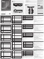
Overview
No. Components Description
1
Relay LEDs
The eight LEDs light Green to indicate signals are being
transmitted (closed loop) between a device and VK2100,
for each port.
2
DC Output
Overload
LED
The LED lights orange to indicate the DC output exceeds
the maximum output allowable.
When the LED lights orange, disconnect any of the
connected devices to keep the total output under 3.6 W,
and then press and hold the reset button for at least 8
seconds, until all Relay LEDs light (on/off) once in unison
to indicate the device is shutting down. After 5 seconds,
all Relay LEDs will light solid Green while the device is
booting up, and then turn off when the reset is complete.
3
LAN LED
The LED blinks green to indicate the VK248 has connected
to the network.
4
VK Link LED
The LED lights green when the VK248 establishes a
connection to the VK2100. To establish a connection, the
VK248 must be connected to the network and confi gured
in the VK6000 software.
A
Vue d'ensemble
No. Components Description
1
LED des relais
Les huit LED s’illuminent en vert pour indiquer que des
signaux sont en cours de transmission (boucle fermée) entre
un périphérique et le VK2100, pour chaque port.
2
LED de
surcharge de
la sortie CC
La LED s’illumine en orange pour indiquer que la sortie CC
dépasse le maximum admissible en sortie.
Lorsque la LED s’allume en orange, débranchez l’un des
périphériques connectés pour maintenir la puissance
totale en dessous de 3,6 W, puis appuyez sur le bouton de
réinitialisation et maintenez-le enfoncé pendant au moins
8 secondes, jusqu’à ce que toutes les LED Relais s’allument
(Allumé/Éteint) une fois à l’unisson pour indiquer que le
périphérique est en cours d’arrêt. Au bout de 5 secondes,
toutes les Relais sont allumées en vert pendant que
l’appareil est en cours de démarrage, puis elles s’éteignent
lorsque la réinitialisation est terminée.
3
LED LAN
La LED clignote en vert pour indiquer que le VK248 s'est
connecté avec succès au réseau.
4
LED Liaison VK
La LED s’illumine en vert lorsque le VK248 établit une
connexion avec le VK2100. Pour établir une connexion, le
VK248 doit être connecté au réseau et confi guré dans le
logiciel VK6000.
A
Descrizione
Nr. Componenti Descrizione
1
LED relè
Los ocho LEDs se iluminan en verde para indicar que se
transmiten señales (bucle cerrado) entre un dispositivo y el
VK2100 para cada puerto.
2
LED
sovraccarico
uscita DC
El LED se ilumina de color naranja para indicar que la
salida de CC excede la salida máxima permitida.
Cuando el LED se ilumina en naranja, desconecte
cualquiera de los dispositivos conectados para mantener la
salida total inferior a 3,6 W, y a continuación, mantenga
presionado el botón de reinicio durante al menos 8
segundos hasta que se encienden y apagan todas las luces
LED de retransmisión conjuntamente para indicar que el
dispositivo se está apagando. Tras 5 segundos, todos los
LEDs de retransmisión se iluminarán en verde fi jo mientras
el dispositivo arranca, y a continuación, se apagarán una
vez que se haya fi nalizado el reinicio.
3
LED LAN
Il LED lampeggia di colore verde per indicare che il VK248
si è collegato alla rete.
4
LED VK Link
Il LED si accende di colore verde quando il VK248
stabilisce una connessione con VK2100. Per stabilire una
connessione, il VK248 deve essere collegato alla rete e
confi gurato nel software VK6000.
5
USB LED
and Port
This is where a USB drive plugs in to upgrade the
fi rmware.
The USB LED blinks green to indicate the fi rmware is being
installed, and lights solid green to indicate a successful
installation. The LED lights orange to indicate the fi rmware
upgrade failed.
6
Reset
Pushbutton
This semi-recessed pushbutton can be pressed to reset the
network settings. The LAN LED will turn off and then light
Green when the network connection is reestablished.
If the reset pushbutton is pressed for 8 seconds it will
reboot the VK248, and all Relay LEDs will light (on/off)
once in unison to indicate the device is shutting down.
After 5 seconds, all Relay LEDs will light solid Green while
the device is booting up, and then turn off when the reset
is complete.
7
Power LED
The LED lights green when power is being supplied by the
power adapter or the LAN port via Power over Ethernet
(PoE).
8
Controller
ID
Set this 16-segment switch to the same controller ID of
the VK2100 that it connects to over the network.
9
Expander ID
Set this 8-segment switch to a unique ID for the unit and
use it to confi gure the VK248 in the VK6000 software.
5
LED et port
USB
Il s'agit de l'endroit où une clé USB se branche pour mettre
à niveau le fi rmware.
La LED USB clignote en vert pour indiquer que le fi rmware
est en cours d'installation, et s’illumine en vert pour
indiquer une installation réussie. La LED s'illumine en
orange pour indiquer que la mise à niveau du fi rmware a
échoué.
6
Bouton
poussoir de
réinitialisation
Ce bouton poussoir semi-encastré peut être actionné pour
réinitialiser les paramètres réseau. La LED LAN s’éteint puis
s’illumine en vert lorsque la connexion réseau est rétablie.
Si le bouton-poussoir de réinitialisation est enfoncé
pendant 8 secondes, cela redémarre le VK248, et toutes
les LED Relais s’allument (Allumé/Éteint) une fois à l’unisson
pour indiquer que l’appareil est en cours d’arrêt. Au bout
de 5 secondes, toutes les Relais sont allumées en vert
pendant que l’appareil est en cours de démarrage, puis
elles s’éteignent lorsque la réinitialisation est terminée.
7
DEL
d'alimentation
La LED s'illumine en vert lorsque l'alimentation est fournie
par l'adaptateur secteur ou par le port LAN via Power over
Ethernet (PoE).
8
ID contrôleur
Réglez ce commutateur à 16 segments sur le même ID
contrôleur du VK2100 auquel il se connecte sur le réseau.
9
ID extenseur
Réglez ce commutateur à 8 segments sur un ID unique
pour l'unité et utilisez-le pour confi gurer le VK248 dans le
logiciel VK6000.
5
LED e porta
USB
Porta alla quale si collega una chiavetta USB per
aggiornare il fi rmware.
Il LED USB lampeggia di colore verde per indicare che
è in corso l’installazione del fi rmware, e resta acceso
di colore verde per indicare la corretta installazione.
Il LED si accende di colore arancione per indicare che
l'aggiornamento del fi rmware non è riuscito.
6
Tasto Reset
Este pulsador semiempotrado puede ser presionado para
restablecer la confi guración de red. El LED LAN se apagará
y luego se iluminará en verde cuando la conexión de red
se haya reestablecido.
Si se presiona el botón de reinicio durante 8 segundos,
se reiniciará el VK248 y todos los LEDs de retransmisión
se encenderán y se apagarán una vez conjuntamente
para indicar que el dispositivo se está apagando. Tras 5
segundos, todos los LEDs de retransmisión se iluminarán
en verde fi jo mientras el dispositivo arranca, y a
continuación, se apagarán una vez que se haya fi nalizado
el reinicio.
7
LED
alimentazione
Il LED si accende di colore verde quando l'alimentazione è
fornita tramite l'adattatore di corrente o la porta LAN via
PoE (Power over Ethernet).
8
ID controller
Impostare questo switch a 16 segmenti sullo stesso
Controller ID del VK2100 che si connette alla rete.
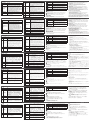
10
Grounding
Terminal
This is where the grounding wire attaches. Always ground
the unit with a proper grounding wire and suitable
grounded object.
11
Power Jack
This standard power jack is where the power adapter
plugs in.
12
LAN (PoE)
Port
This RJ-45 port is used for the network connection and
powers the unit via Power over Ethernet (PoE) when the
power adapter is unplugged.
13
DC Output
Ports
This DC output connector provides a total power output
of 12 VDC / 300 mA max.
14
Relay
Channels
Eight channels; normally open, isolated relays with a
contact rating of 24 VDC, 2A max.
B
Installation
Mounting
To rack mount the VK248:
1
Use the (4) screws supplied with the mounting kit to attach the brackets to
the sides of the unit.
2
Screw the brackets to the rack, with the front or rear of the unit facing out,
as shown in diagram B-2.
Setup
Hardware
1. Connect the hardware devices to the Relay and DC Output ports.
10
Borne de terre
Il s'agit de l'endroit où le câble de terre est fi xé. Reliez
toujours l'unité à la terre avec un fi l de mise à la terre et un
objet correctement mis à la terre.
11
Fiche
d'alimentation
Cette prise d'alimentation standard est l'endroit où
l'adaptateur secteur se branche.
12
Port LAN (PoE)
Ce port RJ-45 est utilisé pour la connexion réseau et
alimente l'unité via Power over Ethernet (PoE) lorsque
l'adaptateur d'alimentation est débranché.
13
Ports de sortie
CC
Ce connecteur de sortie CC fournit une puissance totale
de 12 VCC / 300 mA maxi.
14
Voies relais
Huit voies; relais isolés ouverts au repos avec un contact
nominal de 24 VCC, 2A maxi.
B
Installation
Montage
Pour monter le VK248 en rack :
1
Utilisez les (4) vis fournies avec le kit de montage pour fi xer les supports sur
les côtés de l’unité.
2
Vissez les supports au rack, avec l'avant ou l'arrière de l'appareil dirigé vers
l'extérieur, comme indiqué sur le schéma B-2.
Confi guration
Matériel
1.
Connectez les périphériques matériels au relais et aux ports de sortie CC.
9
ID modulo di
espansione
Impostare questo interruttore a 8 segmenti su un ID
univoco per l’unità ed utilizzarlo per confi gurare il VK248
sul software VK6000.
10
Terminale di
massa
Qui va collegato il cavo di messa a terra. L’unità deve
sempre essere dotata di messa a terra con cavo appropriato
per la messa a terra collegato ad un dispersore di terra
appropriato.
11
Connettore
d'alimentazione
Questo connettore standard di alimentazione serve per
collegare l’adattatore di corrente.
12
Porta LAN
(PoE)
Questa porta RJ-45 è utilizzato per la connessione di
rete ed alimentare l'unità via PoE (Power over Ethernet)
quando l'alimentatore non è collegato.
13
Porte di uscita
DC
Questo connettore di uscita DC fornisce una potenza
complessiva di uscita 12 VDC / 300 mA al massimo.
14
Canali relè
Otto canali; normalmente aperti, relè isolati con una
tensione nominale di contatto di 24 V DC, 2A al massimo.
B
Installazione
Installazione
Installazione su rack di VK248:
1
Utilizzare le (4) viti fornite con il kit di installazione per fi ssare le staffe sui
lati dell’unità.
2
Fissare le staffe al rack, con la parte anteriore o posteriore dell'unità rivolta
verso l'esterno, come mostrato nell’illustrazione B-2.
2. Use an Ethernet cable to connect the unit’s LAN port to the network.
3. (Optional) Plug the power adapter into the unit's power jack and to an AC
power source.
Switches
4. Set the Controller ID to the same ID as the VK2100.
5. Set the Expander ID to a unique ID for this unit.
Confi guration
6. Add the VK248 in the VK6000 software and confi gure the hardware devices
connected to it.
7. Upload the viewer profi le to the controller. The VK Link LED lights green
when the VK248 is successfully connected to the VK2100.
Refer to the ATEN Control System User Manual for more details about
confi guring the VK248.
Firmware Upgrades
1. Download the fi rmware upgrade fi le: http://www.aten.com/download/
2. Enter the VK248’s default IP address (192.168.0.60) into a web browser to
access the GUI.
3. Enter password and click Login.
4. Click Update Firmware, browse to select the FW upgrade fi le and click
Update.
The fi rmware can also be installed by copying the upgrade fi le to a folder
named "VK248" on a USB drive and plugging it into the USB port.
2.
Utilisez un câble Ethernet pour raccorder le port LAN de l'unité au réseau.
3. (Optionnel) Raccordez l'adaptateur d'alimentation à la prise d'alimentation
de l'unité et à une source d'alimentation CA.
Commutateurs
4. Réglez l'ID du contrôleur sur le même ID que le VK2100.
5. Réglez l'ID de l’extenseur sur un ID unique pour cet unité.
Confi guration
6. Ajoutez le VK248 dans le logiciel VK6000 et confi gurez les périphériques
matériels qui y sont connectés.
7. Téléchargez le profi l di visualiseur vers le contrôleur. La LED Liaison VK s'illumine
en vert lorsque le VK248 établit avec succès une connexion avec le VK2100.
Consultez le manuel d'utilisation du système de contrôle ATEN pour plus de
détails sur la confi guration du VK248.
Mises à niveau du fi rmware
1. Téléchargez le fi chier de mise à niveau du fi rmware :
http://www.aten.com/download/
2. Entrez l'adresse IP (192.168.0.60) du VK248 dans un navigateur Web pour
accéder à l'interface graphique.
3. Saisissez le password et cliquez sur Connexion.
4. Cliquez sur Mettre à jour le fi rmware et sur Parcourir pour sélectionner le
fi chier de mise à niveau FW, puis cliquez sur Mettre à jour.
Vous pouvez également installer le fi rmware en copiant le fi chier de mise à
niveau dans un dossier nommé « VK248 » sur une clé USB et en la branchant
sur le port USB.
B
Package Contents
1 VK248 8-Channel Relay Expansion Box
1 Mounting Kit
9 Terminal Blocks
1 User Instructions
Front View
Mounting
Rear View
Installation
© Copyright 2018 ATEN
®
International Co., Ltd.
ATEN and the ATEN logo are trademarks of ATEN International Co., Ltd. All rights reserved. All
other trademarks are the property of their respective owners.
This product is RoHS compliant.
Part No. PAPE-1223-F71G Printing Date: 01/2018
8-Channel Relay Expansion Box
Quick Start Guide
VK248
ATEN VanCryst
™
Boîtier d’extension relais VK248 8 voies
www.aten.com
8-Kanal-Relais-Erweiterungsbox VK248
www.aten.com
Modulo di espansione relè 8 canali VK248
www.aten.com
Caja de expansión de retransmisión de 8 canales VK248
www.aten.com
1
2
or
1
3
4 5
6
7
2
14
10
11
8
9
12 13
Support and Documentation Notice
All information, documentation, fi rmware,
software utilities, and specifi cations
contained in this package are subject to
change without prior notifi cation by
the manufacturer.
To reduce the environmental impact of our
products, ATEN documentation and software
can be found online at
http://www.aten.com/download/
Technical Support
www.aten.com/support
이 기기는 업무용(A급) 전자파적합기기로서 판매자 또는
사용자는 이 점을 주의하시기 바라며, 가정외의 지역에
서 사용하는 것을 목적으로 합니다.
EMC Information
FEDERAL COMMUNICATIONS COMMISSION INTERFERENCE STATEMENT:
This equipment has been tested and found to comply with the limits
for a Class A digital device, pursuant to Part 15 of the FCC Rules.
These limits are designed to provide reasonable protection against
harmful interference when the equipment is operated in a commercial
environment. This equipment generates, uses, and can radiate radio
frequency energy and, if not installed and used in accordance with
the instruction manual, may cause harmful interference to radio
communications. Operation of this equipment in a residential area
is likely to cause harmful interference in which case the user will be
required to correct the interference at his own expense.
FCC Caution: Any changes or modifi cations not expressly approved by
the party responsible for compliance could void the user's authority to
operate this equipment.
Warning: Operation of this equipment in a residential environment
could cause radio interference.
This device complies with Part 15 of the FCC Rules. Operation is subject
to the following two conditions:(1) this device mat not cause harmful
interference, and(2) this device must accept any interference received,
including interference that may cause undesired operation.
A
Übersicht
Nr.
Komponenten Beschreibung
1
Relais-LEDs
Die acht LEDs zeigen für jeden Port durch grünes Leuchten
an, dass Signale zwischen einem Gerät und der VK2100
übertragen werden (geschlossener Loop).
2
Gleichspannungs
ausgabe-
Überlastung-LED
Die LED zeigt durch orangefarbenes Leuchten an, dass die
Gleichspannungsausgabe die maximal erlaubte Ausgabe
übersteigt.
Trennen Sie alle angeschlossenen Geräten, wenn die LED
orange leuchtet, damit die Gesamtausgabe unter 3,6
W liegt. Halten Sie dann die Reset-Taste mindestens 8
Sekunden gedrückt, bis alle Relais-LEDs zur Anzeige der
Geräteabschaltung gleichzeitig einmal aufl euchten (ein/aus).
Nach 5 Sekunden leuchten alle Relais-LEDs grün, während das
Gerät hochfährt; bei Abschluss des Neustarts erlöschen sie.
3
LAN-LED
Die LED zeigt durch grünes Blinken an, dass die VK248 mit
dem Netzwerk verbunden wurde.
4
VK LINK-LED
Die LED leuchtet grün, wenn die VK248 eine Verbindung zum
VK2100 herstellt. Zum Herstellen einer Verbindung muss die
VK248 mit dem Netzwerk verbunden und in der VK6000-
Software konfi guriert werden.
5
USB-LED und
-Port
Hier schließen Sie ein USB-Laufwerk zur Firmware-
Aktualisierung an.
Die USB-LED zeigt durch grünes Blinken an, dass die Firmware
installiert wird; sie leuchtet grün, sobald die Installation
erfolgreich abgeschlossen wurde. Durch orangefarbenes
Leuchten zeigt die LED an, dass die Firmware-Aktualisierung
fehlgeschlagen ist.
6
Reset-Taste
Diese partiell vertiefte Taste kann zum Rücksetzen der
Netzwerkeinstellungen gedrückt werden. Die LAN-LED erlischt
und leuchtet dann grün, wenn die Netzwerkverbindung
wiederhergestellt ist.
Wenn die Reset-Taste 8 Sekunden gedrückt wird, startet die
VK248 neu und alle Relais-LEDs leuchten zur Anzeige der
Geräteabschaltung gleichzeitig einmal auf (ein/aus). Nach 5
Sekunden leuchten alle Relais-LEDs grün, während das Gerät
hochfährt; bei Abschluss des Neustarts erlöschen sie.
7
Betrieb-LED
Die LED leuchtet grün, wenn das Gerät per Netzteil oder den
LAN-Port über Power over Ethernet (PoE) mit Strom versorgt wird.
8
Controller-ID
Stellen Sie diesen 16-stufi gen Schalter auf die gleiche
Controller-ID des VK2100 ein, mit dem das Produkt über das
Netzwerk verbunden ist.
9
Expander-ID
Stellen Sie diesen 8-stufi gen Schalter auf eine eindeutige ID
für das Gerät ein und nutzen Sie ihn zur Konfi guration der
VK248 in der VK6000-Software.
10
Erdungsklemme
Hier schließen Sie das Erdungskabel an. Erden Sie das Gerät
immer mit einem geeigneten Erdungskabel und einem
angemessen geerdeten Objekt.
11
Netzanschluss
An diesem standardmäßigen Netzanschluss schließen Sie das
Netzteil an.
12
LAN-Port (PoE)
Dieser RJ-45-Port dient der Netzwerkverbindung und versorgt
das Gerät per Power over Ethernet (PoE) mit Strom, wenn das
Netzteil angeschlossen ist.
13
Gleichspannungs
ausgänge
Dieser Gleichspannungsausgang liefert eine Gesamtstromausgabe
von 12 V Gleichspannung / 300 mA Max.
14
Relais-Kanäle.
Acht Kanäle; normalerweise offen, isolierte Relais mit einer
Kontaktbewertung von 24 V Gleichspannung, 2 A Max.
B
Installation
Montage
So montieren Sie die VK248 im Rack:
1
Bringen Sie die Halterungen mit den im Montageset enthaltenen Schrauben (4)
an den Seiten des Gerätes an.
2
Schrauben Sie die Halterungen an das Rack, wobei Vorder- und Rückseite des
Gerätes wie in Abbildung B-2 gezeigt nach außen zeigen.
Einrichtung
Hardware
1. Verbinden Sie die Hardwaregeräte mit den Relais- und Gleichspannungsausgängen.
2. Verbinden Sie den LAN-Port des Gerätes über ein Ethernet-Kabel mit dem
Netzwerk.
3. (Optional) Schließen Sie das Netzteil an den Netzanschluss des Gerätes und
an eine Stromversorgung mit Wechselspannung an.
Schalter
4. Stellen Sie die Controller-ID auf die ID des VK2100 ein.
5. Stellen Sie die Expander-ID auf eine eindeutige ID für dieses Gerät ein.
Konfi guration
6. Fügen Sie die VK248 in der VK6000-Software hinzu und konfi gurieren Sie
die daran angeschlossenen Hardwaregeräte.
7.
Laden Sie das Betrachterprofi l auf den Controller hoch. Die VK LINK-LED
leuchtet grün, wenn die VK248 eine Verbindung zum VK2100 hergestellt hat.
Weitere Einzelheiten über die Konfi guration der VK248 entnehmen Sie bitte
der Bedienungsanleitung des ATEN-Kontrollsystems.
Firmware-Aktualisierungen
1. Firmware-Aktualisierungsdatei herunterladen:
http://www.aten.com/download/
2. Geben Sie zum Zugreifen auf die Benutzeroberfl äche die Standard-IP-
Adresse (192.168.0.60) der VK248 in einen Webbrowser ein.
3. Geben Sie das password und klicken Sie auf Anmelden.
4. Klicken Sie auf Firmware aktualisieren und dann zur Auswahl der FW-
Aktualisierungsdatei auf Durchsuchen; klicken Sie anschließend auf
Aktualisieren.
Alternativ können Sie die Firmware installieren, indem Sie die
Aktualisierungsdatei auf ein USB-Laufwerk in einen Ordner namens „VK248“
kopieren und dieses an den USB-Port anschließen.
A
Información general
Nº Componentes Descripción
1
LEDs de
retransmisión
Gli otto LED si accendono di colore verde per indicare
che i segnali sono trasmessi (loop chiuso) tra un
dispositivo e VK2100, per ciascuna porta.
2
LED de
sobrecarga de
salida de CC
Il LED si accende di colore arancione per indicare che
l’uscita DC supera il massimo consentito di uscita.
Quando il LED si accende di colore arancione, scollegare
tutti i dispositivi collegati per tenere l’uscita totale sotto
i 3,6 W, quindi tenere premuto per almeno 8 secondi
il tasto Reset fi nché tutti i LED Relay si accendono
e spengo una volta all’unisono per indicare che il
dispositivo si sta spegnendo. Dopo 5 secondi, tutti i
LED Relay si accenderanno di colore verde mentre il
dispositivo si avvia, quindi si spegneranno quando il
ripristino è completato.
3
LED DE LAN
El LED parpadea en verde para indicar que el VK248 se
ha conectado a la red.
4
LED de vínculo
VK
El LED se ilumina en verde cuando el VK248 establece
una conexión con el VK2100. Para establecer una
conexión, el VK248 debe estar conectado a la red y
confi gurado en el software VK6000.
5
LED y puerto
USB
Aquí es donde se conecta una unidad USB para
actualizar el fi rmware.
El LED del USB parpadea en verde para indicar que el
fi rmware se está instalando, y se ilumina en verde fi jo
para indicar una instalación exitosa. El LED se ilumina
de color naranja para indicar que la actualización del
fi rmware ha fallado.
6
Pulsador para
restablecer
Questo tasto a semi-incasso può essere premuto per
ripristinare le impostazioni di rete. Il LED LAN si spegnerà
e poi si accenderà di colore verde quando la connessione
di rete è ristabilita.
Se il tasto Reset è premuto per 8 secondi, il VK248
si riavvierà e tutti i LED IR/seriale si accenderanno e
spegneranno all’unisono per indicare che il dispositivo
si sta spegnendo. Dopo 5 secondi, tutti i LED Relay
si accenderanno di colore verde mentre il dispositivo
si avvia, quindi si spegneranno quando il ripristino è
completato.
7
LED de
alimentación
El LED se ilumina de color verde cuando está siendo
alimentado por el adaptador de alimentación o
alimentación del puerto LAN a través de Ethernet (PoE).
8
Identifi cador de
controlador
Ajuste este conmutador de 16 segmentos al mismo ID
del controlador del VK2100 que se conecta a través de
la red.
9
ID de expansor
Ajuste este conmutador de 8 segmentos a un ID único
de la unidad y utilícelo para confi gurar el VK248 en el
software VK6000.
10
Terminal de
toma de tierra
Aquí es donde se conecta el cable a tierra. Conecte
siempre la unidad a tierra con un cable de conexión a
tierra y a un objeto conectado a tierra adecuadamente.
11
Conector de
alimentación
Este conector de alimentación estándar es donde se
conecta el adaptador de alimentación.
12
Puerto LAN
(PoE)
Este puerto RJ45 se utiliza para la conexión de red y
alimenta la unidad a través de Power over Ethernet (PoE)
cuando el adaptador de corriente está desconectado.
13
Puertos de
salida CC
Este conector de salida de CC proporciona una potencia
total de salida de 12 V CC / 300 mA máx.
14
Canales de
retransmisión
Ocho canales; normalmente abiertos, retransmisiones
aisladas con una califi cación de contactos de 24V CC,
2A máx.
B
Instalación
Montaje
Para el montaje en bastidor del VK248:
1
Utilice los (4) tornillos suministrados con el juego de montaje para fi jar los
soportes a los laterales de la unidad.
2
Atornille los soportes al bastidor, con la parte delantera o posterior de la
unidad hacia afuera, como se muestra en el diagrama B-2.
Confi guración
Hardware
1. Conecte los dispositivos de hardware a los puertos de salida de retransmisión
y de CC.
2.
Utilice un cable Ethernet para conectar el puerto LAN de la unidad a la red.
3. (Opzionale) Enchufe el adaptador de alimentación en el conector de
alimentación de la unidad y a su vez a una fuente de alimentación de CA.
Interruptores
4. Ajuste el ID del controlador al mismo ID que el VK2100.
5. Ajuste el ID del expansor a un ID único para esta unidad.
Confi guración
6. Añada el VK248 en el software VK6000 y confi gure los dispositivos de
hardware conectados a él.
7. Suba el perfi l de visor al controlador. El LED de vínculo VK se ilumina en
verde cuando el VK248 establece una conexión con éxito con el VK2100.
Consulte el Manual del usuario del sistema de control de ATEN para más
detalles sobre la confi guración del VK248.
Actualizaciónes de fi rmware
1. Descargue el archivo de actualización del fi rmware:
http://www.aten.com/download/
2. Inserire l'indirizzo IP predefi nito (192.168.0.60) di VK248 in un browser web
per accedere all’interfaccia utente.
3. Introduzca la password y haga clic en Iniciar sesión.
4. Haga clic en Actualizar fi rmware, Explorar para seleccionar el archivo de
actualización de FW, y a continuación, haga clic en Actualizar.
El fi rmware también se puede instalar copiando el archivo de actualización a una
carpeta llamada "VK248" en una unidad USB y conectarla a un puerto USB.
Scan for
more information
Impostazione
Hardware
1. Collegare i dispositivi hardware alle porte RELAY e DC OUTPUT.
2. Utilizzare un cavo Ethernet per collegare la porta LAN dell'unità alla rete.
3. (Opcional) Collegare l'adattatore di corrente al connettore d'alimentazione
dell’unità e ad una presa di corrente AC.
Interruttori
4. Impostare il Controller ID sullo stesso ID di VK2100.
5. Impostare l’Expander ID su un ID univoco per questa unità.
Confi gurazione
6. Aggiungere il VK248 nel software VK6000 e confi gurare i dispositivi
hardware ad esso collegati.
7. Carica il profi lo visualizzatore sul controller. Il LED VK Link si accende di
colore verde quando il VK248 è collegato correttamente a VK2100.
Fare riferimento al Manuale d'uso del sistema di controllo ATEN per altri
dettagli sulla confi gurazione del VK248.
Aggiornamenti del fi rmware
1. Scaricare il fi le di aggiornamento del fi rmware:
http://www.aten.com/download/
2. Introduzca la dirección IP por defecto del VK248 (192.168.0.60) en un
navegador web para acceder a la interfaz gráfi ca de usuario.
3. Inserire la password e fare clic su Accedi.
4. Fare clic su Aggiorna fi rmware e su Sfoglia per selezionare il fi le di
aggiornamento fi rmware, quindi fare clic su Aggiorna.
In alternativa, è possibile installare il fi rmware copiando il fi le di
aggiornamento fi rmware su una chiavetta USB, in una cartella denominata
"VK248", e quindi collegando la chiavetta alla porta USB.
www.aten.com
A
Overview
La pagina sta caricando ...
-
 1
1
-
 2
2


in altre lingue
- English: ATEN VK248 Quick start guide
- français: ATEN VK248 Guide de démarrage rapide
- español: ATEN VK248 Guía de inicio rápido
- Deutsch: ATEN VK248 Schnellstartanleitung
- русский: ATEN VK248 Инструкция по началу работы
- português: ATEN VK248 Guia rápido
- 日本語: ATEN VK248 クイックスタートガイド