Yamaha DSP-A2070 Manuale del proprietario
- Categoria
- Ricevitori AV
- Tipo
- Manuale del proprietario

DSP
-
A2070
DIGITAL SOUND FIELD
PROCESSING AMPLIFIER
OPERATION MANUAL
CONTENTS
SAFETY INSTRUCTIONS..................................................Inside Front cover
SETUP & ADJUSTMENT..............................................................................3
1-1.GETTING STARTED...............................................................................3
1-2.SETUP....................................................................................................10
1-3.CONTROLS & ADJUSTMENTS...........................................................19
1-4.ADJUSTMENT.......................................................................................23
GENERAL OPERATION .............................................................................29
2-1.PLAYING A SOURCE ...........................................................................29
2-2.RECORDING A SOURCE TO AUDIO/VIDEO TAPE..........................30
(OR DUBBING FROM A TAPE TO ANOTHER)
2-3.DIGITAL SOUND FIELD PROGRAMS.................................................31
2-4.SELECTING SOUND FIELD PROGRAMS..........................................31
2-5.MUTING THE EFFECT SOUND...........................................................32
2-6.SUPERIMPOSED VIDEO PROGRAM/PARAMETER
DISPLAY................................................................................................32
2-7.DESCRIPTIONS OF THE SOUND FIELD PROGRAMS.....................33
2-8.REMOTE CONTROL “LEARNING” FUNCTION..................................39
CREATING YOUR OWN SOUND FIELDS.................................................41
3-1.SELECTING AND EDITING PROGRAM PARAMETERS...................41
3-2.DESCRIPTIONS OF THE DIGITAL SOUND FIELD
PARAMETERS......................................................................................43
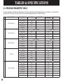
TABLES & SPECIFICATIONS....................................................................48
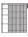
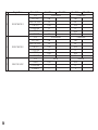
4-1.PROGRAM PARAMETER TABLE........................................................48
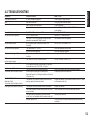
4-2.TROUBLESHOOTING ..........................................................................51
4-3.SPECIFICATIONS.................................................................................52

1 Read Instructions – All the safety
and operating instructions should be
read before the unit is operated.
2 Retain Instructions – The safety and
operating instructions should be retained
for future reference.
3 Heed Warnings – All warnings on the
unit and in the operating instructions
should be adhered to.
4 Follow Instructions – All operating
and other instructions should be
followed.
5 Water and Moisture – The unit
should not be used near water – for
example, near a bathtub, washbowl,
kitchen sink, laundry tub, in a wet
basement, or near a swimming pool, etc.
6 Carts and Stands – The unit should
be used only with a cart or stand that is
recommended by the manufacturer.
6A A unit and cart
combination should be
moved with care. Quick
stops, excessive force,
and uneven surfaces may
cause the unit and cart
combination to overturn.
7 Wall or Ceiling Mounting – The unit
should be mounted to a wall or ceiling
only as recommended by the
manufacturer.
8 Ventilation – The unit should be
situated so that its location or position
does not interfere with its proper
ventilation. For example, the unit should
not be situated on a bed, sofa, rug, or
similar surface, that may block the
ventilation openings; or placed in a built-
in installation, such as a bookcase or
cabinet that may impede the flow of air
through the ventilation openings.
9 Heat – The unit should be situated
away from heat sources such as
radiators, stoves, or other appliances
that produce heat.
10 Power Sources – The unit should be
connected to a power supply only of the
type described in the operating
instructions or as marked on the unit.
11 Power-Cord Protection – Power-
supply cords should be routed so that
they are not likely to be walked on or
pinched by items placed upon or against
them, paying particular attention to cords
at plugs, convenience receptacles, and
the point where they exit from the unit.
12 Cleaning – The unit should be
cleaned only as recommended by the
manufacturer.
13 Nonuse Periods – The power cord of
the unit should be unplugged from the
outlet when left unused for a long period
of time.
14 Object and Liquid Entry – Care
should be taken so that objects do not
fall into and liquids are not spilled into
the inside of the unit.
15 Damage Requiring Service – The
unit should be serviced by qualified
service personnel when:
A. The power-supply cord or the plug
has been damaged;
or
B. Objects have fallen, or liquid has
been spilled into the unit; or
C. The unit has been exposed to rain;
or
D. The unit does not appear to operate
normally or exhibits a marked change in
performance;
or
E. The unit has been dropped, or the
cabinet damaged.
16 Servicing – The user should not
attempt to service the unit beyond those
means described in the operating
instructions. All other servicing should
be referred to qualified service
personnel.
17 Power Lines – An outdoor antenna
should be located away from power
lines.
18 Grounding or Polarization –
Precautions should be taken so that the
grounding or polarization is not defeated.
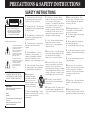
SAFETY INSTRUCTIONS
RISK OF ELECTRIC SHOCK
DO NOT OPEN
CAUTION: TO REDUCE THE RISK OF
ELECTRIC SHOCK, DO NOT REMOVE
COVER (OR BACK), NO USER-SERVICEABLE
PARTS INSIDE, REFER SERVICING TO
QUALIFIED SERVICE PERSONNEL.
The lightning flash with arrowhead
symbol, within an equilateral triangle,
is intended to alert you to the
presence of uninsulated “dangerous
voltage” within the product’s
enclosure that may be of sufficient
magnitude to constitute a risk of
electric shock to persons.
The exclamation point within an
equilateral triangle is intended to alert
you to the presence of important
operating and maintenance
(servicing) instructions in the
literature accompanying the
appliance.
•
Explanation of Graphical Symbols
CAUTION
IMPORTANT!
Please record the serial number of this
unit in the space below.
Model:
Serial No.:
The serial number is located on the rear
of the unit.
Retain this Owner’s Manual in a safe
place for future reference.
WARNING
TO REDUCE THE RISK OF FIRE OR
ELECTRIC SHOCK, DO NOT EXPOSE
THIS UNIT TO RAIN OR MOISTURE.
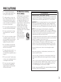
PRECAUTIONS & SAFETY INSTRUCTIONS

1 To ensure the finest performance,
please read this manual carefully. Keep it
in a safe place for future reference.
2 Install your unit in a cool, dry, clean
place – away from windows, heat sources,
and too much vibration, dust, moisture or
cold. Avoid sources of hum (transformers,
motors). To prevent fire or electrical shock,
do not expose to rain and water.
3 Do not operate the unit upside-down. It
may overheat, possibly causing damage.
4 Never open the cabinet. If a foreign
object drops into the set, contact your
dealer.
5 Do not use force on switches, knobs or
cords. When moving the set, first turn the
unit off. Then gently disconnect the power
plug and the cords connecting to other
equipment. Never pull the cord itself.
6 Do not attempt to clean the unit with
chemical solvents; this might damage the
finish. Use a clean, dry cloth.
7 Always set the volume control to “–
∞
”
while lowering the tonearm to play a
record; turn the volume up with the stylus in
the groove.
8 Be sure to read the “Troubleshooting”
section on common operating errors before
concluding that your unit is faulty.
9 Do not connect audio equipment to
the AC outlets on the rear panel if that
equipment requires more power than the
outlets are rated to provide.
We Want You Listening
For A Lifetime
YAMAHA and the Electronic Industries
Association’s Consumer Electronics
Group want you to get the most out of
your equipment by playing it at a safe
level. One that lets the sound come
through loud and clear without annoying
blaring or distortion – and, most
importantly, without affecting your
sensitive hearing. Since hearing
damage from loud sounds is often
undetectable until it is too late, YAMAHA
and the Electronic
Industries Association’s
Consumer Electronics
Group recommend you to
avoid prolonged exposure
from excessive volume
levels.
PRECAUTIONS
FCC INFORMATION
1. IMPORTANT NOTICE : DO NOT MODIFY THIS UNIT!
This product, when installed as indicated in the instructions contained in this
manual, meets FCC requirements. Modifications not expressly approved by
Yamaha may void your authority, granted by the FCC, to use the product.
2. IMPORTANT : When connecting this product to accessories and/or another
product use only high quality shielded cables. Cable/s supplied with this
product MUST be used. Follow all installation instructions. Failure to follow
instructions could void your FCC authorization to use this product in the USA.
3. NOTE : This product has been tested and found to comply with the
requirements listed in FCC Regulations, Part 15 for Class “B” digital devices.
Compliance with these requirements provides a reasonable level of assurance
that your use of this product in a residential environment will not result in
harmful interference with other electronic devices.
This equipment generates/uses radio frequencies and, if not installed and used
according to the instructions found in the users manual, may cause interference
harmful to the operation of other electronic devices.
Compliance with FCC regulations does not guarantee that interference will not
occur in all installations. If this product is found to be the source of
interference, which can be determined by turning the unit “OFF” and “ON”,
please try to eliminate the problem by using one of the following measures:
Relocate either this product or the device that is being affected by the
interference.
Utilize power outlets that are on different branch (circuit breaker or fuse)
circuits or install AC line filter/s.
In the case of radio or TV interference, relocate/reorient the antenna. If the
antenna lead-in is 300 ohm ribbon lead, change the lead-in to coaxial type
cable.
If these corrective measures do not produce satisfactory results, please contact
the local retailer authorized to distribute this type of product. If you can not
locate the appropriate retailer, please contact Yamaha Electronics Corp.,
U.S.A. 6660 Orangethorpe Ave, Buena Park, CA 90620.
The above statements apply ONLY to those products distributed by Yamaha
Corporation of America or its subsidiaries.
1

Congratulations!
You are the proud owner of a Yamaha Digital Sound Field Processing (DSP) System—an
extremely sophisticated audio component. The DSP system takes full advantage of Yamaha’s
undisputed leadership in the field of digital audio processing to bring you a whole new world
of listening experiences. Follow the instructions in this manual carefully when setting up your
system, and the DSP system will sonically transform your room into a wide range of listening
environments—anything from a famous concert hall to a cozy jazz club. In addition, you get
incredible realism from Dolby-encoded video tapes using the built-in Dolby Pro Logic
Surround Decoder.
Seven built-in channels of amplification on the DSP-A2070 mean that no additional
amplifiers are required to enjoy advanced digital sound field processing.
Rather than tell you about the wonders of digital sound field processing, however, let’s get
right down to the business of setting up the system and trying out its many capabilities.
Please read this operation manual carefully and store it in a safe place for later reference.
2

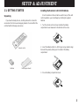
1-1. GETTING STARTED
Unpacking
If you haven’t already done so, carefully remove this unit and its
accessories from the box and wrapping material. You should find the
unit itself and the following accessories.
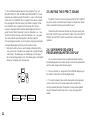
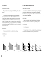
Installing the Remote Control Unit Batteries
Since the remote control unit will be used for many of this unit’s
control operations, you should begin by installing the supplied
batteries.
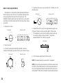
1. Turn the remote control unit over and slide the battery
compartment cover downward in the direction of the arrow.
2. Insert the batteries (LR6, AA, UM-3 type), being careful to align
them with the polarity markings on the inside of the battery
compartment.
3. Close the battery compartment cover.
3
SETUP & ADJUSTMENT
Remote control
Batteries User program sheets

●
When you notice that remote control operation has become
erratic, or the distance from which the remote control will function
has decreased, it’s time to replace the batteries. Always replace
all batteries at the same time.
●
Make sure that the YPC/USER/LEARN switch on the remote
control unit is set to the YPC or USER position for normal
operation.
●
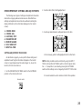
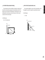
This remote control uses an advanced, highly directional infrared
beam. Be sure to aim the remote control directly at the remote
control sensor on the main unit when operating.
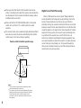
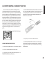
Remote control transmitter operation range
Notes
●
There should be no large obstacles between the remote
control transmitter and the main unit.
●
If the remote control sensor is directly illuminated by strong
lighting (especially an inverter type of fluorescent lamp etc.),
it might cause the remote control transmitter to work
incorrectly. In this case, reposition the main unit to avoid
direct lighting.
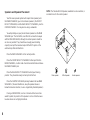
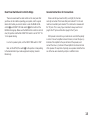
Digital Sound Field Processing
What is it that makes live music so good? Today’s advanced
sound reproduction technology lets you get extremely close to the
sound of a live performance, but chances are you’ll still notice
something missing, the acoustic environment of the live concert hall.
Extensive research into the exact nature of the sonic reflections that
create the ambience of a large hall has made it possible for Yamaha
engineers to bring you this same sound in your own listening room,
so you’ll feel all the sound of a live concert. What’s more, our
technicians, armed with sophisticated measuring equipment, have
even made it possible to capture the acoustics of a variety of actual
concert halls, jazz clubs, theaters, etc. from around the world, to
allow you to accurately recreate any one of these live performance
environments, all in your own home.
4
30°
30°
Infrared receiver
Within approximately
7 m (23 feet)

Dolby Pro Logic Surround
The Dolby Pro Logic Surround Decoder program lets you
experience the dramatic realism and impact of Dolby Surround movie
theater sound in your own home. Dolby Pro Logic gets its name from
its professional-grade steering logic circuitry, which provides greater
effective channel separation for a much higher degree of realism than
the “passive” Dolby Surround circuits found in today’s typical home
audio/video equipment. Dolby Pro Logic Surround provides a true
center channel, so that there are four independent channels, unlike
passive Dolby Surround, which has in effect only three channels: left,
right, and rear. This center channel allows listeners seated in even
less-than-ideal positions to hear the dialog originating from the action
on the screen while experiencing good stereo imaging.
This Dolby Pro Logic Surround Decoder employs a digital signal
processing system. This system improves the stability of sound at
each channel and crosstalk between channels, so that positioning of
sounds around the room is more accurate compared with
conventional analog signal processing systems.
In addition, this unit features a built-in automatic input balance
control. This always assures you the best performance without
manual adjustment.
Manufactured under license from Dolby Laboratories Licensing
Corporation. Additionally licensed under one or more of the
following patents: U.S. number 3,950,590; Canadian numbers
1,004,603 and 1,037,877. “Dolby”, “Pro Logic”, and the double-D
symbol are trademarks of Dolby Laboratories Licensing
Corporation.
Dolby Pro Logic Surround + DSP
You can also enjoy Dolby Pro Logic with two modes of Digital
Sound field processing. These combinations expand the surround
effect. One is the “ENHANCED” Dolby Pro Logic Surround, which
recreates the surround effect of the 35 mm film movie theater. The
other is the sound field program “MOVIE THEATER”, which recreates
the listening experience of a 70 mm film theater.
Directional Enhancement Circuit + DSP
The YAMAHA directional enhancement (DIR. ENHANCEMENT)
circuit expands and focuses the digital sound field.
This effect puts you in the midst of the action, while centering and
focusing your attention to the screen. This circuit is available on
Sound Field programs “CONCERT VIDEO” and “TV THEATER”.
5

Setting Up Your Speaker System
This unit has been designed to provide the best sound field
quality with a full seven-speaker system setup, using two extra pairs
of effect speakers to generate the sound field plus one center
speaker for dialog, when using Dolby Pro Logic Surround decoding.
We therefore recommend that you use a seven-speaker setup. A
four-speaker system using only one pair of effect speakers for the
sound field will still provide impressive ambience and effects,
however, and may be a good way to begin with this unit. You can
always upgrade to the full seven speaker system later. In the 4 or 5
speaker system, the Digital Sound Field Processing is still
performed, but the main speakers are used for both the main
channels and the front effect channels.
Use of the Center Dialog Speaker Is Recommended
With digital sound field programs No. 7 through No. 12, by using
either the Directional Enhancement circuit or the Dolby Pro Logic
decoder, decoded signals will be output from the center channel.
Therefore, if you want to upgrade the Audio/Video home theater
system, it is recommended to use the center speaker unit.
If for some reason it is not practical to use a center speaker, it is
possible to enjoy movie viewing without it. Best results, however, are
obtained with the full system.
It is also possible to further expand your system with the addition
of a subwoofer and amplifier. You may wish to choose the
convenience of a Yamaha Active Servo Processing Sub Woofer
System, which has its own built-in power amp.
6

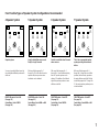
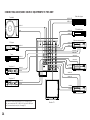
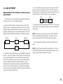
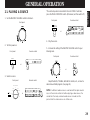
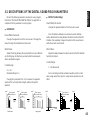
Four Possible Types of Speaker System Configurations Recommended
7
4 Speaker System
Simplest system.
You can enjoy widely diffused sound by
only adding two additional speaker units
at the rear.
FRONT MIX switch—Set to ON.
(See page 13.)
Center Mode—Set to PHNTM.
(See page 26.)
5 Speaker System
Good for Audio/Video sources and
Dolby Pro Logic Surround.
With sound field programs No. 7
through No. 12, which utilize the center
speaker effect, more precise center
localization can be obtained.
FRONT MIX switch—Set to ON.
(See page 13.)
Center Mode—Set to NRML or WD.
(See page 26.)
6 Speaker System
Good for sound fields from 2-channel
stereo sources.
With sound field programs No. 1
through No. 6, a sound effect matching
that of a 7-speaker system can be
obtained. The addition of front left and
right effect speakers produces a more
effective sound field.
FRONT MIX switch—Set to OFF.
(See page 13.)
Center Mode—Set to PHNTM.
(See page 26.)
7 Speaker System
This is the recommended speaker
system, providing the best sound
effects.
With sound field programs No. 1
through No. 6, using both sets of effect
speakers (front and rear), reproduces
the most effective sound field. With the
sound field programs No. 7 through No.
12, the center speaker provides precise
center localization.
FRONT MIX switch—Set to OFF.
(See page 13.)
Center Mode—Set to NRML or WD.
(See page 26.)

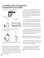
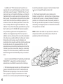
Speakers and Speaker Placement
Your full seven-speaker system will require three speaker pairs:
the MAIN SPEAKERS (your normal stereo speakers), the FRONT
EFFECT SPEAKERS, and the REAR EFFECT SPEAKERS, plus the
CENTER SPEAKER. You may also be using a subwoofer.
You will probably use your present stereo speakers as the MAIN
SPEAKER pair. The front effect, rear effect do not need to be equal
with the MAIN SPEAKERS, although the center speaker should be
as close as possible. They should have enough power handling
capacity to accept the maximum output of the DSP system or the
external amps that will drive them.
Place the MAIN SPEAKERS in the normal position.
Place the FRONT EFFECT SPEAKERS further apart than the
MAIN SPEAKERS, on either side of and a few feet behind and above
the MAIN SPEAKER pair.
Place the REAR EFFECT SPEAKERS behind your listening
position. They should be nearly six feet up from the floor.
Place the CENTER SPEAKER precisely between the two MAIN
SPEAKERS. (To avoid interference, keep the speaker above or
below the television monitor, or use a magnetically shielded speaker.)
If using a SUBWOOFER, such as a Yamaha Active Servo Sub-
woofer System, the position of the speaker is not so critical because
low bass tones are not highly directional.
NOTE: The Yamaha NS-C90 speaker, available in some countries, is
an ideal choice for the center speaker.
8
Main speaker Effect speaker Center speaker

VIDEO SUPERIMPOSE
If you connect your video cassette recorder, video disc player,
video monitor, etc. to this unit, you can take advantage of this unit’s
capability to display program titles, parameter data and information
about other various settings and adjustments on your video monitor’s
screen. This information will be superimposed over the video image.
If there is no video source connected or it is turned off, the
information will be displayed over a blue colored background (but no
video signal is input to this unit).
NOTE: The program titles, parameter data and other information are
also displayed on the display panel of this unit.
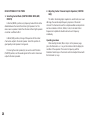
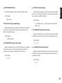
OPEN/CLOSE THE CONTROL DOOR
When it is not necessary to operate controls inside the control
door, close the door.
To close the door
To open the door
9
CONCERT HALL 1
Hall A in Europe

1-2. SETUP
Before you start making connections make sure all related electronic components are turned OFF.
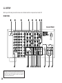
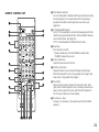
REAR PANEL
CAUTION: TO PREVENT ELECTRIC SHOCK, DO NOT USE THIS
(POLARIZED) PLUG WITH AN EXTENSION CORD, RECEPTACLE OR
OTHER OUTLET UNLESS THE BLADES CAN BE FULLY INSERTED
TO PREVENT BLADE EXPOSURE.
10
240V
1
9 0 A B
2 3 4 5 6 7 8
C D E
F
G H I J LK
(General Model)

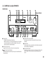
1 GND Terminal
Connects the ground wire of the turntable to produce minimum
hum. In some cases, however, better results may be obtained
with the ground wire disconnected.
2 Audio Signal Connection Jacks (for Audio Source Equipment)
Connect the inputs and/or outputs of your audio equipment.
3 Audio/Video Signal Connection Jacks (for Video Source
Equipment)
Connect the audio and video inputs and/or outputs of your video
equipment. In place of the VIDEO jacks, the S VIDEO jacks can
be used for higher resolution and improved picture quality if your
VCR, monitor, etc. are equipped with S-VIDEO connectors.
4 Main Speaker Terminals
When using this unit’s built-in main-channel amplifier, connect the
main speakers here. The jumper bars must be plugged in to
connect the MAIN IN jacks to the MAIN OUT jacks.
5 Front Effect Speaker Terminals
When using the built-in front-channel amplifier, connect the front
effect speakers here.
6 Center Speaker Terminals
When using the built-in center-channel amplifier, connect one or
two center speakers here.
7 Center Speaker Impedance Switch
Set to “A + B” when using two center speakers, or to “A or B”
when using only one center speaker.
8 Rear Effect Speaker Terminals
When using the built-in rear-channel amplifier, connect the rear
effect speakers here.
9 Video NTSC/PAL Switch (General Model only)
Set this switch to the position corresponding to the standard
that your video equipment employs.
0 Front Mix Switch
Set to “OFF” when setting up a full 7 or 6 speaker system, or to
“ON” when setting up a 5 or 4 speaker system.
A Main Level Control
Adjusts the main-channel line output level at the MAIN OUT
jacks. Used to achieve balance between the main and effect
speakers.
B Main Out Jacks
Main-channel line output. Connected with jumper bars to MAIN
IN jacks when the built-in amplifier is used. Connected to input
jacks of external stereo power amplifier (MAIN IN or TAPE PLAY
jacks of integrated amplifier or receiver) when using external
amplification.
C Main In Jacks
Line input to built-in main-channel amplifier. Connected with
jumper bars to MAIN OUT jacks when the built-in amplifier is
used. Not connected when using an external power amplifier.
D Center Out Jacks
Center-channel line outputs. Not connected when the built-in
amplifier is used. Can be connected to input jack(s) of one or two
external power amplifier(s) to drive the center speaker(s).
11

E Center In Jack
Line input to built-in center-channel amplifier. Connected with
jumper bars to CENTER OUT jack when the built-in amplifier is
used. Not connected when using an external power amplifier.
F Mono Low Pass Jack
When using a subwoofer, connect its amplifier input to this jack.
Frequencies below 200 Hz from the left main, right main and
center channels are output to this jack.
G Split Low Pass Jacks
When using two subwoofers, connect their amplifiers to these
jacks. Frequencies below 200 Hz from the left main and center
channels are output (in 10:7) to the SPLIT L jack, and also
frequencies below 200 Hz from the right main and center
channels are output (in 10:7) to the SPLIT R jack.
H Front Effect Out Jacks
Front-channel line output. Not connected when the built-in
amplifier is used. Can be connected to input jacks of an external
stereo power amplifier driving the front effect speakers.
I Rear Effect Out Jacks
Rear-channel line output. Not connected when the built-in
amplifier is used. Can be connected to input jacks of an external
stereo power amplifier driving the rear effect speakers.
J Voltage Selector (General Model only)
Be sure to set to the line voltage in your area before applying
power. Consult your dealer if unsure of the correct setting.
K Switched AC Outlets
You may plug other audio components into these sockets as long
as their combined power consumption does not exceed the
specified value shown. “Switched” means that these components
are turned on and off by this unit’s power switch.
L Unswitched AC Outlet (U.S.A., Canada, and General Model)
The total power consumption of audio components plugged into
this socket should not exceed the specified value shown.
“Unswitched” means that power is available even when this unit is
off.
NOTE: If an external power amplifier is connected to the front effect
or rear effect output jacks, the corresponding internal amplifier will be
turned off and no output will be available at the speaker terminals.
12

Rear Panel Switch and Control Settings
There are several switches and controls on the rear panel that
you’ll have to check before operating your system, and it’s a good
idea to do it before you connect cables. Locate the MAIN LEVEL
control (A) and FRONT MIX slide switch (:) at the bottom of the
MAIN terminal group. Make sure the MAIN LEVEL control is set to its
max (10) position and that the FRONT MIX switch is set to “OFF” for
7 or 6 speaker driving.
In a 5 or 4 speaker system, set the FRONT MIX switch to “ON”.
Next, set the NTSC/PAL switch (9) to the position corresponding
to the standard which your video equipments employ. (General
Model only)
General Instructions for Connections
Make sure that you have the left (L) and right (R) channels
correctly connected. That means that jacks marked “L” on this unit
must be connected to jacks marked “L” on other units. Likewise with
the “R” jacks. This is easy if you remember to always use the red
plug for the “R” jacks and the other plugs for the “L” jacks.
With speaker connections you must also be sure that the polarity
is correct. For each amplifier and each channel, connect the plus (+)
terminal of the amplifier to the plus terminal of the speaker, and
connect the minus (–) terminal of the amplifier to the minus terminal
of the speaker. To keep track of polarity, use a speaker cable that has
one of the two wires marked by a stripe or a different color.
13

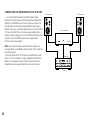
CONNECTING AUDIO/VIDEO SOURCE EQUIPMENTS TO THIS UNIT
If you wish to connect a second monitor TV (or a projector) to this
unit, you can switch the VCR 3 VIDEO OUT jack (and S VIDEO jack
also) to a second monitor out jack. (See page 27.)
14
OUTPUT
OUTPUT
OUTPUT
LINE OUT
LINE IN
AUDIO OUT
VIDEO OUT
AUDIO OUT
VIDEO OUT
VIDEO IN
AUDIO IN
VIDEO IN
AUDIO IN
VIDEO OUT
AUDIO OUT
AUDIO OUT
VIDEO OUT
AUDIO OUT
VIDEO OUT
AUDIO OUT
VIDEO OUT
LINE OUT
LINE IN
GND
Turntable
CD player
Tuner
Tape deck 1
Tape deck 2
Monitor TV
Video disc player
TV/Satellite tuner
Video cassette recorder 1
Video cassette recorder 2
Video cassette recorder 3

CONNECTING TO S VIDEO JACKS
If your video cassette recorder, video disc player, etc. and your
monitor are equipped with “S” (high-resolution) video terminals,
connect them to this unit’s S VIDEO jacks, and connect this unit’s
S VIDEO MONITOR OUT jack to the “S” video input of your monitor.
Otherwise, connect the composite video jacks from your video
cassette recorder, video disc player, etc. to the VIDEO jacks of this
unit, and connect this unit’s VIDEO MONITOR OUT jack to the
composite video input of your monitor.
NOTE: If video signals are sent to both S VIDEO input and VIDEO
input jacks, the signals will be sent to their respective output jacks
independently.
NOTE: If your unit is the General Model, be sure the VIDEO
NTSC/PAL switch has been correctly set to the standard that your
video equipments employ. U.S. and Canadian models have no switch
and use the NTSC standard, while other models without a switch use
the PAL standard.
Notes about the Video superimpose
●
If you watch a video source that is connected to both S VIDEO and
VIDEO input jacks of this unit, signals of screen display information
are output from only the S VIDEO MONITOR OUT jack.
●
When no video signal is input to either S VIDEO or VIDEO input
jacks of this unit, signals of screen display information are output
from both S VIDEO MONITOR OUT and VIDEO MONITOR OUT
jacks with a color background.
* For the General Model, if the NTSC/PAL switch on the rear panel
is set to “PAL”, nothing will be output from either S VIDEO
MONITOR OUT or VIDEO MONITOR OUT jack in this case.
15
VIDEO
OUT
VIDEO OUT
S-VIDEO OUT
VIDEO IN
S-VIDEO IN
VIDEO IN
S-VIDEO
IN
S-VIDEO OUT
VIDEO OUT
VIDEO IN
VIDEO IN
S-VIDEO IN
S-VIDEO IN
S-VIDEO OUT
VIDEO OUT
S-VIDEO
OUT
VIDEO
OUT
S-VIDEO
OUT
Video disc player
Video cassette recorder 2
TV/Satellite tuner
Video cassette recorder 1
Video cassette recorder 3
Monitor TV

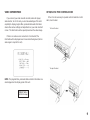
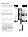
CONNECTING THE MAIN SPEAKERS TO THIS UNIT
Connect the MAIN speakers to the MAIN speaker output
terminals of this unit. Make sure that the jumper bars between the
MAIN OUT and MAIN IN jacks on the rear panel are in place. It is
also possible to use an external power amplifier if more power is
desired. In this case, remove the jumper bars and connect the MAIN
OUT jacks to the INPUT jacks of a stereo power amplifier with a
stereo pin cable—making sure to connect the left and right channels
correctly. Connect the MAIN speakers to the speaker output
terminals of the power amplifier.
NOTE: If an external amplifier is used for the main speakers, it is
recommended to use the MAIN speaker terminals of this unit for the
rear effect speakers.
Connect the REAR EFFECT OUT jacks to the MAIN IN jacks with
the pin cord. This combination is highly upgraded and ideal for the
division of sound quality, because the rear channel output of the
Audio/Video system is equally important as the center channel.
16
INPUT
MAIN UNIT
Main speaker
Power amplifier
This unit
Main speaker

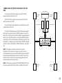
CONNECTING THE EFFECT SPEAKERS TO THIS
UNIT
Connect the FRONT effect speakers to the FRONT effect
speaker output terminals of this unit.
If the FRONT effect speakers are not used, the FRONT MIX
switch should be set to “ON”.
Connect the REAR effect speakers to the REAR effect speaker
output terminals of this unit.
Connect the CENTER speaker to the CENTER speaker output
terminals. If you will be using one CENTER speaker, connect it to
either the A or B terminals and set the CENTER speaker impedance
switch to “A or B” (bottom position). If using two CENTER speakers,
connect them to the A and B terminals, and set the switch to “A + B”
(top position). If, however, you will not be using a CENTER speaker,
be sure to set the Center Mode to “PHNTM” (phantom). (See page
25.)
NOTE: The speaker connections above are fine for most
applications. If for some reason, however, you wish to use an
external power amp for any or all of the effect channels, connect the
line level output jack(s) for each channel to the INPUT jacks of the
external amp and connect the corresponding speaker pair to the
speaker terminals of the external amp.
NOTE: If the pin plug is inserted in the FRONT/REAR EFFECT out
jacks, the speaker output from the built-in amplifier will be cut off.
17
LR
LR
Front effect
speaker
Rear effect
speaker
Front effect
speaker
Rear effect
speaker
This unit
Center speaker Center speaker
Center speaker

ADDING A SUBWOOFER
You may wish to add a subwoofer to reinforce the bass
frequencies.
This unit provides line-level subwoofer outputs, which contain only
the frequencies under 200 Hz from the main and center channels. If
you use one subwoofer, connect the MONO LOW PASS jack to the
INPUT jack of the subwoofer amplifier, and connect the speaker
terminals of the subwoofer amplifier to the subwoofer.
If you wish to obtain more presence in your listening room, the
use of two subwoofers is recommended. To connect two subwoofers
to this unit, connect the “left” SPLIT LOW PASS jack to the INPUT
jack of the amplifier driving the left subwoofer, and the “right” SPLIT
LOW PASS jack to the INPUT jack of the amplifier driving the right
subwoofer, and then connect each subwoofer to the corresponding
amplifier.
With some subwoofers, including the Yamaha Active Servo
Processing Subwoofer System, the amplifier and subwoofer are in
the same unit.
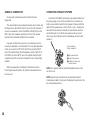
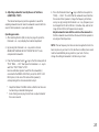
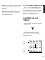
CONNECTING SPEAKER SYSTEMS
Connect the SPEAKERS terminals to your speakers with wire of
the proper gauge, cut as short as possible. If the connections are
faulty, no sound will be heard from the speakers. Make sure that the
polarity of the speaker wires is correct, that is, + and – markings are
observed. If these wires are reversed, the sound will be unnatural
and will lack bass. Do not let the bare speaker wires touch each
other or any other metal part as this could damage this unit and/or
speakers.
Red: positive (+)
Black: negative (–)
1 Unscrew the knob.
2 Insert the bare wire.
3 Tighten the knob and
secure the wire.
NOTE: Use speakers with the specified impedance shown on the
rear of this unit.
NOTE: Banana Plug connections are also possible (except for
Scandinavian models). Simply insert the Banana Plug connector into
the corresponding terminal.
18
2
3
1
La pagina si sta caricando...
La pagina si sta caricando...
La pagina si sta caricando...
La pagina si sta caricando...
La pagina si sta caricando...
La pagina si sta caricando...
La pagina si sta caricando...
La pagina si sta caricando...
La pagina si sta caricando...
La pagina si sta caricando...
La pagina si sta caricando...
La pagina si sta caricando...
La pagina si sta caricando...
La pagina si sta caricando...
La pagina si sta caricando...
La pagina si sta caricando...
La pagina si sta caricando...
La pagina si sta caricando...
La pagina si sta caricando...
La pagina si sta caricando...
La pagina si sta caricando...
La pagina si sta caricando...
La pagina si sta caricando...
La pagina si sta caricando...
La pagina si sta caricando...
La pagina si sta caricando...
La pagina si sta caricando...
La pagina si sta caricando...
La pagina si sta caricando...
La pagina si sta caricando...
La pagina si sta caricando...
La pagina si sta caricando...
La pagina si sta caricando...
La pagina si sta caricando...
La pagina si sta caricando...
La pagina si sta caricando...
-
 1
1
-
 2
2
-
 3
3
-
 4
4
-
 5
5
-
 6
6
-
 7
7
-
 8
8
-
 9
9
-
 10
10
-
 11
11
-
 12
12
-
 13
13
-
 14
14
-
 15
15
-
 16
16
-
 17
17
-
 18
18
-
 19
19
-
 20
20
-
 21
21
-
 22
22
-
 23
23
-
 24
24
-
 25
25
-
 26
26
-
 27
27
-
 28
28
-
 29
29
-
 30
30
-
 31
31
-
 32
32
-
 33
33
-
 34
34
-
 35
35
-
 36
36
-
 37
37
-
 38
38
-
 39
39
-
 40
40
-
 41
41
-
 42
42
-
 43
43
-
 44
44
-
 45
45
-
 46
46
-
 47
47
-
 48
48
-
 49
49
-
 50
50
-
 51
51
-
 52
52
-
 53
53
-
 54
54
-
 55
55
-
 56
56


Yamaha DSP-A2070 Manuale del proprietario
- Categoria
- Ricevitori AV
- Tipo
- Manuale del proprietario
in altre lingue
- English: Yamaha DSP-A2070 Owner's manual
- français: Yamaha DSP-A2070 Le manuel du propriétaire
- español: Yamaha DSP-A2070 El manual del propietario
- Deutsch: Yamaha DSP-A2070 Bedienungsanleitung
- русский: Yamaha DSP-A2070 Инструкция по применению
- Nederlands: Yamaha DSP-A2070 de handleiding
- português: Yamaha DSP-A2070 Manual do proprietário
- dansk: Yamaha DSP-A2070 Brugervejledning
- čeština: Yamaha DSP-A2070 Návod k obsluze
- polski: Yamaha DSP-A2070 Instrukcja obsługi
- svenska: Yamaha DSP-A2070 Bruksanvisning
- Türkçe: Yamaha DSP-A2070 El kitabı
- suomi: Yamaha DSP-A2070 Omistajan opas
- română: Yamaha DSP-A2070 Manualul proprietarului
Documenti correlati
-
Yamaha DSP-E580 Manuale del proprietario
-
Yamaha DSP-A1092 Manuale del proprietario
-
-
-
-
-
-
-
-
