
Mobile Communications
LBI-38407D
Operator’s Manual
EDACS
M-PA
PORTABLE RADIOS

Copyright
©
May 1991, Ericsson Mobile Communications AB
Table of Contents
INTRODUCTION . . . . . . . . . 5
CONTROLS . . . . . . . . . . . 7
ON/OFF SWITCH . . . . . . . 7
VOLUME CONTROL KNOB . . 7
CONTROL KNOB . . . . . . . 7
PTT BUTTON . . . . . . . . . . 8
MONITOR BUTTON . . . . . . 8
Trunked Mode . . . . . . . . 8
Conventional Mode . . . . . . 8
EMERGENCY BUTTON . . . . 9
STEP BUTTON
(Scan And System Models Only) 9
SCAN BUTTON
(Scan And System Models Only) 10
Table of Contents
(Continued)
SPC BUTTON
(Scan And System Models Only) 10
2nd BUTTON
(Scan And System ModeIs Only) 11
ADD/DELETE BUTTON
(Scan And System Models Only) 11
LOCK BUTTON
(Scan And System ModeIs Only) 11
STO BUTTON (Shifted Digit 1 -
System Model Only) . . . . . . 11
RCL BUTTON (Shifted Digit 3 -
System Model Only) . . . . . . 12
CLR BUTTON (Shifted # Button-
System Model Only) . . . . . . 12
STS BUTTON (Shifted Digit -
System Model Only) . . . . . . 12
INDICATORS . . . . . . . . . . . 12
UNIVERSAL DEVICE
CONNECTOR . . . . . . . . . . 14
ALERT TONES . . . . . . . . . . 14
OPERATION . . . . . . . . . . . 15
POWER-UP . . . . . . . . . . 15
SYSTEM/GROUP/CHANNEL
SELECTION . . . . . . . . . . 15
This manual is published by
Ericsson GE Mobile
Communications Inc.
, without any warranty. Im-
provements and changes to this manual necessitated
by typographical errors, inaccuracies of current infor-
mation, or improvements to programs and/or equip-
ment, may be made by
Ericsson GE Mobile
Communications Inc.
, at any time and without no-
tice. Such changes will be incorporated into new
editions of this manual. No part of this manual may be
reproduced or transmitted in any form or by any
means, electronic or mechanical, including photo-
copying and recording, for any purpose, without the
express written permission of
Ericsson GE Mobile
Communications Inc.
2

Table of Contents
(Continued)
STEP Button Programmed For
System Selection; CONTROL
KNOB Programmed For Group
And Channel Selection . . . . 16
CONTROL KNOB Programmed
For System Selection; STEP
Button Programmed For Group
And Channel Selection . . . . 17
TRUNKED MODE OPERATION 17
Receiving A Message . . . . . 17
Sending A Message . . . . . . 19
Emergency Operation
(Trunked Mode) . . . . . . . . 19
Dynamic Regrouping . . . . . 20
Wide Area System Scanning . 20
Scanning Trunked Groups (Scan
And System Models Only) . . . 21
SpeciaI CaIIs . . . . . . . . . 22
SYSTEM MESSAGE OPERATION
(System Model Only) . . . . . . 27
CONVENTIONAL MODE
OPERATION . . . . . . . . . . . 27
Receiving A Message . . . . . 27
Sending A Message . . . . . . 28
Emergency Operation
(Conventional Mode) . . . . . 29
Scanning Conventional
Channels (Scan And System
Models Only) . . . . . . . . . . 29
Table of Contents
(Continued)
Telephone Interconnect
Calls (Scan And System
ModeIs Only) . . . . . . . . . 31
OPERATING TIPS . . . . . . . . 31
OPERATING RULES
AND REGULATIONS . . . . . . . 32
BATTERY PACKS . . . . . . . . . 33
INSTALLING THE BATTERY
PACK . . . . . . . . . . . . . . 33
REMOVING THE BATTERY
PACK . . . . . . . . . . . . . . 33
CHARGING THE BATTERY
PACKS . . . . . . . . . . . . . . 34
RECHARGEABLE BATTERY
PACK DISPOSAL . . . . . . . . 35
SWIVEL MOUNT REMOVAL AND
REPLACEMENT . . . . . . . . . . 35
INTRINSICALLY SAFE USAGE . . 36
BATTERY PACKS . . . . . . . . 36
ACCESSORIES . . . . . . . . . 37
WARRANTY . . . . . . . . . . . . 38
NICKEL-CADMIUM BATTERY
WARRANTY . . . . . . . . . . . . 39
3

CONTROLS
ON/OFF SWITCH
The ON/OFF SWITCH is located on
the battery pack. Sliding this switch up will
supply power to the radio from the battery
pack. An audible click will be heard and
the ‘ON" indicator will be exposed. When
the radio is turned on, it will perform a
power-up self test and resume operating
on the previous group or channel. Sliding
the switch down will turn the radio off.
VOLUME CONTROL KNOB
The VOLUME CONTROL KNOB is a
rotatable control on the top of the radio
used to adjust the receiver’s volume level
in the speaker. Rotating this knob in a
clockwise direction will increase the vol-
ume and counter-clockwise rotation will
decrease the volume. Minimum volume
levels can be programmed into the radio to
prevent missed calls when the knob is
rotated fully counter-clockwise.
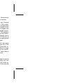
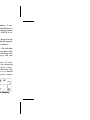
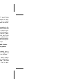
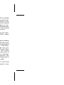
CONTROL KNOB
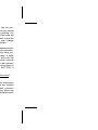
Figure 1 - Side View (All Models)
Figure 2 - Select Model
4

INTRODUCTION
The EDACS M-PA Select, Scan
and System model radios are high-quality
microprocessor-controlled synthesized
two-way FM portable radios. These full-
featured radios are designed for operation
in EDACS (Enhanced Digital Access Com-
munications System) trunking systems
and conventional radio systems. M-PA op-
eration is highlighted by the radio’s pro-
gramming versatility. This permits custom
operation of each radio to meet the needs
of the radio system and the individual us-
ers.
This manual describes operating pro-
cedures for the three (3) different radio
models.
The M-PA Select model radio is the
basic version of the radio that can be pro-
grammed with up to sixteen (16) inde-
pendent trunked groups and/or
conventional radio channels. This unit fea-
tures an eight-digit alphanumeric liquid
crystal display (LCD) and a 16-position
knob for group/channel selection. The dis-
play also has status flags that indicate
various operating modes and it is backlit
for nighttime and low-level ambient light
operation.
Scan and System model radios have
an LCD similar to the Select model radio.
These radios have front panel keypads
that provide additional operating features
not available on the Select model radio.
The Scan model radio has a 4-button key-
pad and the System model radio has a
16-button keypad. Additional features in-
clude expanded system and group/chan-
nel selection capability, trunked group and
conventional channel scan capability,
trunked mode individual call capability, and
telephone interconnect call capability. The
numeric keypad on the System model ra-
dio also allows storage of ten (10) opera-
tor-entered telephone numbers and ten
(10) operator-entered radio ID numbers.
These numbers can be recalled at will and
initiated. Manually dialed telephone inter-
connect with overdial capability and con-
ventional mode DTMF dialing is also
provided by the System model’s 16-button
keypad.
5

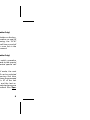
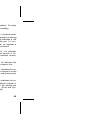
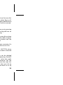
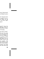
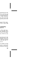
Figure 3 - Scan Model
Figure 4 - System Model
6

The rotatable 16-position CONTROL
KNOB located on the top of the radio pro-
vides system, group or channel selection
according to how the radio is programmed.
A stop plate may be installed under the
knob to limit the maximum number of po-
sitions to less than sixteen (16). It is nor-
mally factory installed for fifteen (15)
positions.
On the Select model radio, the CON-
TROL KNOB selects any one of trunked
systems and groups or conventional chan-
nels programmed into the radio.
On Scan and System model radios,
the CONTROL KNOB is used in combina-
tion with the keypad to select a specific
trunked system and group or a conven-
tional channel. The selection method is
determined by the radio’s programming.
See the section entitled "SYS-
TEM/GROUP/CHANNEL SELECTION" in
the "OPERATION" section of this manual
for details.
PTT BUTTON
Pressing the PTT BUTTON on the
side of the radio turns on the radio‘s trans-
mitter. The "TX" status flag in the display
will turn on when the radio is transmitting.
Releasing the PTT BUTTON will return
operation to receive mode.
When operating on a trunked system,
the radio may be programmed to automat-
ically transmit (without the operator press-
ing the PTT BUTTON) to maintain
communication with the site controller. The
"TX" status flag in the display will turn on
when the radio is transmitting.
MONITOR BUTTON
Trunked Mode
The exact operation of a particular ra-
dio will vary depending upon its mode of
operation, its programming, and the par-
ticular radio system. Consult a radio sys-
tem’s representative for particular features
that are programmed into the radio.
The radio operates in trunked mode
when a trunked system is selected and it
operates in conventional mode when a
conventional system is selected.
7

When operating on a trunked system
in special call mode, pressing the MONI-
TOR BUTTON after an individual call has
been received will return the radio to the
group call mode. In this condition, the radio
will not respond on an individual basis but
it will then transmit group calls upon sub-
sequent activations of the PTT BUTTON.
The radio will also automatically return to
the group call mode after the programmed
individual call-back time-out period ex-
pires.
This button is also used to toggle be-
tween group and regroup settings if the
Dynamic Regrouping mode (with deselect
capability) has been activated by the site
controller.
On the System model radio, pressing
the MONITOR BUTTON will clear all digits
entered from the numeric keypad and re-
turn the radio to the selected group display.
Conventional Mode
When the radio is operating in conven-
tional mode (on a conventional channel),
the MONITOR BUTTON is used to tempo-
rarily unsquelch the receiver so channel
traffic can be monitored. Momentarily
pressing it will unsquelch the receiver.
If the selected channel has Channel
Guard (CG) and/or Type 99 (T99) coded-
squelch tone decode feature programmed
for the selected channel, this button is can
also be used to enable and disable the
programmed feature. Repeated activa-
tions will toggle CG and/or T99 between
the enabled (on) and disabled (off) states.
To toggle the programmed feature, press
and hold the MONITOR BUTTON for at
least two (2) seconds until the appropriate
status flag in the display toggles.
The MONITOR BUTTON is also used
to reset the radio after a Type 99 (T99)
selective call has been successfully re-
ceived. If the radio is operating in a Type
99 mode, momentarily press the MONI-
TOR BUTTON to reset the radio after a
T99 call is successfully received.
EMERGENCY BUTTON
When the radio is operating in trunked
mode, pressing and holding the red
EMERGENCY BUTTON on top of the ra-
dio for approximately one (1) second will
8

initiate an emergency call on the pro-
grammed home group. If no home group
is programmed into the radio the emer-
gency call will be transmitted on the se-
lected group.
In conventional mode, initiating an
emergency call by pressing the EMER-
GENCY BUTTON will cause the radio to
transmit GE-STAR emergency signaling
on the programmed emergency channel.
If no emergency channel is programmed,
GE-STAR emergency signaling will be
transmitted on the selected channel.
STEP BUTTON
(Scan And System Models Only)
The STEP button located on the key-
pad can be programmed to select trunked
groups and conventional channels or it can
be programmed to select systems. See the
section entitled "SYSTEM/GROUP/
CHANNEL SELECTION" for details.
STEP is also used to scroll through the
programmed special call table when the
special call mode is enabled.
SCAN BUTTON
(Scan And System Models Only)
Pressing the SCAN button on the key-
pad will toggle scan operation on and off
When the radio is scanning, the "SCN"
status flag in the display will turn on and all
groups/channels on the scan list in the
current system will be scanned.
SPC BUTTON
(Scan And System Models Only)
Pressing SPC will switch operation
from the group select mode to the special
call mode. The last selected special call
will be displayed.
While in special call mode, the next
programmed special call can be selected
by pressing STEP. Pressing 2nd then
STEP will select the previous programmed
special call. The caller’s ID of the last
received individual call and the last re-
ceived group call on the selected group are
a selectable using this method. See "
Spe-
cial Calls" for details.
9

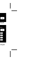
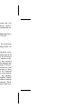
2nd BUTTON (Scan And System
ModeIs Only)
On an M-PA Scan model radio the two
(2) center buttons (SCAN and SPC) on the
keypad are dual-function buttons. The
second or shifted functions are accessed
by first pressing the blue 2nd button. The
SCAN button’s second function is scan
add/delete for scan list updating. The sec-
ond function for the SPC button is the
keypad lock feature.
On an M-PA System model radio, six
(6) of the buttons on the keypad are dual-
function buttons. Press and release the
blue 2nd function button to shift keypad
selection to the scan add/delete (SCAN
button), the keypad lock feature (SPC but-
ton), STO, RCL, CLR, or STS buttons.
ADD/DELETE BUTTON
(Scan And System Models Only)
When in trunked mode, pressing and
releasing 2nd and then pressing A/D
(shifted SCAN button) will toggle the se-
lected group on and off the scan list. When
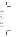
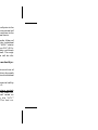
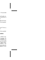
Figure 6 - System Model Keypad
Figure 5 - Scan Model Keypad
10

the selected group is on the scan list, the
‘S" status flag will show in the display.
In conventional mode, pressing and
releasing 2nd and then pressing A/D
(shifted SCAN button) will scroll the se-
lected channel’s scan priority between
non-priority scan ("S" status flag), priority-
two scan ("2" status flag), priority-one scan
("1" status flag) and no scan (no status
flags).
Scan must be turned off("SCN" status
flag off) before groups or channels can be
added to or deleted from the scan list.
LOCK BUTTON
(Scan And System ModeIs Only)
The radio’s keypad can be locked to
prevent accidental activations. To lock the
keypad, simultaneously press the 2nd and
LOCK (shifted SPC); "LOCKED" will be
displayed when the keypad is locked. To
unlock the keypad, press the 2nd and
LOCK buttons again; ‘UNLOCKED" will be
displayed momentarily.
STO BUTTON
(Shifted Digit 1 - System Model Only)
STO (shifted digit 1) allows ten (10)
telephone numbers and ten (10) radio ID
numbers to be stored and later recalled
with the RCL button.
Store a telephone number by entering
the number (up to 29 digits) followed by an
asterisk (*). Next, enter the storage loca-
tion (1 - 10) and press and release 2nd and
then press STO. "STORED" will be dis-
played for two seconds.
Store individual radio ID numbers by
entering the ID number (1 - 16382) fol-
lowed by a pound sign (#). Next enter the
storage location (1 - 10) and press and
release 2nd and then press STO.
‘STORED’ will be displayed for two sec-
onds.
RCL BUTTON
(Shifted Digit 3 - System Model Only)
RCL allows the previously stored tele-
phone or radio ID numbers to be recalled.
To recall a number first enter an * or # (*
for telephone number, # for radio ID num-
ber) and then enter the storage location (1
- 10). Next press and release 2nd and then
11

press RCL and the recalled number will be
displayed.
CLR BUTTON
(Shifted # Button-System Model Only)
To clear the last digit entered, press
and release 2nd and then press CLR
(shifted # button). Holding CLR down will
repetitively clear previous digits. The radio
will return to the last operating state when
all entered digits are cleared.
STS BUTTON
(Shifted Digit - System Model Only)
The STS button will be used for future
status operations.
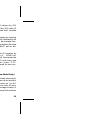
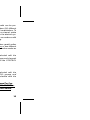
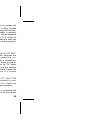
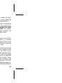
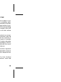
INDICATORS
The radio’s liquid crystal display (LCD)
located on the front panel has eight (B)
alphanumeric characters and various
status flags located above and below the
alphanumeric characters. This display
provides indications of the current operat-
ing system, group or channel and it dis-
plays various other messages such as
special call ID names or numbers, and
telephone interconnect numbers. If pro-
grammed on, LCD backlighting will turn on
for a short period anytime an active button
is pressed or the CONTROL KNOB is ro-
tated.
The status flags located along the top
and bottom of the display indicate operat-
ing modes and conditions as follows:
EMG EMerGency mode - On indicates
an emergency call has been initi-
ated by the user. Flashing indi-
cates an emergency call has
been received.
NC No Control channel- On indi-
cates the radio is not receiving
the trunked control chan-
nel. Flashing indicates the
trunked system is in a failsoft
condition (supervisory radios
only).
HI
Figure 7 - Liquid Crystal Display
12

HIgh power transmit - On indi-
cates the selected system or
channel has been pro-
grammed for high power transmit
operation. Off indicates low
power transmit.
MSG MeSsaGe - Flashing indicates
an individual call has been re-
ceived (trunked mode).
T99 Type 99 tone decode - On indi-
cates Type 99 tone decoding is
enabled on the seIected conven-
tional channel. Flashing in-
dicates a T99 selective call has
been received and the radio
must be reset to receive another
T99 call.
CNV CoNVentional mode - On indi-
cates the radio is operating in the
conventional mode.
SPC SPecial Call mode - On indicates
the special call mode has been
enabled. (Scan and System
models only).
TX
Transmitter enabled - On when
the radio is transmitting.
BSY BuSY - When in trunked mode,
on indicates the radio is receiving
a call; flashing indicates a call
has been queued. In con-
ventional mode, on indicates a
carrier is being received.
CG Channel Guard - On indicates
Channel Guard decode is en-
abled on the selected conven-
tional channel.
BAT BATtery low - On indicates the
battery pack’s charge is low.
S Scan list - On indicates the se-
lected group or channel is on the
scan list (Scan and System mod-
els only).
1 priority 1 - On indicates the se-
lected conventional channel is
designated as the priority-one
scan channel. (Scan and Sys-
tem models only).
2
13

priority 2 - On indicates the se-
lected conventional channel is
designated as the priority-two
scan channel. (Scan and Sys-
tem models only).
SCN SCaN mode - On indicates the
radio is scanning. (Scan and
System models only).
UNIVERSAL DEVICE CONNECTOR
The Universal Device Connector
(UDC) is Iocated on the side of the radio-
just above the PTT and MONITOR BUT-
TONS. This connector provides con-
nections for the external accessories such
as a headset, a speaker-mike, or an emer-
gency lanyard. When the radio is locked in
a vehicular charger/repeater the UDC pro-
vides the audio and control connections
between the radio and the vehicular
charger/repeater. The UDC is also used by
the maintenance personnel when the radio
is programmed.
ALERT TONES
The radio sounds three (3) basic alert tones
or "beeps" to indicate various operating
conditions. Alert tones may be pro-
grammed to remain off at all times.
500 Hz Tone - trunked failure tone
sounds when a
trunked failure has oc-
curred (call denied,
failed confirmation).
1000 Hz Tone - key pressed - sounds
when a button is
pressed and a status
change occurs.
- channel access tone
sounds when a
trunked channel has
been assigned and it is
clear to talk.
- low battery sounds
when the battery
pack’s charge is low.
2500 Hz Tone - call queued tone
sounds when a
trunked call is queued.
14

OPERATION
POWER-UP
After the battery pack and antenna
have been installed, turn the radio on by
sliding the ON/OFF SWITCH on the bat-
tery pack up. After the radio has completed
a power-up self-test, it will begin opera-
tion on the last operating state as dis-
played in the LCD. If programmed on, the
power-up alert tone (beep) will be heard.
If the radio was previously operating in
a trunking system and communication with
this system’s control channel cannot be
established, the "NC" status flag will turn
on. This may occur if, for example, the
radio is out of range of the previous trunk-
ing site. It may be necessary to move to
another location, select another trunking
system, or a conventional channel.
SYSTEM/GROUP/CHANNEL SELEC-
TION
The Select model radio can be pro-
grammed with up to sixteen (16) different
system/group or channel combinations. To
select a particular group or channel, rotate
the CONTROL KNOB to the desired sys-
tem/group or channel in accordance with
the radio ‘s programming.
The Scan and System model radios
are programmed with
one of two different
system/group/channel selection modes as
follows:
•
Systems are selected with the
STEP button; groups and channels
are selected with the CONTROL
KNOB.
or
•
Systems are selected with the
CONTROL KNOB; groups and
channels are selected with the
STEP button.
STEP Button Programmed For Sys-
tem Selection; CONTROL KNOB Pro-
grammed For Group And Channel
Selection
15

System Selection
Press and release STEP to select the
next trunked system programmed into the
radio as indicated in the display. To select
the previous system, press and release
2nd and then press STEP. Holding down
STEP will cause the radio to automatically
scroll through the system list One or more
of the systems may be programmed for
conventional mode operation. Upon
reaching an end of the system list, the
radio may be programmed to stop selec-
tion or wrap around (go from one end to
the other).
On the System model radio, systems
can also be selected by entering the sys-
tem number from the numeric keypad and
then pressing STEP. If a number out of the
programmed range is entered, "RANGE"
will be displayed.
Group/Channel Selection
After the desired system is selected
with the STEP button, rotate the CON-
TROL KNOB to the desired trunked group
or conventional channel as indicated in the
display A stop-plate may be placed under
the knob to limit the maximum positions to
less than sixteen (16).
CONTROL KNOB Programmed For
System Selection; STEP Button Pro-
grammed For Group And Channel Se-
lection
System Selection
Rotate the CONTROL KNOB to the
desired trunked system as indicated in the
display. One or more of the systems
maybe programmed for conventional
mode operation. A stop-plate may be
placed under the knob to limit the maxi-
mum positions to less than sixteen (16).
Group/Channel Selection
After the desired system is selected
with the CONTROL KNOB, press and re-
lease STEP to select the next trunked
group or conventional channel pro-
grammed into the radio as indicated in the
display To select the previous group or
channel, press and release 2nd and then
press STEP. Holding down STEP will
cause the radio to automatically scroll
through the group/channel list. Upon
reaching an end of the group/channel list,
16

the radio may be programmed to stop se-
lection or wrap around (go from one end to
the other).
On the System model radio, groups or
channels can also be selected by entering
the group/channel number from the nu-
meric keypad and then pressing STEP. If
a number out of the programmed range is
entered, ‘RANGE’ will be displayed.
TRUNKED MODE OPERATION
Digital trunking provides fast commu-
nication access. In this mode the operator
selects a communication system and
group and the communication channel is
allocated through digital signalling with the
site.
Receiving A Message
1. Slide the ON/OFF SWITCH on
the battery pack up to the on
position. The radio will initiate
and complete the power-up self-
test then the system’s name and
"NC" status flag will be displayed
until a control channel is located.
When the control channel is lo-
cated, the "NC" status flag dis-
appears and the group name is
displayed.
2. Adjust the VOLUME CONTROL
to an approximate mid-range po-
sition.
3. Select the desired system and
group. See the section entitled
"SYSTEM/GROUP/CHANNEL
SELECTION" operating proce-
dures for details. The dis-
play indicates the selected
group.
4. The radio is now ready to receive
messages.
5. GROUP CALL - When a group
call is received, the radio un-
squelches on the assigned
channel and the "BSY" status
flag turns on. The group name or
the originator’s ID (depending on
programming) is displayed. Ad-
just the volume as necessary.
17

INDIVIDUAL CALL - If an indi-
vidual call (a call directed to only
one radio) is received, the radio
will unsquelch on the assigned
channel and the "BSY" status
flag will turn on. "*INDV*", the
originators ID number, or the
caller’s name (if programmed) is
displayed and the "MSG" status
flag flashes. Adjust the volume
as necessary.
Responding to an individual call
prior to the programmed call-
back time-out period will auto-
matically direct the transmission
to the originating unit on an indi-
vidual basis.
The "MSG" status flag will re-
main flashing even after the indi-
vidual call time-out period
expires. On a Scan or System
model radio, press the SPC but-
ton (SPecial Call) to call the
originating unit back after the
time-out period has expired. The
originator’s ID or name will be
displayed. Follow the proce-
dures for sending a special call.
Sending A Message
1. Turn the radio on, set the receive
audio level and select the de-
sired system and group.
2. Observe the display for the ab-
sence of the "BSY" status flag to
ensure no one is transmitting on
the selected group.
3. Press and hold the PTT BUT-
TON. The radio will perform the
necessary signalling re-
quired to obtain a communica-
tion channel.
4. When the channel has been ac-
quired, the "TX" and "BSY"
status flags are displayed
and the channel access alert
tone (one beep) sounds.
5. Hold the radio approximately
three inches from the mouth and
speak into the microphone in a
normal voice.
6. Release the PTT BUTTON
when the transmission is com-
18

plete. If the transmission ex-
ceeds the programmed Carrier
Control Timer limit, the radio will
unkey and an alert tone will
sound.
7. Listen for a reply.
Emergency Operation (Trunked Mode)
Receiving An Emergency Call
If the radio receives an Emergency Chan-
nel Assignment in trunked mode, an alert
tone sounds and the "EMG" status flag
starts flashing. Follow standard emergency
procedures.
Sending An Emergency Call
1. To enable an emergency trans-
mission, press and hold the
EMERGENCY BUTTON
(small red button near antenna)
for approximately one second.
The radio transmits an
emergency message until an
Emergency Channel Assign-
ment is received. Upon re-
ceipt, the "EMG" status flag
turns on and the radio begins
operating on the selected
group or the home group, de-
pending upon programming.
2. Press the PTT BUTTON and
speak into the microphone in a
normal voice.
3. Release the PTT BUTTON
when the transmission is com-
plete and listen for a reply.
4. When the radio receives a nor-
mal group channel assignment,
it will return to the previously se-
lected group.
Clearing An Emergency
An emergency can be cleared from a
System model radio if it is programmed
with supervisory privileges. To clear an
emergency from a supervisory System
model radio, press 2nd, CLR, and then the
EMERGENCY BUTTON all within one
second. The "EMG" status flag will turn off
19

when the emergency state has been
cleared by the trunked system.
Dynamic Regrouping
Dynamic Regrouping is a feature
which allows the System Manager to dy-
namically program new groups into se-
lected radios. Upon development of the
regrouping plan, the site controller sends
each radio the regroup plan number, knob
setting(s), and activate/deactivate com-
mands.
When the radio is regrouped, it will
alert the user and the display will indicate
"REGRP nn" (nn = 01 - 08 depending upon
the CONTROL KNOB setting).
If the regroup plan has deselect capa-
bility active on the selected system, press
the MONITOR BUTTON to toggle between
the group and regroup modes.
Wide Area System Scanning
The EDACS M-PA radio can be pro-
grammed for wide area system scan op-
eration for multi-site applications. Upon
the loss of the currently selected system’s
control channel, the radio can be pro-
grammed to automatically scan the control
channels of up to six other systems. If a
new control channel is found, the radio will
switch to the new system and sound an
alert tone. Group selection may change
upon switching to the new system.
The radio can also be programmed for
priority wide area system scan operation.
A priority system is assigned to each sys-
tem programmed into the radio. A radio
programmed in this manner will scan the
priority trunked system’s control channel
once every one, two, three or four minutes
(programmable). This priority scan timer is
reset each time the PTT BUTTON is
pressed.
Scanning Trunked Groups (Scan And
System Models Only)
Groups which have been previously
added to the scan list on a per system
basis can be scanned. Each system’s
scan list is retained in memory when the
radio is turned off or when the battery pack
is removed.
20
La pagina si sta caricando...
La pagina si sta caricando...
La pagina si sta caricando...
La pagina si sta caricando...
La pagina si sta caricando...
La pagina si sta caricando...
La pagina si sta caricando...
La pagina si sta caricando...
La pagina si sta caricando...
La pagina si sta caricando...
La pagina si sta caricando...
La pagina si sta caricando...
La pagina si sta caricando...
La pagina si sta caricando...
La pagina si sta caricando...
La pagina si sta caricando...
La pagina si sta caricando...
La pagina si sta caricando...
La pagina si sta caricando...
La pagina si sta caricando...
-
 1
1
-
 2
2
-
 3
3
-
 4
4
-
 5
5
-
 6
6
-
 7
7
-
 8
8
-
 9
9
-
 10
10
-
 11
11
-
 12
12
-
 13
13
-
 14
14
-
 15
15
-
 16
16
-
 17
17
-
 18
18
-
 19
19
-
 20
20
-
 21
21
-
 22
22
-
 23
23
-
 24
24
-
 25
25
-
 26
26
-
 27
27
-
 28
28
-
 29
29
-
 30
30
-
 31
31
-
 32
32
-
 33
33
-
 34
34
-
 35
35
-
 36
36
-
 37
37
-
 38
38
-
 39
39
-
 40
40


in altre lingue
- English: Ericsson M-PA EDACS User manual
Altri documenti
-
D+H FRA 11-BSY+ Istruzioni per l'uso
-
Motorola HT1250-LS+ Manuale utente
-
-
-
-
-
-
-
-
Motorola GP1280 Series Manuale utente