BENDIX TU-FLO 1000 Manuale utente
- Categoria
- Compressori d'aria
- Tipo
- Manuale utente

1
TU-FLO
®
400 Air Compressor TU-FLO
®
500 Air Compressor
TU-FLO
®
1000 Air Compressor
®
Bendix
®
TU-FLO
®
400, 500, 1000 Air Compressors
SD-01-326

2
DESCRIPTION AND OPERATION
GENERAL
The function of the air compressor is to build up and maintain
the air pressure required to operate air powered devices in
air brake or air auxiliary systems.
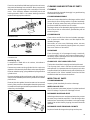
DESCRIPTION
Tu-Flo
®
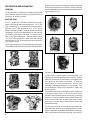
Type 400, 500, and 1000 compressors are single
stage, reciprocating piston type compressors. Tu-Flo
®
400
(Fig. 1) and 500 (Fig. 2) compressors have two cylinders
while the Tu-Flo
®
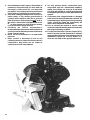
1000 compressor (Fig. 3) is a V-type
design having four cylinders. The rated capacity of all Bendix
compressors is their piston displacement in cubic feet per
minute when operating at 1,250 RPM. The rated capacity
of the Tu-Flo
®
400 compressor is 7-1/4 cubic feet per minute.
The Tu-Flo
®
500 compressor is rated at 12 cubic feet per
minute and the Tu-Flo
®
1000 compressor has a rating of 24
cubic feet per minute.
Tu-Flo
®
type compressors have automatic type inlet valves.
Their unloading mechanisms are located in the cylinder block
and they have no external moving parts. Both air and water
cooled type compressors are available. Various mounting
and drive adaptations are used as required by different vehicle
engine designs (Fig. 4).
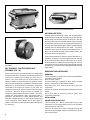
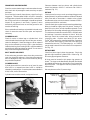
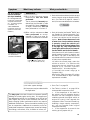
Compressors are either engine or self-lubricated. The
majority used are the engine lubricated types (Fig. 5) which
obtain the oil necessary to lubricate their moving parts from
the engines on which they are mounted. To meet the
requirements of some manufacturers and for field
installations, self-lubricated types (Fig. 6) are available. They
are compressors having a self-contained oil supply and
pumping system.
The method of lubricating the moving parts of the compressor
is the same in either type. Oil is forced through the oil
passage in the crankshaft and out around each connecting
rod journal. The turning motion of the crankshaft throws the
oil that is forced out at the journals, against the cylinder
bores and crankcase walls, lubricating the bores and
crankshaft bearings.
The wrist pins and wrist pin bushings are lubricated in two
ways depending upon the type connecting rods used. Older
design compressors had forged steel rifle-drilled rods through
which oil was forced to the wrist pin bushings. Later versions
FIGURE 2 - TU-FLO
®
500 AIR COMPRESSOR
FIGURE 3 - TU-FLO
®
1000 AIR COMPRESSOR
FIGURE 1 - TU-FLO
®
400 AIR COMPRESSOR
FIGURE 4 - VARIOUS COMPRESSOR MOUNTINGS

3
had either die cast aluminum, cast ductile iron, or forged
steel rods which were not rifle drilled but were drilled at the
top of the rod. The wrist pins and bushings are lubricated
by oil dripping from a drip-boss on the piston into a
“catch-funnel” at the top of the rod and through the drilled
passage to the bushings and pins. (SEE FIG. 7)
A nameplate is attached to the crankcase of all compressors.
It shows the piece number, type and serial number (Fig. 8).
A nameplate with a black background denotes a new
compressor, whereas a nameplate with a red background
designates that the compressor is a factory reconditioned
unit. All compressors are identified by the piece number
which is the number to use when reference is made to a
particular compressor. The type and serial number is
supplementary information.
OPERATION
GENERAL
All compressors run continuously while the engine is running,
but actual compression of air is controlled by a governor,
which stops or starts the compression of air by loading or
unloading the compressor in conjunction with its unloading
mechanism. This is done when the air pressure in the system
reaches the desired maximum or minimum pressures.
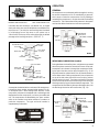
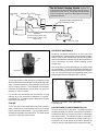
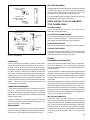
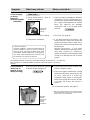
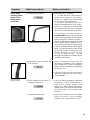
INTAKE AND COMPRESSION (Loaded)
During the down stroke of the piston, a slight vacuum created
above the piston causes the inlet valve to move off its seat.
Atmospheric air is drawn in through the compressor intake,
by the open inlet valve, and on top of the piston (Fig. 9). As
the piston starts its upward stroke, the air that was drawn in
on the down stroke is being compressed. Now, air pressure
on top of the inlet valve plus the force of its spring, returns
the inlet valve to its seat. The piston continues the upward
stroke and compresses the air sufficiently to overcome the
discharge valve spring and unseat the discharge valve. The
compressed air then flows by the open discharge valve, into
the discharge line and on to the reservoirs (Fig. 10).
FIGURE 5
ENGINE LUBRICATED TYPE
FIGURE 6
SELF-LUBRICATED TYPE
FIGURE 9
FIGURE 10
DISCHARGE
VALVE
PISTON
STROKE
TO GOVERNOR
INTAKE
STRAINER
UNLOADER PLUNGER
INLET VALVE
TO RESERVOIR
INTAKE
DISCHARGE
VALVE
PISTON
STROKE
TO GOVERNOR
INTAKE
STRAINER
UNLOADER PLUNGER
INLET VALVE
TO RESERVOIR
COMPRESSION
FIGURE 8 - COMPRESSOR NAMEPLATE
FIGURE 7- PISTONS & CONNECTING RODS
NEW DESIGN
WRIST PIN
BUSHING
“CATCH FUNNEL”
DIE CAST
PISTON
DIE CAST
CONNECTING ROD
OLD DESIGN
OIL
PASSAGE
WRIST PIN
WRIST PIN
BUSHING
PISTON WRIST PIN
LOCK WIRE
CAST IRON
PISTON
STEEL
CONNECTING
ROD

4
As the piston reaches the top of its stroke and starts down,
the discharge valve spring returns the discharge valve to its
seat. This prevents the compressed air in the discharge
line from returning to the cylinder bore as the intake and
compression cycle is repeated.
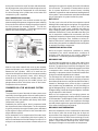
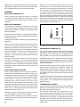
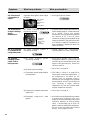
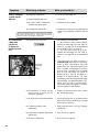
NON-COMPRESSION (Unloaded)
When the air pressure in the reservoir reaches the high
pressure setting of the governor, the governor opens, allowing
air to pass from the reservoir through the governor and into
the cavity beneath the unloader pistons. This lifts the
unloader pistons and plungers. The plungers move up and
hold the inlet valves off their seats (Fig. 11).
With the inlet valves held off their seats by the unloader
pistons and plungers, air is merely pumped back and forth
between the two cylinders. When air is used from the
reservoir and the pressure drops to the low pressure setting
of the governor, the governor closes, and in doing so,
exhausts the air from beneath the unloader pistons. The
unloader saddle spring forces the saddle, pistons and
plungers down and the inlet valves return to their seats.
Compression is then resumed.
COMPRESSOR & THE AIR BRAKE SYSTEM
GENERAL
The compressor is part of the total air brake system, more
specifically, the charging portion of the air brake system. As
a component in the overall system its condition, duty cycle,
proper installation and operation will directly affect other
components in the system.
Powered by the vehicle engine, the air compressor builds
the air pressure for the air brake system. The air compressor
is typically cooled by the engine coolant system, lubricated
by the engine oil supply and has its inlet connected to the
engine induction system.
As the atmospheric air is compressed, all the water vapor
originally in the air is carried along into the air system, as
well as a small amount of the lubricating oil as vapor. If an
air dryer is not used to remove these contaminants prior to
entering the air system, the majority, but not all, will condense
in the reservoirs. The quantity of contaminants that reach
the air system depends on several factors including
installation, maintenance and contaminant handling devices
in the system. These contaminants must either be eliminated
prior to entering the air system or after they enter.
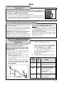
DUTY CYCLE
The duty cycle is the ratio of time the compressor spends
building air to the total engine running time. Air compressors
are designed to build air (run "loaded") up to 25% of the
time. Higher duty cycles cause conditions that affect air
brake charging system performance which may require
additional maintenance. Factors that add to the duty cycle
are: air suspension, additional air accessories, use of an
undersized compressor, frequent stops, excessive leakage
from fittings, connections, lines, chambers or valves, etc.
Refer to Table A in the Troubleshooting section for a guide to
various duty cycles and the consideration that must be given
to maintenance of other components.
COMPRESSOR INSTALLATION
While the original compressor installation is usually
completed by the vehicle manufacturer, conditions of
operation and maintenance may require additional
consideration. The following presents base guidelines.
DISCHARGE LINE
The discharge line allows the air, water-vapor and oil-vapor
mixture to cool between the compressor and air dryer or
reservoir. The typical size of a vehicle's discharge line, (see
column 2 of Table A in the Troubleshooting section) assumes
a compressor with a normal (less than 25%) duty cycle,
operating in a temperate climate. See Bendix and/or other
air dryer manufacturer guidelines as needed.
The discharge line must maintain a constant slope down
from the compressor to the air dryer inlet fitting or reservoir
to avoid low points where ice may form and block the flow. If,
instead, ice blockages occur at the air dryer or reservoir
inlet, insulation may be added here, or if the inlet fitting is a
typical 90 degree fitting, it may be changed to a straight or
45 degree fitting. Shorter discharge line lengths or insulation
may be required in cold climates.
While not all compressors and charging systems are
equipped with a discharge line safety valve this component
is recommended. The discharge line safety valve is installed
in the cylinder head or close to the compressor discharge
port and protects against over pressurizing the compressor
in the event of a discharge line freezeup.
DISCHARGE LINE TEMPERATURE
When the temperature of the compressed air that enters
the air dryer is within the normal range, the air dryer can
remove most of the charging system oil. If the temperature
of the compressed air is above the normal range, oil as oil-
vapor is able to pass through the air dryer and into the air
system. Larger diameter discharge lines and/or longer
discharge line lengths can help reduce the temperature.
FIGURE 11
DISCHARGE
VALVE
PISTON
STROKE
TO GOVERNOR
INTAKE
STRAINER
UNLOADER
PLUNGER
INLET VALVE
TO RESERVOIR
UNLOADING

5
PREVENTIVE MAINTENANCE
Regularly scheduled maintenance is the single most
important factor in maintaining the air brake charging system.
Refer to Table A in the Troubleshooting section for a guide to
various considerations that must be given to the maintenance
of the compressor and other related charging system
components.
If the compressor is a self-lubricated type, its oil level should
be checked daily. The oil level should be kept between the
bottom of the dipstick threads and the bottom of the dipstick
(Fig. 13). Every 8,000 miles or 300 operating hours, the oil
should be drained and refilled with SAE 10-20-30.
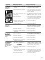
FIGURE 12A - SYSTEM DRAWING
Air Dryer
Reservoir Drain
Service Reservoir
(Supply Reservoir)
Compressor
Governor
(Governor plus Synchro valve
for the Bendix
®
DuraFlo
™
596
Compressor)
Discharge
Line
Optional “Ping” Tank
Optional Bendix
®
PuraGuard
®
QC
™
Oil Coalescing Filter
The Air Brake Charging System supplies the
compressed air for the braking system as well as other air
accessories for the vehicle. The system usually consists
of an air compressor, governor, discharge line, air dryer,
and service reservoir.
FIGURE 12B - DISCHARGE LINE SAFETY VALVE
HOLE
THREAD
The air dryer contains a filter that collects oil droplets, and a
desiccant bed that removes almost all of the remaining water
vapor. The compressed air is then passed to the air brake
service (supply) reservoir. The oil droplets and the water
collected are automatically purged when the governor
reaches its "cut-out" setting.
For vehicles with accessories that are sensitive to small
amounts of oil, we recommend installation of a Bendix
®
PuraGuard
®
QC
™
oil coalescing filter, designed to minimize
the amount of oil present.
COOLING
Tu-Flo
®
400, 500 or 1000 compressors may be air-cooled or
water- cooled and in some instances will have air-cooled
blocks and water-cooled heads. The air-cooled versions
are easily recognized by the external fins. The water-cooled
versions are cooled by vehicle coolant.
FIGURE 13 - OIL LEVEL - SELF-LUBRICATED
COMPRESSOR
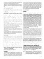
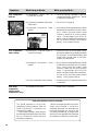
POLYURETHANE SPONGE STRAINER (Fig. 14)
Remove and wash all of the parts. The strainer element
should be cleaned or replaced. If the element is cleaned, it
should be washed in a commercial solvent or a detergent
and water solution. The element should be saturated in
clean engine oil, then squeezed dry before replacing it in
the strainer. Be sure to replace the air strainer gasket if the
entire air strainer is removed from the compressor intake.

6
FIGURE 14 - POLYURETHANE SPONGE STRAINER
FIGURE 15 - DRY ELEMENT- PLEATED PAPER AIR
STRAINER
FIGURE 16 - COMPRESSOR INTAKE ADAPTER
DRY ELEMENT - PLEATED PAPER AIR
STRAINER (FIG. 15)
Remove the spring clips from either side of mounting baffle
and remove the cover. Replace the pleated paper filter and
remount the cleaned cover making sure the filter is in
position. Be sure to replace the air strainer gasket if the
entire air strainer is removed from the compressor intake.
(NOTE: Some compressors are fitted with compressor intake
adapters (Fig. 16) which allow the compressor intake to be
connected to the engine air cleaner.) In this case, the
compressor receives a supply of clean air from the engine
air cleaner. When the engine air filter is changed, the
compressor intake adapter should be checked. If it is loose,
remove the intake adapter, clean the strainer plate, if
applicable, and replace the intake adapter gasket, and
reinstall the adapter securely. Check line connections both
at the compressor intake adapter and at the engine air
cleaner. Inspect the connecting line for ruptures and replace
it if necessary.
AIR LEAKAGE TESTS
Leakage past the discharge valves can be detected by
removing the discharge line, applying shop air back through
the discharge port and listening for escaping air. Also the
discharge valves and the unloader pistons can be checked
for leakage by building up the air system until the governor
cuts out, then stopping the engine. With the engine stopped,
carefully listen for escaping air at the intake. To pinpoint
leakage if noted, squirt oil around the unloader pistons. If
there is no noticeable leakage at the unloader pistons, the
discharge valves may be leaking.
If the compressor does not function as described above, or
leakage is excessive, it is recommended that it be returned
to the nearest Bendix authorized distributor for a factory
rebuilt compressor under the repair exchange plan. If this is
not possible, the compressor can be repaired with genuine
Bendix parts, in which case the following information should
prove helpful.
REMOVING AND INSTALLING
REMOVING
These instructions are general and in some cases additional
precautions must be taken.
Drain air brake system.
If water-cooled type compressor, drain engine cooling
system, compressor cylinder head and block.
Disconnect all air lines, water and oil lines to and from
compressor.
Remove compressor mounting bolts and compressor from
engine.
Use a gear-puller to remove the gear or pulley from
compressor crankshaft.
INSTALLATION
ENGINE-LUBRICATED TYPES
Clean oil supply line. Before connecting this line to the
compressor, run the engine briefly to be sure oil is flowing
freely through the supply line.
Clean the oil return line or return passages through the
brackets; these passages must be unrestricted so oil can
return to the engine.

7
Prelubricate compressor cylinder walls and bearings with
clean engine oil before assembling compressor.
Always use a new mounting gasket and be sure oil hole in
gasket and compressor is properly aligned with oil supply
line.
SELF-LUBRICATED TYPES
Fill compressor crankcase with clean engine oil before
operating compressor. Refer to “Tabulated Data” section for
proper amount.
ALL TYPES
Inspect pulley or gear and associated parts for wear or
damage. They must be a neat fit on compressor crankshaft.
Replace pulley or gear if worn or damaged.
Install pulley or gear on compressor crankshaft making sure
it properly contacts the shaft and does not ride the key.
Tighten crankshaft nut to 65-70 ft. lbs. and install cotter
pin.
Be sure the air cleaner is clean and properly installed. If the
compressor intake is connected to either the engine air
cleaner or supercharger, these connections must be tight
with no leakage.
Clean or replace any damaged or dirty air or water lines
which may be corroded, before connecting them to the
compressor. Use a new discharge fitting gasket.
Align compressor drive and adjust proper belt tension.
Tighten mounting bolts securely and evenly.
After installation, run compressor and check for air, oil, or
water leaks at compressor connections. Also check for
noisy operation.
Check the exterior of the compressor for the presence of oil
seepage and refer to the TROUBLESHOOTING section for
appropriate tests and corrective action.
OIL PASSING
All reciprocating compressors currently manufactured will
pass a minimal amount of oil. Air dryers will remove the
majority of oil prior to entrance into the air brake system.
For particularly oil sensitive systems the Bendix
®
PuraGuard
®
QC
™
oil coalescing filter can be used in conjunction with a
Bendix air dryer.
If compressor oil passing is suspected, refer to the
TROUBLESHOOTING section and TABLE A for the
symptoms and corrective action to be taken. In addition,
Bendix has developed the "Bendix Air System Inspection
Cup" or BASIC test to help substantiate suspected excessive
oil passing. The steps to be followed when using the BASIC
test are presented in APPENDIX A at the end of the
TROUBLESHOOTING section.
REMOVING AND DISASSEMBLY
REMOVING
These instructions are general and are intended to be a
guide. In some cases additional preparations and
precautions are necessary. Chock the wheels of the vehicle
and drain the air pressure from all the reservoirs in the system.
Drain the engine cooling system and the cylinder head of
the compressor. Disconnect all air, water and oil lines leading
to and from the compressor. Remove the drive gear(s) or
pulley from the compressor crankshaft using a gear puller.
Inspect the pulley or gear and associated parts for visible
wear or damage. Since these parts are precision fitted,
they must be replaced if they are worn or damaged.
DISASSEMBLY
GENERAL
Remove road dirt and grease from the exterior of the
compressor with a cleaning solvent. Before the compressor
is disassembled, the following items should be marked to
show their relationship when the compressor is assembled.
Mark both the front and rear end cover in relation to the
crankcase. Mark the drive end of the crankshaft in relation
to the front end cover and the crankcase. Mark the cylinder
head in relation to the block and block to crankcase. Mark
the base plate or base adapter in relation to the crankcase.
A convenient method to indicate the above relationships is
to use a metal scribe to mark the parts with numbers or
lines. Do not use a marking method that can be wiped off or
obliterated during rebuilding, such as chalk. Remove all
compressor attachments such as governors, air strainers
or inlet fittings, discharge fittings and pipe plugs.
CYLINDER HEAD
Remove the cylinder head cap screws and tap the head
with a soft mallet to break the gasket seal. Remove the
inlet valve springs form the head and inlet valves from their
guides in the block. Remove inlet valve guides from around
the inlet valve seats on the block, taking care not to damage
seats. Scrape off any gasket material from the cylinder
head and block. Unscrew the discharge cap nuts from the
head and remove the discharge valves and springs. Inspect
the discharge valve seats for nicks, cracks, and excessive
wear and remove and replace if necessary.
The discharge valve cap nuts should be inspected for wear
and replaced if excessive peening has occurred. To
determine if excessive peening has occurred, measure the
discharge valve travel. Discharge valve travel must not exceed
.056 in. for the Tu-Flo
®
400 compressor and .046 in. for the
Tu-Flo
®
500 and 1000 compressors.
CRANKCASE BASE PLATE OR ADAPTER
Remove the cap screws securing the base plate or base
adapter. Tap with soft mallet to break the gasket seal. Scrape
off any gasket material from crankcase and plate or adapter.
CONNECTING ROD ASSEMBLIES
(NOTE: Before removing the connecting rods, mark each
connecting rod and its cap. Each connecting rod
is matched to its own cap for proper bearing fit, and
these parts must not be interchanged.)

8
Straighten the prongs of the connecting rod bolt lock strap
and remove the bolts and bearing caps. Push the piston
with the connecting rods attached out the top of the cylinders
of the crankcase. Replace the bearing caps on their
respective connecting rods. Remove the piston rings from
the pistons. If the pistons are to be removed from the
connecting rods, remove the wrist pin lock wires or teflon
plugs and press the wrist pins from the pistons and
connecting rods.
If the pistons are removed from the rod, inspect the bronze
wrist pin bushing. Press out and replace the bushing if it is
excessively worn. (See Inspection of Parts.) Discard the
piston rings and the connecting rod journal bearings. Discard
the wrist pin bushings if they were removed. New Tu-Flo
®
400 compressors manufactured after approximately
September 1977 will have connecting rods without bearing
inserts. Repair size rods will have inserts.
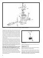
REMOVING AND DISASSEMBLING BASE PLATE
SELF-LUBRICATED TYPE COMPRESSORS (Fig. 18)
Remove screws that hold base plate. Remove base plate.
Remove oil relief valve set screw, then oil relief valve.
Remove oil strainer retaining ring and lift out oil strainer.
Unless it is necessary, the oil pump piston bushing should
not be removed. If necessary, remove the bushing set screw,
then bushing and shim.
Remove cotter pin from oil rod cap nuts, remove nuts, oil
pump piston rod and cap.
CRANKCASE (Fig. 19)
Remove end cover with oil seal, remove end cover gasket.
Replace oil seal after cleaning end cover.
Remove cap screws that hold opposite end cover to
crankcase; remove end cover and its gasket. Some
compressors have crankcases that have a shoulder for
positioning the crankshaft. In these cases the crankshaft
must be removed through one particular end.
FIGURE 17 - TU-FLO
®
400 AIR COMPRESSOR VERTICAL MOUNT - ENGINE LUBRICATED
FIGURE 18 - BASE PLATE SELF-LUBRICATED TYPE
COMPRESSOR

9
CLEANING AND INSPECTION OF PARTS
CLEANING
All parts should be cleaned thoroughly in a good cleaning
solvent before inspection.
CYLINDER HEAD ASSEMBLY
Remove all carbon deposits from discharge cavities and all
rust and scale from cooling cavities of cylinder head body.
Scrape all foreign matter from body surfaces and use air
pressure to blow dirt particles from all cavities.
Discharge valves can be dressed by lapping them on a piece
of fine crocus cloth on a flat surface, provided they are not
excessively worn.
CYLINDER BLOCK
Clean carbon and dirt from inlet and unloader passages.
Use air pressure to blow carbon and dirt deposits from
unloader passages.
Inlet valves, as in the case of discharge valves, not worn
excessively, can be cleaned by lapping them on a piece of
fine crocus cloth on a flat surface.
OIL PASSAGE
Clean thoroughly all oil passages through crankshaft,
connecting rods, crankcase, end covers and base plate. If
necessary, inspect passages with a wire and blow foreign
matter out with air pressure.
CRANKCASE - SELF-LUBRICATED TYPE
The breather should be thoroughly washed and cleaned.
The oil pump check valve in the base should be removed
and replaced. It is important when the oil pump check valve
is replaced that it be installed correctly with the ball stop pin
end pressed in first. When installed, the ball and its seat
should be visible from the crankcase base.
INSPECTION OF PARTS
CYLINDER HEAD BODY
Inspect cylinder head body for cracks or damage.
WATER-COO LED TYPE
Use air pressure to test water jackets of cylinder head and
block for leakage. Replace unit if leakage is found.
DISCHARGE VALVES AND SEATS
If discharge valves are worn and grooved where they contact
the seats, they should be replaced. If the discharge valve
seats are worn excessively so that there is no longer enough
metal left to reclaim them by lapping, the seats should be
replaced.
DISCHARGE VALVE SPRING AND CAP NUTS
Replace all used discharge valve springs and cap nuts.
FIGURE 20 - CYLINDER BLOCK - EXPLODED VIEW
Press the crankshaft and ball bearings from the crankcase,
then press ball bearings from crankshaft. Many compressors
will have sleeve-type bearings in the crankcase or in the end
cover. If the clearance between crankshaft journal and
bearing exceeds .0065 in. the sleeve bearing should be
replaced with appropriate undersize.
BLOCK (Fig. 20)
If compressor is fitted with an air strainer, inlet elbow or
governor, remove same.
Remove cap screws securing cylinder block to crankcase;
separate crankcase and cylinder block and scrape off gasket.
Remove unloader spring, spring saddle and spring seat from
cylinder block.
Remove unloader guides and plungers and, with the use of
shop air, blow unloader pistons out of cylinder block unloader
piston bores.
Remove inlet valve guides; inlet valve seats can be removed
but only if they are worn or damaged and are being replaced.
Unloader bore bushings should be inspected but not removed
unless they are damaged.
FIGURE 19 - CRANKCASE - TU-FLO
®
400 & 500 AIR
COMPRESSORS
FIGURE 19A - CRANKCASE - TU-FLO
®
1000 AIR
COMPRESSOR

10
CRANKCASE AND END COVERS
Check for cracks or broken lugs in crankcase and end covers.
Also check their oil passages to make sure they are open
and clean.
If an oil seal ring is used in the end cover, check fit of ring in
ring groove. There should be 0.008 in. to 0.015 in. clearance
at the gap when placed in the end bore of the crankshaft. If
the oil ring is worn thin or is damaged, it should be replaced.
Inspect oil ring groove in end cover; if groove is worn
excessively replace end cover or machine groove for next
oversize oil seal ring.
If the crankshaft main bearings are installed in the end cover,
check for excessive wear and flat spots and replace if
necessary.
CYLINDER BLOCK
Check for cracks or broken lugs on cylinder block. Also
check unloader bore bushings to be sure they are not worn,
rusted or damaged. If these bushings are to be replaced
they can be removed by running a 1/8 in. pipe thread tap
inside the bushing, then inserting a 1/8 in. pipe threaded rod
and pulling the bushing straight up and out. Do not use an
easy-out for removing these bushings.
INLET VALVES AND SEATS
If inlet valves are grooved or worn where they contact the
seat, they should be replaced. If the inlet valve seats are
worn or damaged so they cannot be reclaimed by facing,
they should be replaced.
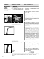
CYLINDER BORES
Cylinder bores which are scored or out of round by more
than 0.002 in. or tapered more than 0.003 in. should be
rebored or honed oversize. Oversize pistons are available in
0.010, 0.020, and 0.030 oversizes.
Cylinder bores must be smooth, straight and round.
Clearance between cast iron pistons and cylinder bores
should be between 0.002 in. minimum and 0.004 in.
maximum (Fig. 21).
PISTONS
Check pistons for scores, cracks or enlarged ring grooves;
replace pistons if any of these conditions are found. Measure
each piston with a micrometer in relation to the cylinder
bore diameter to be sure the clearance is between 0.002 in.
minimum and 0.004 in. maximum.
Check fit of wrist pins on pistons and connecting rod bushings.
Wrist pin should be a light press fit in pistons. If wrist pin is
loose fit, the pin, piston, or both should be replaced. Check
fit of wrist pin in connecting rod bushing by rocking the piston.
This clearance should not exceed 0.0015 in. Replace wrist
pin bushings if excessive clearance is found. Wrist pin
bushings should be reamed after being pressed into
connecting rods. Replace used wrist pin lock wires.
Tu-Flo
®
400 compressors manufactured after September
1977 will have Teflon plugs in each end of the wrist pins
instead of the lock wire. The Teflon plugs (pc. no. 292392)
may be used instead of the lock wires on all compressors.
See Fig. 22.
PISTON RINGS
Check fit of piston rings in piston ring grooves. Check ring
gap with rings installed in cylinder bores. Refer to Fig. 24
for correct gap and groove clearance.
All rings must be located in their proper ring grooves as
shown. The rings can be identified by the width and should
be installed with the bevel or the pipmark (if any) toward the
top of the piston. This applies to cast iron pistons (only as
shown above).
Die cast pistons use five (5) narrow rings.
FIGURE 21 - MEASURING CYLINDER BORES
FIGURE 22 - TU-FLO
®
400 AIR COMPRESSOR NEW STYLE
COMPRESSION
RINGS (2)
COMPRESSION
RINGS (2)

11
CRANKSHAFT
Check crankshaft screw threads, keyways, tapered ends
and all machined and ground surfaces for wear, scores, or
damage. Crankshaft journals which are out of round more
than 0.001 in. must be reground. Bearing inserts are available
in 0.010 in., 0.020 in., and 0.030 in. undersizes for reground
crankshafts. Main bearing journals must be maintained so
bearings are snug fit. The oil seal ring groove or grooves in
crankshafts fitted with oil seal rings must not be worn. The
ring groove walls must have a good finish and they must be
square. Check to be sure the oil passages are open and
clean through the crankshaft.
CONNECTING ROD BEARINGS
Check connecting rod bearings on crankshaft journals for
proper fit. Used bearing inserts should be replaced.
Connecting rod caps are not interchangeable. The locking
slots of the connecting rod and cap should be positioned
adjacent to each other.
Clearance between the connecting rod journal and the
connecting rod bearing must not be less than 0.0003 in. or
more than 0.0021 in. after rebuilding.
MAIN BEARINGS
Check for wear or flat spots; if found, bearings should be
replaced. If type with sleeve bearing, this bearing should be
checked for scores and wear and replaced if necessary.
UNLOADER MECHANISM
Used unloader mechanism should be replaced by unloader
kits 265014 for Type Tu-Flo
®
400 compressors and 265015
for Types Tu-Flo
®
500 and 1000 compressors. The Tu-Flo
®
1000 compressor requires two kits per compressor.
The new unloader pistons should be a loose sliding fit in the
unloader piston bores of the cylinder block.
PARTS SPECIAL TO SELF-LUBRICATED
TYPE COMPRESSORS
OIL PUMP SCREEN
Check oil pump screen to be sure it is clean and not
damaged; replace if damaged.
OIL PUMP PISTON AND BUSHING
Check fit of oil pump piston in base plate pump bushing. It
must be a medium sliding fit. If excessive clearance is
found, the oil rod and/or bushing must be replaced.
OIL PUMP RELIEF VALVE
If the oil pump relief valve is defective, it should be replaced.
OIL PUMP CHECK VALVE
The check valve should be replaced. It can be checked by
applying air pressure back through the pin stop end and
noting that the ball check seals on its seat.
REPAIRS
DISCHARGE VALVES AND SEATS
If discharge valve seats merely show signs of slight wear,
they can be dressed by using a lapping stone, grinding
compound and grinding tool. Install new discharge valves
and valve springs.
To test for leakage by the discharge valves, apply about 100
pounds of air pressure through the cylinder head discharge
port and apply soap suds at the discharge valves and seats.
Leakage which will permit the formation of bubbles is
permissible.
If excessive leakage is found, leave the air pressure applied,
and with the use of a fibre or hardwood dowel and hammer,
tap the discharge valves off their seats several times. This
will help the valves to seat and should reduce any leakage.
With the air pressure still applied at the discharge port of
the cylinder head, check for leakage at the discharge valve
cap nuts. No leakage is permissible.
INLET VALVES AND SEATS
If inlet valve seats show sign of slight nicks or scratches,
they can be redressed with a fine piece of emery cloth or by
lapping with a lapping stone, grinding compound and grinding
tool. If the seats are excessively damaged to the extent
that they cannot be reclaimed, they should be replaced.
The dimension from the top of the cylinder block to the inlet
valve seat should not exceed 0.118 in. nor be less than
0.101 in.
FIGURE 23 - TU-FLO
®
400 AIR COMPRESSOR OLD STYLE
TU-FLO
®
400 AIR COMPRESSOR
CORRECT GROOVE
CLEARANCE
.0015”
.0030”
CORRECT GAP
CLEARANCE WITH RING
IN CYLINDER
.0035”
.014”
FIGURE 24 - PISTON RING POSITIONS - GAPS AND
GROOVE CLEARANCE
TU-FLO
®
500 & 1000 AIR COMPRESSOR
CORRECT GROOVE
CLEARANCE
.0035”
.0035”
CORRECT GAP
CLEARANCE WITH RING
IN CYLINDER
.0035”
.014”
.002”
.004”
WIDE
NARROW
WIDE
NARROW

12
Slightly worn or scratched inlet valves can be reclaimed by
lapping them on a piece of fine crocus cloth on a flat surface,
but it is suggested that new inlet valves be installed.
ASSEMBLY
INSTALLING CYLINDER BLOCK
Position cylinder block gasket and block on crankcase
according to markings made prior to disassembly. Using
cap screws with lock washers, secure cylinder block to
crankcase.
INSTALLING CRANKSHAFT
If the crankshaft is fitted with oil seal rings, install rings.
Position ball bearings and crankshaft in crankcase, making
sure the drive end of the crankshaft is positioned as marked
before disassembly.
If one end of the crankcase is counterbored for holding a
bearing, be sure the crankshaft is installed through the correct
end of the crankcase.
Carefully press crankshaft and bearings into crankcase using
arbor press.
Position a new rear end cover gasket, when used, over the
rear end of the crankcase, making sure the oil hole in the
gasket lines up with the oil hole in the crankcase. Position
end cover with oil seal ring, if used, installed over crankcase
and end cover gasket. The end cover should be positioned
correctly in relation to the oil holes in the gasket and
crankcase. Secure end cover to crankcase with cap screws
and lock washers.
If the opposite end cover requires an oil seal which was
removed on disassembly, a new seal should be pressed
into end cover. Position new end cover gasket and carefully
install end cover over crankshaft and to crankcase, avoiding
damage to the seal. Secure end cover with cap screw and
lock washers.
PISTONS AND CONNECTING RODS
If new wrist pin bushings are to be used, they should be
pressed into the connecting rods so that the oil hole in the
bushing lines up with the one in the rod. The new bushings
should then be reamed or honed to provide between 0.0002
in and 0.0007 in. clearance on the wrist pin. Position
connecting rod in piston and press in wrist pin so that
lockwire hole in the pin aligns with that of the piston. Install
new lockwire through piston and wrist pin and lock same by
snapping short end into lockwire hole at the bottom of the
piston (Fig. 7). Teflon plugs in wrist pin ends may be used
instead of the lockwires (Fig. 22).
Install piston rings in correct location with ring pipmarks up
(Fig. 24). Stagger the position of the ring gaps.
Prelubricate piston, piston rings, wrist pin and connecting
rod bearings with clean engine oil before installing them in
the compressor.
Remove connecting bolts and bearing cap from one
connecting rod. Turn crankshaft so one of its connecting
rod journals is in the downward, center position. Compress
the rings with a ring compression tool and insert the
connecting rod with piston through the top of the cylinder
whose journal is down. Position and attach the bearing cap
to the connecting rod, making sure the bolt lock washers
are properly positioned on the cap. Tighten connecting rod
bolts evenly and bend the two new lock washer prongs up
against the hex head of the bolt. Install the other connecting
rod and piston in the same manner.
FIGURE 25 - UNLOADER MECHANISM
UNLOADER MECHANISM (Fig. 25)
The unloader pistons and their bores must be lubricated
with special lubricant piece number 239379 (dimethyl
polysiloxane) prior to installation. If new unloader kits are
being installed, the pistons in the kit are already lubricated.
Install the unloader pistons in their bores with caution against
cutting the grommets or distorting the back-up rings. Position
unloader plungers in their guides and slip them in and over
the tops of the pistons.
Install the unloader spring seat in the cylinder block; a small
hole is drilled in the block for this purpose. Position the
saddle between unloader piston guides so its forks are
centered on the guides. Install the unloader spring, making
sure it seats over the spring seats both in the block and on
the saddle.
Install inlet valve seats if they have been previously removed.
Position and install inlet valve guides, then drop inlet valves
in their guides. There should be a loose sliding fit between
guides and valves.
CYLINDER HEAD ASSEMBLY
If previously removed, the discharge valve seats should be
installed. Drop discharge valves into their seats. Install
discharge valve springs and cap nuts.
Place the inlet valve springs in the cylinder head. Use a
small quantity of grease to hold them in place, just enough
grease to keep the springs from falling out. Place cylinder
head gasket on cylinder block. Carefully align cylinder head
assembly on block and install cap screws with lock washers.
Tighten securely and evenly cap screws that hold cylinder
head to block.

13
BASEPLATE
SELF-LUBRICATED TYPE COMPRESSORS
Install oil pump piston and rod on crankshaft.
Oil rod bearing fit must be the same as specified for
connecting rod bearings. Install oil rod cap nuts and cotter
pins to lock oil rod nuts.
Install oil pump relief valve in base plate. The relief valve can
be tested at this stage by applying air pressure to the relief
valve. The valve should open when the pressure is between
14 psi minimum and 24 psi maximum. When the relief valve
is properly installed in the base plate, install set screw that
locks it in place.
Place oil pump screen in base and install retaining ring,
making sure it snaps in place and secures the screw.
Install oil filter fitting on base plate in its proper place. Install
blanking cover on opposite oil filter fitting hole in plate.
Install a new oil seal gasket around oil pump - check valve
and position a new base plate gasket on the crankcase.
Position base plate assembly on crankcase, making sure
oil pump piston engages the oil pump bushing in the base
plate. Install and tighten base plate screws.
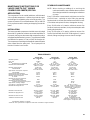
TESTING REBUILT COMPRESSOR
In order to properly test a compressor under operating
conditions, a test rack for correct mounting, cooling,
lubricating and driving the compressor is necessary. Such
tests are not compulsory if the unit has been carefully rebuilt
by an experienced person.
A compressor efficiency or build-up test can be run which is
not too difficult. Before the test, the crankcase of a self-
lubricated type compressor should be properly filled with
lubricating oil. An engine lubricated compressor must be
connected to an oil supply line of at least 15 pounds pressure
during the test and an oil return line must be installed to
keep the crankcase drained. The compressor (when tested)
should be tested without a strainer.
To the discharge port of the compressor, connect a reservoir
or reservoirs whose volume plus the volume of the connecting
line equals 1,300 cubic inches. Run the compressor between
1,700 and 1,750 RPM. Elapsed time that the compressor
takes to build up from 0 to 100 psi depends on the type
compressor as follows:
BUILD-UP TIME
TYPE COMPRESSOR 0 TO 100 PSI
TU-FLO
®
400 47 SECONDS MAXIMUM
TU-FLO
®
500 30 SECONDS MAXIMUM
TU-FLO
®
1000 15 SECONDS MAXIMUM
During the above test the compressor should be checked
for oil leakage and noisy operation.
COMPRESSOR TROUBLESHOOTING
IMPORTANT: The troubleshooting contained in this section
considers the compressor as an integrated component of
the overall air brake charging system and assumes that an
air dryer is in use. The troubleshooting presented will cover
not only the compressor itself, but also other charging system
devices as they relate to the compressor.
WARNING! PLEASE READ AND FOLLOW
THESE INSTRUCTIONS TO AVOID
PERSONAL INJURY OR DEATH:
When working on or around a vehicle, the following
general precautions should be observed at all times.
1. Park the vehicle on a level surface, apply the
parking brakes, and always block the wheels.
Always wear safety glasses.
2. Stop the engine and remove ignition key when
working under or around the vehicle. When
working in the engine compartment, the engine
should be shut off and the ignition key should be
removed. Where circumstances require that the
engine be in operation, EXTREME CAUTION should
be used to prevent personal injury resulting from
contact with moving, rotating, leaking, heated or
electrically charged components.
FIGURE 26 - AIR STRAINER - EXPLODED VIEW
AIR STRAINER
If the compressor is type with air strainer, assemble strainer
(Fig. 26). Using a new strainer gasket, install strainer on
cylinder block.
GOVERNOR
If compressor is type with pad mounted governor, install a
new or factory rebuilt governor using a new governor gasket.
INSPECTION OF REBUILT UNIT
Check to be sure that covers, plugs or masking tape are
used to protect all ports if compressor is not to be installed
immediately.
Fit the end of all crankshafts with keys, nuts and cotter pins
as required and then protect the ends against damage by
wrapping with masking or friction tape.
The open bottom of engine lubricated compressors should
be protected against the entrance of dirt during handling or
storage, by installing a temporary cover over base.

14
3. Do not attempt to install, remove, disassemble or
assemble a component until you have read and
thoroughly understand the recommended
procedures. Use only the proper tools and observe
all precautions pertaining to use of those tools.
4. If the work is being performed on the vehicle’s air
brake system, or any auxiliary pressurized air
systems, make certain to drain the air pressure
from all reservoirs before beginning ANY work on
the vehicle. If the vehicle is equipped with an AD-
IS
™
air dryer system or a dryer reservoir module,
be sure to drain the purge reservoir.
5. Following the vehicle manufacturer’s
recommended procedures, deactivate the electrical
system in a manner that safely removes all electrical
power from the vehicle.
6. Never exceed manufacturer’s recommended
pressures.
7. Never connect or disconnect a hose or line
containing pressure; it may whip. Never remove a
component or plug unless you are certain all
system pressure has been depleted.
8. Use only genuine Bendix
®
replacement parts,
components and kits. Replacement hardware,
tubing, hose, fittings, etc. must be of equivalent
size, type and strength as original equipment and
be designed specifically for such applications and
systems.
9. Components with stripped threads or damaged
parts should be replaced rather than repaired. Do
not attempt repairs requiring machining or welding
unless specifically stated and approved by the
vehicle and component manufacturer.
10. Prior to returning the vehicle to service, make
certain all components and systems are restored to
their proper operating condition.
11. For vehicles with Antilock Traction Control (ATC),
the ATC function must be disabled (ATC indicator
lamp should be ON) prior to performing any vehicle
maintenance where one or more wheels on a
drive axle are lifted off the ground and moving.

15
TABULATED DATA
TU-FLO
®
400 TU-FLO
®
500 TU-FLO
®
1000
Air Compressor Air Compressor Air Compressor
Number Cylinders 2 2 4
Bore Size 2.0625" 2.5" 2.5"
Stroke 1.5" 1.6875" 1.6875"
Displacement at 1,250 RPM 7.25 cu. ft./min. 12 cu. ft./min. 24 cu. ft./min.
Maximum recommended RPM 3,000 water cooled 3,000 water cooled 3,000 water cooled
2,400 air cooled 2,400 air cooled 2,400 air cooled
Minimum coolant flow at 2.5 gal./min. 2.5 gal./min. 2.5 gal./ min.
maximum RPM water cooled water cooled water cooled
250 CFM air flow 250 CFM air flow 250 CFM air flow
Approximate horsepower required
at 1,250 RPM 1.2 H.P. 2.3 H.P. 4.6 H.P.
Maximum inlet air temperature 250° F. 250° F. 250° F.
Maximum discharge air temperature 400° F. 400° F. 400° F.
Minimum pressure required
to unload 60 PSI 60 PSI 60 PSI
Minimum oil pressure required at
engine idling speed 5 PSI 5 PSI 5 PSI
Minimum oil pressure required at
maximum governed engine speed 15 PSI 15 PSI 15 PSI
Approximate average weight 34 lbs. 46 lbs. 75 lbs.
Oil capacity of self-lubricated model .53 qts. .53 qts. .95 qts. to 5 qts.*
Minimum discharge line size 1/2" O.D. tubing 5/8" O.D. tubing 5/8" O.D. tubing or equivalent
or equivalent or equivalent from each head to a common
manifold with 1" tubing from
manifold.
Minimum coolant line size 3/8" O.D. tubing 1/2" O.D. tubing 1/2" O.D. tubing
or equivalent or equivalent or equivalent
Minimum oil supply line size 1/4" O.D. tubing 1/4" O.D. tubing 1/4" O.D. tubing
or equivalent or equivalent or equivalent
Minimum oil return line size 1/2" O.D. tubing 5/8" O.D. tubing 5/8" O.D. tubing
or equivalent or equivalent or equivalent
**Minimum air inlet line size 5/8" I.D. 5/8" I.D. 1" I.D. if equipped with inlet
manifold; or, dual 5/8" I.D. lines
from engine to compressor inlets.
*Part Number dictates oil capacity
**Inlet line sizes specified for compressors with inlet connected to engine manifold.
MAINTENANCE INSTRUCTIONS FOR
LARGE SUMP TU-FLO
®
1000 AIR
COMPRESSOR 288578 (SPECIAL
APPLICATION)
This compressor is an air-cooled, belt driven, self lubricated,
V-four cylinder compressor. It is driven by an electric motor
and cooling air is supplied by a fan on the driven pulley. The
system air pressure is controlled between 135 psi and 150
psi by a pressure switch starting and stopping the electric
motor.
INSTALLATION
The base mounted compressor should be securely bolted
down with 1/2" grade five or better cap screws torqued to 70
ft. pounds, making sure that motor and compressor pulleys
are aligned and belt tension is correct. The crankcase should
be filled with five quarts (4.7 liter) of SAE 20 W engine oil.
The compressor must always be installed to rotate clockwise
when viewed from the pulley end. The oil pump will not
function if rotation is not correct.
SCHEDULED MAINTENANCE
NOTE: When checking or adding oil or servicing the
crankcase breather, care should be taken to prevent
dirt or foreign material from entering the breather or
oil sump.
Every 7,500 miles or seven weeks, whichever occurs first:
Check oil level - replenish to top of filler plug opening.
Replace both air cleaner filter elements and clean covers.
Check belts and replace if broken, damaged or missing.
Every 15,000 miles or 14 weeks, whichever occurs first:
Remove crankcase ventilator, clean ports and replace with
freshly oiled curled hair.
Every 22,500 miles or 21 weeks, whichever occurs first:
Drain oil and refill with fresh SAE 20 W engine oil. Inspect
all bolts, fittings and plugs to ensure that all are tight.

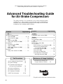
*This guide is only for vehicles that use desiccant air dryers.
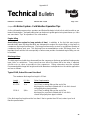
The guide consists of an introduction to air brake charging system
components, a table showing recommended vehicle maintenance
schedules, and a troubleshooting symptom and remedy section with tests
to diagnose most charging system problems.
Advanced Troubleshooting Guide
for Air Brake Compressors
*
This troubleshooting guide obsoletes and supersedes all previous published
troubleshooting information relative to Bendix air compressors.
Air brake charging system:
Slow build (9.0) . . . . . . . . . . . . . . . . . 24 - 25
Doesn’t build air (10.0) . . . . . . . . . . . . . . . 26
Air dryer:
Doesn’t purge (14.0) . . . . . . . . . . . . . . . . . 27
Safety valve releases air (12.0). . . . . . . . . 27
Compressor:
Constantly cycles (15.0) . . . . . . . . . . . . . . 27
Leaks air (16.0) . . . . . . . . . . . . . . . . . . . . . 28
Safety valve releases air (11.0). . . . . . . . . 26
Noisy (18.0) . . . . . . . . . . . . . . . . . . . . . . . . 28
Reservoir:
Safety valve releases air (13.0). . . . . . . . . 27
INDEX
Air
Coolant
Engine
Oil
Compressor leaks coolant (17.0) . . . . . . . . . . 28
Oil consumption (6.0) . . . . . . . . . . . . . . . . . . . 24
Oil Test Card results (1.0) . . . . . . . . . . . . . . . . 19
Oil is present:
On the outside of the compressor (2.0). . . 20
At the air dryer purge/exhaust
or surrounding area (3.0) . . . . . . . . . . . 20
In the supply reservoir (4.0). . . . . . . . 21 - 23
At the valves (5.0) . . . . . . . . . . . . . . . . . . . 23
At air dryer cartridge (7.0) . . . . . . . . . . . . . 24
In the ping tank or compressor
discharge aftercooler (8.0) . . . . . . . . . . 24
Symptom Page Number
(1) Oil Leakage at Head Gasket . . .29
(2) System Leakage . . . . . . . . . . . .29
(3) Compressor Discharge and
Air Dryer Inlet Temperature . . . .29
(4) Governor Malfunction . . . . . . . .30
(5) Governor Control Line . . . . . . . .30
(6) Compressor Unloader . . . . . . . .30
BASIC Test Information . . . . . . 32-34
Test Procedures
Maintenance Schedule and
Usage Guidelines (Table A) . . 18
Symptom Page Number
Maintenance & Usage Guidelines
16

17
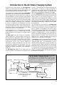
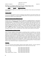
Introduction to the Air Brake Charging System
Powered by the vehicle engine, the air compressor
builds the air pressure for the air brake system. The
air compressor is typically cooled by the engine coolant
system and lubricated by the engine oil supply.
The compressor's unloader mechanism and governor
(along with a synchro valve for the Bendix
®
DuraFlo
™
596
air compressor) control the brake system air
pressure between a preset maximum and minimum
pressure level by monitoring the pressure in the service
(or “supply”) reservoir. When the air pressure becomes
greater than that of the preset “cut-out”, the governor
controls the unloader mechanism of the compressor
to stop the compressor from building air and also
causes the air dryer to purge. As the service reservoir
air pressure drops to the “cut-in” setting of the governor,
the governor returns the compressor back to building
air and the air dryer to air drying mode.
As the atmospheric air is compressed, all the water
vapor originally in the air is carried along into the air
system, as well as a small amount of the lubricating oil
as vapor.
The duty cycle is the ratio of time the compressor
spends building air to the total engine running time.
Air compressors are designed to build air (run “loaded”)
up to 25% of the time. Higher duty cycles cause
conditions that affect air brake charging system
performance which may require additional
maintenance. Factors that add to the duty cycle are:
air suspension, additional air accessories, use of an
undersized compressor, frequent stops, excessive
leakage from fittings, connections, lines, chambers or
valves, etc.
The discharge line allows the air, water-vapor and
oil-vapor mixture to cool between the compressor and
air dryer. The typical size of a vehicle's discharge line,
(see column 2 of Table A on page 18) assumes a
compressor with a normal (less than 25%) duty cycle,
operating in a temperate climate. See Bendix and/or
other air dryer manufacturer guidelines as needed.
When the temperature of the compressed air that enters
the air dryer is within the normal range, the air dryer can
remove most of the charging system oil. If the
temperature of the compressed air is above the normal
range, oil as oil-vapor is able to pass through the air
dryer and into the air system. Larger diameter discharge
lines and/or longer discharge line lengths can help reduce
the temperature.
The discharge line must maintain a constant slope
down from the compressor to the air dryer inlet fitting
to avoid low points where ice may form and block the
flow. If, instead, ice blockages occur at the air dryer
inlet, insulation may be added here, or if the inlet fitting
is a typical 90 degree fitting, it may be changed to a
straight or 45 degree fitting. For more information on
how to help prevent discharge line freeze-ups, see
Bendix Bulletins TCH-08-21 and TCH-08-22 (see
pages 35-37). Shorter discharge line lengths or
insulation may be required in cold climates.
The air dryer contains a filter that collects oil droplets,
and a desiccant bed that removes almost all of the
remaining water vapor. The compressed air is then
passed to the air brake service (supply) reservoir. The
oil droplets and the water collected are automatically
purged when the governor reaches its “cut-out” setting.
For vehicles with accessories that are sensitive to small
amounts of oil, we recommended installation of a
Bendix
®
PuraGuard
®
system filter, designed to minimize
the amount of oil present.
Air Dryer
Reservoir Drain
Service Reservoir
(Supply Reservoir)
Compressor
Governor
(Governor plus Synchro valve
for the Bendix
®
DuraFlo
™
596
™
Compressor)
Discharge
Line
Optional “Ping” Tank
Optional Bendix
®
PuraGuard
®
System Filter or PuraGuard
®
QC
™
Oil Coalescing Filter
The Air Brake Charging System supplies the
compressed air for the braking system as well as other
air accessories for the vehicle. The system usually
consists of an air compressor, governor, discharge line,
air dryer, and service reservoir.

18
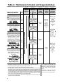
Compressor with up to 25% duty cycle
Footnotes:
1 With increased air demand the air dryer cartridge needs to be replaced more often.
2 Use the drain valves to slowly drain all reservoirs to zero psi.
3 Allow the oil/water mixture to fully settle before measuring oil quantity.
4 To counter above normal temperatures at the air dryer inlet, (and resultant oil-vapor passing
upstream in the air system) replace the discharge line with one of a larger diameter and/
or longer length. This helps reduce the air's temperature. If sufficient cooling occurs, the
oil-vapor condenses and can be removed by the air dryer. Discharge line upgrades are not
covered under warranty. Note: To help prevent discharge line freeze-ups, shorter discharge
line lengths or insulation may be required in cold climates. (See Bendix Bulletins TCH-08-21
and TCH-08-22, included in Appendix B, for more information.)
5 For certain vehicles/applications, where turbo-charged inlet air is used, a smaller size
compressor may be permissible.
Recom- Recom- Acceptable
Typical Discharge mended mended Reservoir
Compressors Line Air Dryer Reservoir Oil Contents
3
No. of Spec'd Cartridge Drain at Regular
Axles Replacement
1
Schedule
2
Drain Interval
High Air Use
Low Air Use
e.g. Double/triple trailer, open
highway coach/RV, (most)
pick-up & delivery, yard or
terminal jockey, off-highway,
construction, loggers, concrete
mixer, dump truck, fire truck.
e.g. Line haul single trailer
w/o air suspension, air over
hydraulic brakes.
e.g. Line haul single trailer
with air suspension,
school bus.
e.g. City transit bus, refuse,
bulk unloaders, low boys,
urban region coach, central
tire inflation.
5
or
less
5
or
less
8
or
less
12
or
less
Table A: Maintenance Schedule and Usage Guidelines
Recom-
mended
Every
Month -
Max of
every 90
days
Every
Month
Every 3
Years
Every 2
Years
Every
Year
I.D.
Vehicle Used for:
Column 1
Column 2 Column 3 Column 4 Column 5
Regularly scheduled maintenance is the single most important factor in maintaining the air brake charging system.
Note: Compressor and/or air dryer
upgrades are recommended in cases
where duty cycle is greater than the
normal range (for the examples
above).
For Bendix
®
Tu-Flo
®
550 and 750
compressors, unloader service is
recommended every 250,000 miles.
Length
6 ft.
1/2 in.
9 ft.1/2 in.
12 ft.
1/2 in.
5/8 in.
12 ft.
BASIC test
acceptable
range:
5 oil units
per month.
See
appendix
A.
For oil carry-over
control
4
suggested
upgrades:
3/4 in. 15 ft.
For oil carry-over
control
4
suggested
upgrades:
5/8 in. 15 ft.
For oil carry-over
control
4
suggested
upgrades:
5/8 in. 9 ft.
For oil carry-over
control
4
suggested
upgrades:
5/8 in. 12 ft.
Compressor with less than 15% duty
cycle
Compressor with up to 25% duty cycle
Compressor with up to 25% duty cycle
Bendix
®
BA-921
™
air compressor
Bendix
®
Tu-Flo
®
550 air compressor
Bendix
®
Tu-Flo
®
750 air compressor
Bendix
®
BA-922
™
, or DuraFlo
™
596
air compressor
BASIC test
acceptable
range:
3 oil units
per month.
See
appendix
A.
For the
BASIC
Test Kit:
Order
Bendix
P/N
5013711

19
ü
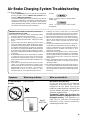
Air Brake Charging System Troubleshooting
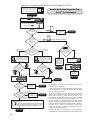
How to use this guide:
1.0 Oil Test Card
Results
Not a valid test.
Discontinue using this test.
Do not use this card test to diagnose
compressor "oil passing" issues. They are
subjective and error prone. Use only the
Bendix Air System Inspection Cup (BASIC) test
and the methods described in this guide for
advanced troubleshooting.
The Bendix
®
BASIC test should be the
definitive method for judging excessive oil
fouling/oil passing. (See Appendix A, on
page 32 for a flowchart and expanded
explanation of the checklist used when
conducting the BASIC test.)
Symptom: What it may indicate: What you should do:
Find the symptom(s) that you see, then move to the right to
find the possible causes (“What it may indicate”) and
remedies (“What you should do”).
Review the warranty policy before performing any intrusive
compressor maintenance. Unloader or cylinder head gasket
replacement and resealing of the bottom cover plate are
usually permitted under warranty. Follow all standard safety
procedures when performing any maintenance.
Look for:
Normal - Charging system is working within
normal range.
Check - Charging system needs further
investigation.
û
Bendix
®
BASIC Test
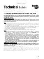
WARNING! Please READ and follow these instructions to
avoid personal injury or death:
When working on or around a vehicle, the following general
precautions should be observed at all times.
1. Park the vehicle on a level surface, apply the parking
brakes, and always block the wheels. Always wear safety
glasses.
2. Stop the engine and remove ignition key when working
under or around the vehicle. When working in the engine
compartment, the engine should be shut off and the ignition
key should be removed. Where circumstances require that
the engine be in operation, EXTREME CAUTION should
be used to prevent personal injury resulting from contact
with moving, rotating, leaking, heated or electrically charged
components.
3. Do not attempt to install, remove, disassemble or assemble
a component until you have read and thoroughly
understand the recommended procedures. Use only the
proper tools and observe all precautions pertaining to use
of those tools.
4. If the work is being performed on the vehicle’s air brake
system, or any auxiliary pressurized air systems, make
certain to drain the air pressure from all reservoirs before
beginning ANY work on the vehicle. If the vehicle is
equipped with an AD-IS
™
air dryer system or a dryer
reservoir module, be sure to drain the purge reservoir.
5. Following the vehicle manufacturer’s recommended
procedures, deactivate the electrical system in a manner
that safely removes all electrical power from the vehicle.
6. Never exceed manufacturer’s recommended pressures.
7. Never connect or disconnect a hose or line containing
pressure; it may whip. Never remove a component or plug
unless you are certain all system pressure has been
depleted.
8. Use only genuine Bendix
®
replacement parts, components
and kits. Replacement hardware, tubing, hose, fittings, etc.
must be of equivalent size, type and strength as original
equipment and be designed specifically for such
applications and systems.
9. Components with stripped threads or damaged parts
should be replaced rather than repaired. Do not attempt
repairs requiring machining or welding unless specifically
stated and approved by the vehicle and component
manufacturer.
10.Prior to returning the vehicle to service, make certain all
components and systems are restored to their proper
operating condition.
11. For vehicles with Antilock Traction Control (ATC), the ATC
function must be disabled (ATC indicator lamp should be
ON) prior to performing any vehicle maintenance where
one or more wheels on a drive axle are lifted off the ground
and moving.

Symptom: What it may indicate: What you should do:
20
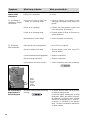
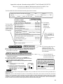
2.2 Oil leaking
from compressor:
(a)Excessive leak at head gasket.
(b)Leak at bottom cover plate.
(c)Leak at internal rear flange gasket.
(d)Leak through crankcase.
(e)(If unable to tell source of leak.)
ð Go to Test 1 on page 29.
ð Reseal bottom cover plate using RTV
silicone sealant.
ð Replace compressor.
ð Replace compressor.
ð Clean compressor and check periodically.
Air brake charging system functioning
normally.
ð Air dryers remove water and oil from the
air brake charging system.
Check that regular maintenance is being
performed. Return the vehicle to service.
An optional kit (Bendix piece number
5011327 for the Bendix
®
AD-IS
™
or AD-IP
™
air dryers, or 5003838 for the Bendix
®
AD-9
™
air dryer) is available to redirect the
air dryer exhaust.
3.0 Oil at air dryer
purge/exhaust or
surrounding area
(c)
2.0 Oil on the
Outside of the
Compressor
Find the source and repair. Return the vehicle
to service.
ð Repair or replace as necessary. If the
mounting bolt torques are low, replace the
gasket.
ð Replace the fitting gasket. Inspect inlet
hose and replace as necessary.
ð Replace gasket or fitting as necessary to
ensure good seal.
ð Inspect and repair as necessary.
Engine and/or other accessories
leaking onto compressor.
(a)Leak at the front or rear (fuel
pump, etc.) mounting flange.
(b)Leak at air inlet fitting.
(c)Leak at air discharge fitting.
(d)Loose/broken oil line fittings.
2.1 Oil leaking at
compressor / engine
connections:
(a)
ð
ð
Head
gasket
and rear
flange
gasket
locations.
(c)
La pagina sta caricando ...
La pagina sta caricando ...
La pagina sta caricando ...
La pagina sta caricando ...
La pagina sta caricando ...
La pagina sta caricando ...
La pagina sta caricando ...
La pagina sta caricando ...
La pagina sta caricando ...
La pagina sta caricando ...
La pagina sta caricando ...
La pagina sta caricando ...
La pagina sta caricando ...
La pagina sta caricando ...
La pagina sta caricando ...
La pagina sta caricando ...
La pagina sta caricando ...
La pagina sta caricando ...
La pagina sta caricando ...
La pagina sta caricando ...
-
 1
1
-
 2
2
-
 3
3
-
 4
4
-
 5
5
-
 6
6
-
 7
7
-
 8
8
-
 9
9
-
 10
10
-
 11
11
-
 12
12
-
 13
13
-
 14
14
-
 15
15
-
 16
16
-
 17
17
-
 18
18
-
 19
19
-
 20
20
-
 21
21
-
 22
22
-
 23
23
-
 24
24
-
 25
25
-
 26
26
-
 27
27
-
 28
28
-
 29
29
-
 30
30
-
 31
31
-
 32
32
-
 33
33
-
 34
34
-
 35
35
-
 36
36
-
 37
37
-
 38
38
-
 39
39
-
 40
40


BENDIX TU-FLO 1000 Manuale utente
- Categoria
- Compressori d'aria
- Tipo
- Manuale utente
in altre lingue
- English: BENDIX TU-FLO 1000 User manual
Altri documenti
-
DeWalt DPC10QTC Manuale utente
-
DeWalt DPC10RC Manuale utente
-
Senco PC1010N Operating Instructions Manual
-
BendPak RS7580H-603 Manuale del proprietario
-
Maserati Bora (Italian - English) Manuale del proprietario
-
KYMCO 125 AGILITY CITY Manuale utente
-
Yamaha Rhino 450 YXR45FAV Manuale utente
-
Enerpac VE42AM Repair Service Instructions
-
-