
Guide d'information rapide
Schnellstart-Handbuch
Guida introduttiva rapida
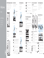
Inserting micro-SIM card — optional
Insérer une carte micro SIM — en option
Einsetzen der Micro-SIM-Karte – optional
Inserimento scheda micro-SIM - opzionale
3
2
Or | ou | Oder | Oppure |
Wireless antenna
Antenne sansfil
Wireless-Antenne
Antenna senza fili
Network connector
Port réseau
Netzwerkanschluss
Connettore di rete
Connect the network
Connexion au réseau | Anschließen des Netzwerks
Collegarsi alla rete |
4
Connect the display
Connectez l’écran | Bildschirm anschließen
Collegare lo schermo |
Install the Dell Edge Gateway on the wall mount
Installation du Dell Edge Gateway sur un support mural
Installieren des Dell Edge Gateway an einer Wandhalterung
Installare Dell Edge Gateway sul supporto da parete
1
Or | ou | Oder | Oppure |
the DIN rail mount
montage sur rail DIN
an einer DIN-Schienenhalterung
sul supporto guida DIN
NOTE: It is recommended to insert the micro-SIM card before powering on the
Dell Edge Gateway.
REMARQUE: il est recommandé d’insérer la carte micro-SIM avant de mettre le
DellEdge Gateway sous tension.
ANMERKUNG: Wir empfehlen, die Micro-SIM-Karte vor dem Einschalten des
DellEdge Gateway einzusetzen.
N.B.: Si consiglia di inserire la scheda micro-SIM prima di accendere il
DellEdgeGateway.
.:ةظحم
5 Connect and configure devices using the I/O
ports on your system
Connectez et configurez les périphériques à l’aide de ports d’E/S sur
votre système
Anschließen und Konfigurieren der Geräte mithilfe der E/A-Anschlüsse
an Ihrem System
Collegare e configurare i dispositivi utilizzando le porte I/O sul sistema.
NOTE: Turn on the corresponding dip switches to enable the corresponding
RS232/RS422/RS485 ports.
REMARQUE: allumez le commutateur DIP correspondant pour activer les
ports RS232/RS422/RS485 associés.
ANMERKUNG: Verstellen Sie die entsprechenden Dip-Schalter, um die
jeweiligen RS232/RS422/RS485-Anschlüsse zu aktivieren.
N.B.: Attivare i relativi interruttori DIP per abilitare le porte RS232/RS422/RS485.
:ةظحم
NOTE: The peripherals like wireless antenna, keyboard, and mouse are sold
separately.
REMARQUE: les périphériques tels que l’antenne sansfil, le clavier et la
souris sont vendus séparément.
ANMERKUNG: Die Peripheriegeräte wie Wireless-Antenne, Tastatur und
Maus sind separat erhältlich.
N.B.: Periferiche come antenna senza fili, tastiera e mouse vengono vendute
separatamente.
:ةظحم
NOTE: For more information on connecting the wireless antenna to Dell Edge
Gateway, see that documentation that is shipped with the wireless antenna.
REMARQUE: pour plus d’information sur la connexion de l’antenne sansfil au
Dell Edge Gateway, référez-vous à la documentation fournie avec l’antenne
sansfil.
ANMERKUNG: Weitere Informationen zum Anschließen der Wireless-Antenne
an das Dell Edge Gateway finden Sie in der Dokumentation im Lieferumfang
der Wireless-Antenne.
N.B.: Per maggiori informazioni sul collegamento dell'antenna senza fili al Dell
Edge Gateway, consultare la documentazione fornita con l'antenna senza fili.
:ةظحم
7 Complete the operating system setup
Terminer la configuration du système d’exploitation
Fertigstellen des Betriebssystem-Setups
Completare l'installazione del sistema operativo
NOTE: You can connect the power cable to the +24V AC/DC or +19 VDC
power adapter port.
REMARQUE: vous pouvez brancher le câble d’alimentation à une prise pour
adaptateur secteur +24V CA/CC ou +19 VCC.
ANMERKUNG: Sie können ein Netzkabel an den +24V AC/DC oder den +19
VDC-Netzadapteranschluss anschließen.
N.B.: È possibile collegare il cavo di alimentazione alla porta dell'adattatore
di alimentazione +24V AC/DC o +19 VDC.
+19:ةظحم
NOTE: The power adapter is sold sold separately.
REMARQUE: l’adaptateur d’alimentation est vendu séparément.
ANMERKUNG: Der Netzadapter ist separat erhältlich.
N.B.: L'adattatore di alimentazione è venduto separatamente.
:ةظحم
Or
ou
Oder
Oppure
+24V AC/DC
+19 VDC
Quick Start Guide
Dell Edge Gateway
5000 Series
Connect the keyboard and mouse
Connectez le clavier et la souris
Tastatur und Maus anschließen
Collegare la tastiera e il mouse
6 Connect to a power source and press the
power button
Branchez à une source d’alimentation et appuyez sur le bouton
d'alimentation
Anschließen einer Spannungsquelle und Drücken des Netzschalters
Collegare la fonte di alimentazione e premere l'Accensione

2015-11
Printed in China.
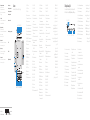
Features
Fonctionnalités | Funktionen | Funzioni |
1. USB 2.0 port
2. USB 2.0 port
3. HDMI port
4. Wireless antenna port
5. Intrusion Detection Connector
6. Wireless antenna port
7. Mobile broadband antenna port
8. Micro-SIM card slot (optional)
9. Mobile broadband antenna port
10. Power module expansion port
11. +24V AC/DC Power adapter port
12. +19 VDC Power adapter port
13. Power button
14. Earth ground
15. RS232 port
16. CANbus port (optional)
17. RS422/485 port
18. RS485 port
19. RS485 port
20. USB 3.0 port
21. Network port
22. Network port
23. I/O module expansion port
1. USB2.0-Anschluss
2. USB2.0-Anschluss
3. HDMI-Anschluss
4. Anschluss für die Wireless Antenne
5. Anschluss für die
Eindringlingserkennung
6. Anschluss für die Wireless Antenne
7. Anschluss für die Mobiles
Breitband-Antenne
8. Steckplatz für die Micro-SIM-Karte
(optional)
9. Anschluss für die Mobiles
Breitband-Antenne
10. Anschluss für die
Netzteilerweiterung
11. Anschluss für den +24V AC/DC-
Netzadapter
12. Anschluss für den +19 VDC-
Netzadapter
13. Betriebsschalter
14. Erdanschluss
15. RS232-Anschluss
16. CANbus-Anschluss (optional)
17. RS422/485-Anschluss
18. RS485-Anschluss
19. RS485-Anschluss
20. USB3.0-Anschluss
21. Netzwerkanschluss
22. Netzwerkanschluss
23. Anschluss für das E/A-
Erweiterungsmodul
1. Port USB2.0
2. Port USB2.0
3. Port HDMI
4. Port d’antenne sansfil
5. Connecteur de détection des
intrusions
6. Port d’antenne sansfil
7. Port d’antenne mobile haut débit
8. Emplacement de la carte micro-
SIM (en option)
9. Port d’antenne mobile haut débit
10. Port d’extension du module
d’alimentation
11. Prise pour adaptateur secteur
+24VCA/CC
12. Prise pour adaptateur secteur
+19VDC
13. Bouton d’alimentation
14. Mise à la terre
15. Port RS232
16. Port CANbus (en option)
17. Port RS422/485
18. Port RS485
19. Port RS485
20. Port USB3.0
21. Port réseau
22. Port réseau
23. Port d’expansion du module d’E/S
1. Porta USB 2.0
2. Porta USB 2.0
3. Porta HDMI
4. Porta antenna senza fili
5. Connettore di rilevamento
dell'intrusione
6. Porta antenna senza fili
7. Porta antenna per la banda larga
mobile
8. Slot per la scheda micro-SIM
(opzionale)
9. Porta antenna per la banda larga
mobile
10. Porta di espansione del modulo di
potenza
11. Porta adattatore di alimentazione
+24V AC/DC
12. Porta adattatore di alimentazione
+19 VDC
13. Accensione
14. Messa a terra
15. Porta RS232
16. Porta CANbus (opzionale)
17. Porta RS422/485
18. Porta RS485
19. Porta RS485
20. Porta USB 3.0
21. Porta di rete
22. Porta di rete
23. Porta di espansione del modulo I/O
1 .
2 .
3 .
4 .
5 .
6 .
7 .
8 .
9 .
10 .
11 .
12 .+19
13 .
14 .
15 .
16 .
17 .
18 .
19 .
20 .
21 .
22 .
23 .
1. Cloud connection status light
2. Blutooth status light
3. Wireless status light
4. Mobile broadband status light
5. Power status light
6. RS232 port status light
7. CANbus port status light
8. RS422/485 port status light
9. RS485 port status light
10. RS485 port status light
11. Network status light
12. Network status light
1. Indicatore di stato del
collegamento al cloud
2. Indicatore di stato del Bluetooth
3. Indicatore stato del rilevatore di
reti senza fili
4. Indicatore di stato della banda
larga mobile
5. Indicatore di stato dell'alimentazione
6. Indicatore di stato della porta RS232
7. Indicatore di stato della
portaCANbus
8. Indicatore di stato della porta
RS422/485
9. Indicatore di stato della porta RS485
10. Indicatore di stato della porta RS485
11. Indicatore di stato della rete
12. Indicatore di stato della rete
1. Cloud-Verbindung-Statusanzeige
2. Bluetooth-Statusanzeige
3. Wireless-Statusanzeige
4. Mobiles Breitband-Statusanzeige
5. Netzspannung-Statusanzeige
6. RS232-Anschluss-Statusanzeige
7. CANbus-Anschluss-Statusanzeige
8. RS422/485-Anschluss-Statusanzeige
9. RS485-Anschluss-Statusanzeige
10. RS485-Anschluss-Statusanzeige
11. Netzwerk-Statusanzeige
12. Netzwerk-Statusanzeige
1. Voyant d’état de la connexion
auCloud
2. Voyant d’état du Blutooth
3. Voyant d'état du sans fil
4. Voyant d’état du haut débit mobile
5. Voyant d’état de l’alimentation
6. Voyant d’état du port RS232
7. Voyant d’état du port CANbus
8. Voyant d’état du port RS422/485
9. Voyant d’état du port RS485
10. Voyant d’état du port RS485
11. Voyant d’état du réseau
12. Voyant d’état du réseau
1 .
2 .
3 .
4 .
5 .
6 .
7 .
8 .
9 .
10 .
11 .
12 .
10
2
3
23
12
34
56
7
9
8
11
12
13 14 15 16 17 18 19 20 21 22
Dell Edge Gateway LEDs
Technologie LED Dell Edge Gateway | Dell Edge Gateway-LEDs
LED di Dell Edge Gateway |
6
7
8
9
10
11
12
12345
Product support and manuals
Support produits et manuels
Produktsupport und Handbücher
Supporto tecnico e manuali del prodotto
Dell.com/support
Dell.com/support/manuals
Dell.com/support/windows
Dell.com/support/linux
Contact Dell
Contacter Dell | Kontaktaufnahme mit Dell
Contattare Dell | Dell
Dell.com/contactdell
Regulatory and safety
Réglementations et sécurité
Sicherheitshinweise und Zulassungsinformationen
Normative e sicurezza
Dell.com/regulatory_compliance
Regulatory model
Modèle réglementaire | Muster-Modellnummer
Modello di conformità |
N01G
Regulatory type
Type réglementaire | Muster-Typnummer
Tipo di conformità |
N01G001
Computer model
Modèle de l’ordinateur | Computermodell
Modello computer |
Dell Edge Gateway 5000
© 2015 Dell Inc.
© 2015 Microsoft Corporation.
-
 1
1
-
 2
2

