
/PERATOR@S MANUAL
GB
).3425#4)/.3 &/2 02/$5#4 $%,)6%29 0AGE
4RANSLATION OF THE ORIGINAL /PERATING -ANUAL
Ihre / Your / Votre • Masch.Nr. • Fgst.Ident.Nr.
.R 99 2161.GB.80I.0
Tedder
HIT 95 A
(Type 2164 : +..01001)
HIT 105 A
(Type 2161 : +..01001)

ALLG./BA SEITE 2 / 0000-GB
Important information concerning Product
Liability.
According to the laws governing product liability, the manufacturer and dealer are obliged to hand the
operating manual to the customer at the time of sale, and to instruct them in the recommended operating,
safety, and maintenance regulations. Confirmation is necessary to prove that the machine and operating
manual have been handed over accordingly.
For this purpose,
- document A is to be signed and sent to Pöttinger,
- document B remains with the dealer supplying the machine,
- and the customer receives document C.
In accordance with the laws of product liability, every farmer is an entrepreneur.
According to the laws of product liability, property damage is damage caused by a machine and not to
it. An excess of Euro 500 is provided for such a liabilioty.
In accordance with the laws of product liability, entrepreneurial property damages are excluded from
the liability.
Attention! Should the customer resell the machine at a later date, the operating manual must be given
to the new owner who must then be instructed in the recommended regulations referred to herein.
GB Dear Farmer
You have just made an excellent choice. Naturally we are very happy
and wish to congratulate you for having chosen Pöttinger. As your
agricultural partner, we offer you quality and efficiency combined with
reliable servicing.
In order to assess the spare-parts demand for our agricultural machines
and to take these demands into consideration when developing new
machines, we would ask you to provide us with some details.
Furthermore, we will also be able to inform you of new developments.

Dokument D
GB-0600 Dokum D Anbaugeräte
PÖTTINGER Landtechnik GmbH
Industriegelände 1
A-4710 Grieskirchen
Tel. 07248 / 600 -0
Telefax 07248 / 600-2511
T Machine checked according to delivery note. All attached parts removed. All safety equipment, drive shaft and operating
devices at hand.
T Operation and maintenance of machine and/or implement according to operating instructions explained to the customer.
T Tyres checked re. correct pressure.
T Wheel nuts checked re. tightness.
T Drive shaft cut to correct lenght.
T *VYYLJ[WV^LY[HRLVɈZWLLKPUKPJH[LK
T Fitting to tractor carried out: to three-point linkage
T Trial run carried out and no defects found.
T Functions explained during trial run.
T Pivoting in transporting and operating position explained.
T Information given re. optional extras.
T Absolute need to read the operating manual indicated.
Please check. X
According to the product liability please check the above mentioned items.
INSTRUCTIONS FOR
PRODUCT DELIVERY
GB
In order to prove that the machine and the operating manual have been properly delivered, a confirmation is necessary.
For this purpose please do the following:
- sign the document A and send it to the company Pöttinger or via the internet to www.poettinger.at
- document B stays with the specialist factory delivering the machine.
- document C stays with the customer.

GB
- 4 -
0800-GB-INHALT_2161
TABLE OF CONTENTS
¼¾ìâàç
ËÞÜèææÞçÝÚíâèçì
ßèëðèëäìÚßÞíò
ºååéèâçíìëÞßÞëâçà
íèìÚßÞíòâçíáâì
æÚçîÚåÚëÞ
âçÝâÜÚíÞÝÛòíáâì
ìâàç§
ÆÞÚçâçàèßðÚëçâçàìâàçì
ÍáÞ ¼¾ ìâàç¥ ðáâÜá âì ÚßßâñÞÝ Ûò íáÞ æÚçîßÚÜíîëÞë¥ âçÝâÜÚíÞì èîíðÚëÝåò íáÚí íáâì æÚÜáâçÞ
ÜèçßèëæìíèíáÞÞçàâçÞÞëâçààîâÝÞåâçÞëÞàîåÚíâèçìÚçÝíáÞèíáÞëëÞåÞïÚçí¾ÎàîâÝÞåâçÞì§
¾Î½ÞÜåÚëÚíâèçèß¼èçßèëæâíò»òìâàçâçàíá޾νÞÜåÚëÚíâèçèß¼èçßèëæâíò¥íáÞæÚçîßÚÜíîëÞë
ÝÞÜåÚëÞìíáÚííáÞæÚÜáâçÞÛÞâçàÛëèîàáíâçíèìÞëïâÜÞÜèæéåâÞìðâíáÚååëÞåÞïÚçíìÚßÞíòÚçÝ
áÞÚåíáëÞêîâëÞæÞçíì§
½èçèíÞçíÞëëèíèëÚëÞÚðáâåÞÝëâïâçà
æèíèëâìëîççâçà§
ÇÞïÞëëÞÚÜáâçíèíáÞÜëîìáâçàÝÚçàÞë
ÚëÞÚÚìåèçàÚìéÚëíìæÚòæèïÞ§
ÌíÚò ÜåÞÚë èß ìðâçàâçà ÚëÞÚ èß
âæéåÞæÞçíì§
495.173
ÍÚÛåÞèßÜèçíÞçíì
CE sign ...................................................................... 4
Meaning of warning signs.......................................... 4
ATTACHING TO THE TRACTOR
Attachment to tractor ................................................ 5
Hydraulic connection ................................................. 5
Drive shaft .................................................................. 5
Lowering .................................................................... 6
WORKING- AND TRANSPORTPOSITION
Conversion from working to transport position (from
2007 model) ............................................................... 7
Conversion from transport to working position (from
2007 model) ............................................................... 8
Conversion from working to transport position (up to
2006 model) ............................................................... 9
Conversion from transport to working position (up to
2006 model) ............................................................. 10
Driving on public roads ............................................ 11
OPERATION
General guidelines for working with the machine .... 12
Hydraulic control device (ST) ................................... 12
Raising front rotary units.......................................... 12
Adjustment of rotor inclination ................................ 13
Adjustment of tines .................................................. 13
Setting the feeler wheel ........................................... 13
Adjustment of trailing wheels .................................. 13
Trap sheet 1) ............................................................ 14
ADJUSTMENTS
Adjustments before operation ................................. 15
Adjusting inclination angle of rotary units ................ 15
MAINTENANCE
Safety point ............................................................. 18
General maintenance hints ...................................... 18
Cleaning of machine parts ....................................... 18
Parking in the ope .................................................... 18
Winter storage ......................................................... 18
Drive shafts .............................................................. 18
Hydraulic unit ........................................................... 18
Maintenance and repair ........................................... 19
Lubrication points .................................................... 19
Intake transmission ................................................. 19
Changing tines ......................................................... 20
Tine adjustment ....................................................... 20
TECHNICAL DATA
Tecnical Data ........................................................... 21
Position of Vehicle Identification Plate .................... 21
The defined use of the rotary tedder ....................... 21
SUPPLEMENT
Recommendations for work safety ......................... 24
Driveshaft ................................................................. 25
Lubrication chart ...................................................... 28
Lubricants ................................................................ 29
Hydraulicplain .......................................................... 31

- 5 -
0600_GB-Anbau_2162
GB
Safet hints:
see supplement-A1
points (8a. - 8i.)
1) Only necessary when used with optional extras
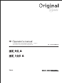
Drive shaft
Before operation, check lengths of drive shafts and adapt
if necessary (see chapter "Adaption of Drive Shaft" in
supplement B also).
Hydraulic connection
There must be at least a double-action hydraulic
connection available on the tractor.
Connecting hydraulic system to the tractor
- Only connect hydraulic system to the tractor when
stopcock is closed (position A).
EW1) Connect the plug-in connection with the ”red” dust
cap to the single action control valve.
DW Connect both plug-in connections with the ”blue”
dust caps to the double action control valve.
DW
DW
EW
TD44/94/1
A
E
TD 26/92/16
s
h
0
ST
Attachment to tractor
1. Attach shaft to tractor´s linkage drawbar.
Important!
-
The tractor linkage drawbar must be movable (A-B)
- Left and right lifting struts (4) must be of equal
length.
2. Secure fixing bolts using linch pin (V).
3. Fix the hydraulic lower link (5) in such a way that
the machine cannot swing out sideways.
4. Raise jackstand (10) and secure with bolt.
Up to 2005 model
From 2006 model
Important!
Always connect
wide angle joint
to tractor, not to
machine! 1)
ATTACHING TO THE TRACTOR

- 6 -
0600_GB-Abstellen_2162
GB
LOWERING THE MACHINE
- Close stopcock on every connector (pos. A) and then
disconnect hydraulic lines from tractor.
- Disconnect appliance from tractor.
Attention!
When parking machine in working position,
ensure stability (tipping).
Should problems occur when disconnecting:
- Move servo-valve (ST) briefly to "lower" position (s).
Doing this will reduce any possible pressure remaining
in the connector and allows a trouble-free disconnection
of the hydraulic lines.
The machine can be lowered both from the working position
and from the transport position.
- Park machine stabily!
- Secure implement from rolling using wheel
chocks!
- Swing support stand down (5a)
- secure with locking pin (B)
Up to 2005 model
From 2006 model
- Pull off drive shaft and rest on support.
Do not rest drive shaft on safety chain!
Attention!
Park machine
stabily!
Secure implement
from rolling!
Lowering
A
E
TD 26/92/16
s
h
0
ST
Pos. E
Pos. A

- 7 -
0701_GB-Arbeitsstellung_2162
GB
WORKING- AND TRANSPORTPOSITION
Conversion from working to transport position (from 2007 model)
Attention!
Safet hints: see
supplement -A1
points (8a. - 8i.)
Changing from
working position
to transport
position is only to
be carried out on
even, firm ground.
The tractor must
be standing still
or travelling
slowly forwards.
Tractor must not
be under brakes
during swivelling
procedure.
A
E
TD44/94/8
ST
Note!
Trailing wheels (N)
set themselves in
correct position
only after travel
begins.
Attention!
Drive must not
be switched on
when in transport
position!
- risk of damage
Turn drive off!
Swivelling procedure:
1. Extend drawbar cylinder (1) until frame is standing
approx. horizontal
2. Begin swivelling procedure
Make sure that swivel area is free and that nobody is
standing in the danger area.
- Pull valve lever (3) forward using rope
- Use double action control valve (ST)
- Move tractor slowly forward
- Swivel rotary units completely in
Note!
Operate control valve (ST) until
- the hydraulic wheels (H) are completely turned
out
or (for machines with feeler wheels 1))
- all feeler wheels are folded up
3. Release the rope
Note!
Move hydraulic control valve (ST) into float
position when transporting

- 8 -
0701_GB-Arbeitsstellung_2162
GB
WORKING- AND TRANSPORTPOSITION
Changing from working position to
transport position is only to be carried out
on even, firm ground.
The tractor must be standing still or
travelling slowly forwards.
Note!
Do not swivel to contour line!
Fold feeler wheel (T) down
Attention!
Stand clear of
implement‘s
swivel range.
Tractor must not
be under brakes
during swivelling
procedure.
Conversion from transport to working position (from 2007 model)
Swivelling procedure:
1. Extend drawbar cylinder (1) out (1 cm)
- Hinged bracket (2) is released
2. Begin swivelling procedure
Make sure that swivel area is free and that nobody is
standing in the danger area.
- Pull valve lever (3) forward using rope
- Use double action control valve (ST)
- Swivel rotary units out into working position.
Note!
Operate control valve (ST) until the machine
is completely swivelled out. Carry out this
procedure in one constant operation
3. Release the rope

- 9 -
0701_GB-Arbeitsstellung_2162
GB
WORKING- AND TRANSPORTPOSITION
Activate control valve (ST) until
- hydraulic wheels (H) are completely turned out
For machines with feeler wheels 1)
- all feeler wheels are folded up.
Attention!
Trailing wheels (N) set themselves in correct
position only after travel begins.
Attention!
Tractor must not be under brakes during
swivelling procedure.
Attention!
Drive must not be switched on when in
transport position!
- risk of damage!
Turn drive off!
1. Drive tractor forward
- all wheels must be trailing (H).
2. Make sure that swivel area is free and that nobody is
standing in the danger area.
3. Swivel rotary unit to the rear.
Use double action control valve (ST)
4. Close stop valves (position A)
For safety, travel on roads only with stop valves
closed!
A
E
TD44/94/8
ST
Conversion from working to transport position (up to 2006 model)
Attention!
Safet hints: see
supplement -A1
points (8a. - 8i.)
Changing from
working position
to transport
position is only to
be carried out on
even, firm ground.
The tractor must
be standing still
or travelling
slowly forwards.

- 10 -
0701_GB-Arbeitsstellung_2162
GB
WORKING- AND TRANSPORTPOSITION
Attention!
Stand clear of
implement‘s
swivel range.
Conversion from transport to working position (up to 2006 model)
Attention!
Tractor must not be under brakes during
swivelling procedure.
• Changing from working position to
transport position is only to be carried
out on even, firm ground.
The tractor must be standing still or
travelling slowly forwards.
Note!
Do not swivel to contour line!
1. Open stop valve (pos. E)
2. Fold feeler wheel (T) down
A
E
TD44/94/8
ST
Pos. E
Pos. A
3. Make sure that swivel area is free and that
nobody is standing in the danger area.
4. Swivel rotary units out into working position.
• Use double action control valve (ST)
5. Close stop valves (position A)

- 11 -
0700_GB-Straßenfahrt_2162
GB
ROAD TRAVEL
• Observe the official regulations of your country.
• Travelling on open roads may only be carried out as
described in chapter "Transport position".
• Close all hydraulic circuits (A).
• Protection devices must be in proper condition.
• Before travelling bring all swivelling parts into their
correct positions and secure against dangerous
changes to position.
• Check that lighting functions before travelling.
• Important information can also be found in the
supplement of this operating manual.
Driving on public roads
Hydraulic lower link
- Fix the hydraulic lower link (U) in such a way that the
machine cannot swing out sideways.
Attention!
Observe the official
regulations of
your country.

- 12 -
0700_GB-Einsatz_2162
GB
OPERATION
Safety hints!
(see supplement-
A1 points 1, 2, 3
and 4)
Important points befor starting work
1. Turn p.t.o. on.
Turn the p.t.o. on only when all safety devices (coverings,
protective aprons, casings, etc.) are in proper condition
and attached to the implement in the correct protective
positions.
2. Switch-on the machine only in working position
and do not exceed the prescribed power take-
off speed (for example max. 540 rpm).
P.t.o. speed max. = 540 rpm
The most favourable p.t.o. rpm is about 450 rpm.
Caution!
Do not enter rotor area while driving motor is
running.
- Choose the speed of travel so that all crops are picked
up thoroughly.
- In cases of overloading, shift down one gear.
495.173
Hydraulic control device (ST)
- Put hydraulic control device (ST) into "free gear" (floating
position or "lower").
ST
General guidelines for working with the machine
Raising front rotary units
When driving over obstacles or out of working area, front
rotary units can be raised using drawbar cylinder
Tines are then away from the ground and therefore
protected against damage

- 13 -
0700_GB-Einsatz_2162
GB
OPERATION
Adjustment of rotor inclination
Trailing axles can be adjusted within swivel range with
excentric (A).
- loosen screw (B)
- turn excentric (A) with ring spanner
- 1 stage = 3° rotary inclination adjustment
- tighten screw (B)
Additional fixing possibilities in 2 positions
Adjustment of tines
It is also important that tine inclination
is correct (see chapter "USE").
S1S2
80
TD 16/96/2
R
A lot of fodder = greater angle.
Not much fodder = smaller angle.
Adjustment of trailing wheels
Raise or reduce spring tension with spring (F)
- tighten or loosen screw (M)
Setting the feeler wheel
• Select a gap as small as possible between feeler wheel
and tines (A)
- Insert pin (B) in relevant position depending on amount
of forage
- then tighten bearing pipe free from play with tension
lever (H).
A
H
B
175-04-14

- 14 -
0700_GB-Einsatz_2162
GB
OPERATION
B
092-06-04
Trap sheet 1)
- Secure the trap sheet for operation and transport with bolts (B)
(Only necessary for variants with manual swath apron)
1) Optional extra

- 15 -
0701_GB-Einstellungen_2161
GB
ADJUSTMENTS
1) O
ptional equipment
Important!
The
distance (X)
between drive shaft and linkage
drawbar should be at least 120 mm when in working
position (standard). Take note of distance ”X” particularly
when travelling over humps.
Attention!
Do not travel in reverse in working
position!
(If necessary only slowly and particularly
carefully)
Set draw bar height
- Distance
H = 390 mm
Adjustments before operation
Caution!
All work in the
immediate area
of the rotors may
only be carried
out when the
p.t.o. is switched
off.
Adjusting inclination angle of rotary units
Adjust rotary inclination (from 2007 model)
Inclination adjustment takes place through:
- hydraulic cylinder on drawbar
- using double-action hydraulic control valve
Normal adjustment takes place through:
- turning the threaded spindle (1)
Setting machines without feeler wheel
EUROHIT 95 A
Setting measurement T = 60 mm “flat”
T = 37 mm “steep”
EUROHIT 105 A
Setting measurement T = 50 mm “flat”
T = 37 mm “steep”
Note!
Swivelling bracket (K) must be fitted in hole (1)
Setting machines with feeler wheel 1)
EUROHIT 95 A, EUROHIT 105 A
Setting measurement T = 15 mm “flat”
T = 0 mm “steep”
Note!
Swivelling bracket (K) must be fitted in hole (2)
K
2
06-07-07
K
1
06-07-08
1

- 16 -
0701_GB-Einstellungen_2161
GB
ADJUSTMENTS
1) O
ptional equipment
Set working depth (from 2006 model)
Setting working depth is carried out by
- turning the threaded spindle (1)
Setting machines without feeler wheel
EUROHIT 95 A
Setting measurement T = 60 mm “flat”
T = 37 mm “steep”
EUROHIT 105 A
Setting measurement T = 50 mm “flat”
T = 37 mm “steep”
Setting machines with feeler wheel 1)
EUROHIT 95 A, EUROHIT 105 A
Setting measurement T = 15 mm “flat”
T = 0 mm “steep”
Optimum setting is when
- pin (B) is located almost in the middle of slot (L)
Note!
For machines with feeler wheel and setting T =
0 mm “steep”, the height of the ploughing disc
can be lowered to 330 mm if need be.
Caution!
All work in the
immediate area
of the rotors may
only be carried
out when the
p.t.o. is switched
off.

- 17 -
0701_GB-Einstellungen_2161
GB
ADJUSTMENTS
1) O
ptional equipment
Set working depth (up to 2005 model)
Setting working depth is carried out by
- turning the threaded spindle (1)
Setting machines without feeler wheel
- inserting bracket in position “H”
- Setting measurement T = 20 mm “flat”
T = 5 mm “steep”
Setting machines with feeler wheel 1)
- inserting bracket in
position “V”
- Setting measurement T = 31 mm “flat”
T = 20 mm “steep”
Optimum setting is when
- pin (B) is located almost in the middle of slot (L)

- 18 -
GB
0400_GB-BA-Allg. Wartung
Parking in the ope
When parking in the open for
long periods of time, clean
piston rods and then coat
with grease.
FETT
TD 49/93/2
Safety
points!
• Turn engine off
when adjustment,
service and repair
work is to be
done.
• Do not work un-
der the machine
without safe
support.
• Retighten all
screws after the
first hours of
operation..
General maintenance hints
In order to keep the implement in
good condition after long periods
of operation, please observe the
following points:
- Tighten all screws after the first
hours of operation.
In particular check:
- blade screws on the mowers
- tine screws on the swather and tedder.
Spare part
a. The original components and accessories have
been designed especially for these machines and
appliances.
b. We want to make it quite clear that components and
accesories that have not been supplied by us have
not been tested by us.
c. The installation and/or use of such products can,
therefore, negatively change or influence the
construction characteristics of the appliance. We are
not liable for damages caused by the use of components
and accessories that have not been supplied by us.
d. Alterations and the use of auxiliary parts that are
not permitted by the manufacturer render all liability
invalid.
Cleaning of machine parts
Attention! Do not use high-pressure washers for the
cleaning of bearing- and hydraulic parts.
- Danger of rust!
- After cleaning, grease the machine according to the
lubrication chart and carry out a short test run.
- Cleaning with too high pressure may do damage to
varnish.
Safety point
• Turn engine off when adjustment, service and repair
work is to be done.
Hydraulic unit
Caution! Danger of injury or infection!
Under high pressure, escaping fluids can penetrate
the skin. Therefore seek immediate medical help!
After the first 10 operating hours and then every
consecutive 50 operating hours
- Check the hydraulic unit and lines for tightness and
retighten screw connections if necessary.
Before operation
- Check hydraulic hoses for wear.
Replace worn or damaged hydraulic hoses immediately.
The replacement hoses must meet the manufacturer’s
technical requirements.
Hose lines are subject to natural ageing. The period of
use should not exceed 5 – 6 years.
Winter storage
- Thoroughly clean machine before storage.
- Put up protection against weather.
- Change or replenish gear oil.
- Protect exposed parts from rust.
- Lubricate all greasing points according to lubrication
chart.
Drive shafts
- see notes in the supplement
For maintenance please note!
The instructions in this operating manual are always
valid.
In case there are no special instructions available, then
the notes in the accompanying drive shaft manufacturer´
instructions are valid.
Repair In-
structions
Please refer to
repair instructions
in supplement (if
available)
MAINTENANCE

- 19 -
0401_GB-Wartung_2162
MAINTENANCE GB
Maintenance and repair
In order to keep the implement in good condition even
after a longer service life, please observe the following
advice.
- Retighten all screws after the first hours of
operation.
In particular the tine connections (12 kpm), the tine
bar connections (9 kpm) and the slewing headstock
connections should be checked.
- Always keep the stipulated air pressure in the tyres.
- Grease the lubrication points in accordance with the
regulation (see lubrication schedule).
Grease the lubrication nipples with universal grease
after every 20 hours of operation.
- Before leaving the machine over winter, oil all the joints
well and grease all bearings.
Lubrication points
Symbols have been stuck on the machine at various points.
These indicate one or more lubrication points.
• Grease lubrication points
according to lubrication chart.
Intake transmission
- Change oil after the first 50 operating hours.
- Under normal operating conditions, oil is to be changed
annually.
- Change oil after 100h at the latest.
Beware!
Retighten all
screws after the
first hours of
operation.
FETT
1 Oil fill screw with ventilation
2 Oil level screw
3 Oil drain screw
Important!
- When measuring oil level (2) machine must be standing
exactly level.
0,8 Liter
SAE 90

- 20 -
0401_GB-Wartung_2162
MAINTENANCE GB
TD 7/95/3
Drehrichtung
direction of rotation
12 kpm
S1S2
80
TD 16/96/2
R
Tine adjustment
Tine position can be altered by turning the tine carrier
(80).
• Position "S1"
Standard position (ex factory)
• Position "S2"
For use under difficult conditions, e. g. with very
dense, awkward forage. This tine position increases
the strewing action.
• Direction of rotation "R"
Be aware of this when installing tines.
TD16/96/1
80
Changing tines
- Remove broken tine after loosening the hexagonal nut
and fit new tine.
- For correct fitting observe the direction of the rotors!
- Tighten hexagonal screw with 12 daNm (= 12 kpm).
La pagina si sta caricando...
La pagina si sta caricando...
La pagina si sta caricando...
La pagina si sta caricando...
La pagina si sta caricando...
La pagina si sta caricando...
La pagina si sta caricando...
La pagina si sta caricando...
La pagina si sta caricando...
La pagina si sta caricando...
La pagina si sta caricando...
La pagina si sta caricando...
La pagina si sta caricando...
La pagina si sta caricando...
-
 1
1
-
 2
2
-
 3
3
-
 4
4
-
 5
5
-
 6
6
-
 7
7
-
 8
8
-
 9
9
-
 10
10
-
 11
11
-
 12
12
-
 13
13
-
 14
14
-
 15
15
-
 16
16
-
 17
17
-
 18
18
-
 19
19
-
 20
20
-
 21
21
-
 22
22
-
 23
23
-
 24
24
-
 25
25
-
 26
26
-
 27
27
-
 28
28
-
 29
29
-
 30
30
-
 31
31
-
 32
32
-
 33
33
-
 34
34


Pottinger HIT 105 A Istruzioni per l'uso
- Tipo
- Istruzioni per l'uso
- Questo manuale è adatto anche per
in altre lingue
Documenti correlati
-
Pottinger HIT 130 A Istruzioni per l'uso
-
-
-
-
-
-
-
-
-