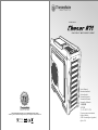
Thermaltake Chaser A71 Manuale utente
- Categoria
- Custodie per computer
- Tipo
- Manuale utente
La pagina sta caricando ...
La pagina sta caricando ...

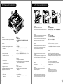
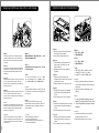
<160 mm
<344 mm
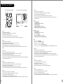
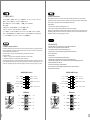
CPU Cooler Height Limitation VGA (Add- on card) Length Limitation
Warning!!
- Height limit for the CPU heatsink:
The height limit for the CPU heatsink is 160 mm (6.3 inches).
- Length limit for the VGA (graphics card):
The length limit for the VGA (graphics card) is 344 mm (13.6 inches).
- If you’re installing a top-front fan on the case, please do not install the first 5.25” bay device.
Warnung!!
- Höhenbeschränkung für CPU-Kühler:
Die Höhenbeschränkung für den CPU-Kühler liegt bei 160 mm (6.3 Zoll).
- Längenbeschränkung für die VGA (Grafikkarte):
Die Längenbeschränkung für die VGA (Grafikkarte) beträgt 344 mm (13,6 Zoll).
- Wenn Sie vorne oben im Gehäuse ein Gebläse anbringen, installieren Sie bitte nichts in den ersten 5,25 Zoll
Schacht .
Avertissement !
- Hauteur limite du dissipateur thermique du processeur :
La hauteur limite du dissipateur thermique du processeur est de 160 mm (6.3 pouces).
- Longueur limite de la carte VGA (carte graphique) :
La longueur limite de la carte VGA (carte graphique) est de 344 mm (13,6 pouces).
- Si vous installez un ventilateur dans la partie supérieure avant du boîtier, veuillez ne pas installer de périphérique
dans la première baie de 5,25 pouces.
Precaución
- Límite de altura para el disipador de calor de la CPU:
El límite de altura para el disipador de calor de la CPU es de 160 mm (6.3 pulgadas).
- Límite de longitud para la tarjeta gráfica (VGA):
El límite de longitud para la tarjeta gráfica (VGA) en de 344 mm (13,6 pulgadas).
- Si va a instalar un ventilador frontal superior en la carcasa, no instale el primer dispositivo de puerto de 5,25”.
Attenzione!
- Limite di altezza per il dissipatore di calore della CPU:
Il limite di altezza per il dissipatore di calore della CPU è 160 mm (6.3’’).
- Limite di lunghezza per la VGA (schede grafiche):
Il limite di lunghezza per la VGA (scheda grafica) è 344 mm (13,6’’).
- In caso di installazione di una ventola anteriore superiore sul case, non installare primo dispositivo vano da 5,25’’.
Atenção!!
- Limite de altura para o dissipador do CPU:
O limite de altura para o dissipador do CPU é 160 mm (6.3 polegadas).
- Limite de comprimento para VGA (placa gráfica):
O limite de comprimento para VGA (placa gráfica) é 344 mm (13,6 polegadas).
- Se estiver a instalar uma ventoinha na parte frontal superior da caixa, não instale o dispositivo da
primeira baía de 5,25”.
警告!!
- CPU散熱器的高度限制:
CPU散熱器的高度限制為160mm(6.3英吋)。
- VGA(顯示卡)的長度限制:
VGA(顯示卡)的長度限制為344mm(13.6英吋)。
- 如安裝機箱上面前方風扇,請勿安裝第一槽5.25”裝置。
警告!!
- CPU散热器的高度限制:
CPU散热器的高度限制为160mm(6.3英寸)。
- VGA(显卡)的长度限制:
VGA(显卡)的长度限制为344mm(13.6英寸)。
- 如安装机箱上面前方风扇,请勿安装第一插槽5.25”装置。
警告
- CPUヒートシンクの高さ制限:
CPUヒートシンクの高さ制限は160 mmです。
- VGA(グラフィックスカード)の長さ制限:
VGA(グラフィックスカード)の長さ制限は344 mmです。
- ケースにトップフロントファンを取り付ける場合、最初の5.25”ベイデバイスを取り付けないでください。
Внимание!
- Ограничение по высоте для радиатора ЦП.
Ограничение по высоте для радиатора ЦП составляет 160 мм (6.3 дюйма).
- Ограничение по длине для платы VGA (графическая плата).
Ограничение по длине для платы VGA (графическая плата) составляет 344 мм (13,6 дюйма).
- При установке верхнего вентилятора в передней части корпуса не устанавливайте устройство в пе
рвый отсек для 5,25-дюймовых устройств.
Uyarı!!
- CPU ısı alıcısı için yükseklik sınırı:
CPU ısı alıcısı için yükseklik sınırı 160 mm’dir (6.3 inç).
- VGA (grafik kartı) için uzunluk sınırı:
VGA (grafik kartı) için uzunluk sınırı 344 mm’dir (13,6 inç).
- Kasaya üst ön fanı takıyorsanız, lütfen ilk 5,25” bölmesine aygıt takmayın.
คำเตือน!!
- ขีดจำกัดความสูงสำหรับฮีตซิงก์ของ CPU:
ขีดจำกัดความสูงสำหรับฮีตซิงก์ของ CPU คือ 160 มม. (6.3 นิ้ว)
- ขีดจำกัดความยาวสำหรับ VGA (การ์ดแสดงผล):
ขีดจำกัดความยาวสำหรับ VGA (การ์ดแสดงผล) คือ 344 มม. (13.6 นิ้ว)
- ถ้าคุณกำลังติดตั้งพัดลมที่ส่วนบนด้านหน้าของเคส กรุณาอย่าติดตั้งอุปกรณ์ขนาด 5.25” ลงในช่องไดร์ฟช่องแรก
2 3
Warning and Notice
藍色線條為尺寸標示,請勿印刷上去!
產品料號
V P 4 0 0 0 S e r i e s C h a s e r A 7 1 說明書 1 3 /0 1 /24 A
產品名稱
印刷項目
子件料號
發稿日期
版本
騎馬釘2 8 8 0 X X X X X
書寫紙
單色 無無
其他特殊處理效果表面處理
2
厚度(g/m )
裝訂方式 材質頁數 印刷色彩
規格樣式
整本
MARKETING CHECK DESIGN
PRODUCT GM
其他特殊處理效果表面處理
2
厚度(g/m )
材質印刷色彩
封面樣式(當封 面 與 內 頁 樣 式不同時尚須填寫)
Peipei
刀模線
125 mm
176 mm

4
5
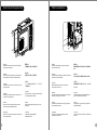
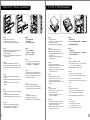
Side Panel Disassembly
English /
Remove the screws on the back of the chassis,
and open the side panel.
Deutsch /
Entfernen Sie die Schrauben auf der Rückseite
des Gehäuses und öffnen Sie das Seitenteil.
Français /
Enlevez les vis à l’arrière du châssis et ouvrez le
panneau latéral.
Español /
Extraiga los tornillos de la parte posterior de la
caja y abra el panel lateral.
Italiano /
Rimuovere le viti sulla parte posteriore dello
chassis e aprire il pannello laterale.
Português/
Remova os parafusos na parte de trás da caixa e
abra o painel lateral.
繁體中文 /
移除機殼後方螺絲,將側窗打開。
日本語 /
シャーシ背面のねじを取り外し、サイドパネ
ルを開きます。
Русский /
Открутите винты на задней стенке корпуса
и откройте боковую панель.
简体中文 /
卸除机壳后方螺丝,将侧窗打开。
Türkçe /
Kasanın arkasındaki vidaları çıkarın ve yan
paneli açın.
ภาษาไทย /
ถอดสกรูที่ด้านหลังของแชสซีส์
แล้วเปิดแผงด้านข้าง
English /
Place the power supply in proper location and
secure it with screws.
Deutsch /
Installieren Sie das Netzteil an seiner Position und
sichern Sie es mit Schrauben.
Français /
Mettez l'alimentation dans le bon endroit et
sécurisez-la avec des vis.
Español /
Coloque el suministro de alimentación en el lugar
adecuado y asegúrelo con tornillos.
Italiano /
Posizionare l'alimentatore in modo appropriato e
fissarlo utilizzando le viti.
Português/
Coloque a fonte de alimentação na devida
localização e aparafuse.
简体中文 /
恰当定位电源供应器位置并以螺丝安全固定。
日本語 /
電源装置を適切な場所に取り付け、ねじで固
定します。
Русский /
Установите блок питания в надлежащее
место и закрепите его винтами.
繁體中文 /
將電源供應器放在正確的位置,並用螺絲固定
鎖上。
Türkçe /
Güç kaynağını uygun konuma yerleştirin ve
vidalarla sabitleyin.
ภาษาไทย /
วางแหล่งจ่ายไฟในตำแหน่งที่เหมาะสมแล้วขันสกรู
ยึดให้แน่น
PSU Installation
藍色線條為尺寸標示,請勿印刷上去!
產品料號
V P 4 0 0 0 S e r i e s C h a s e r A 7 1 說明書 1 3 /0 1 /24 A
產品名稱
印刷項目
子件料號
發稿日期
版本
騎馬釘2 8 8 0 X X X X X
書寫紙
單色 無無
其他特殊處理效果表面處理
2
厚度(g/m )
裝訂方式 材質頁數 印刷色彩
規格樣式
整本
MARKETING CHECK DESIGN
PRODUCT GM
其他特殊處理效果表面處理
2
厚度(g/m )
材質印刷色彩
封面樣式(當封 面 與 內 頁 樣 式不同時尚須填寫)
Peipei
刀模線
125 mm
176 mm

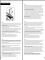
Motherboard Installation
English /
1.Lay down the chassis.
2.Install the motherboard in proper location and
secure it with screws.
Deutsch /
1.Legen Sie das Gehäuse auf die Seite.
2.Installieren Sie die Hauptplatine in ihrer
vorgesehenen Position und sichern Sie sie mit
Schrauben.
Français /
1.Posez à plat le châssis.
2.Installez la carte mère dans l'endroit approprié et
sécurisez-la avec des vis.
Español /
1. Tumbe el chasis.
2. Instale la placa madre en la ubicación adecuada
y asegúrela con tornillos.
Italiano /
1.Poggiare lo chassis.
2.Installare la scheda madre nella posizione
appropriata e fissarla con le viti.
Português/
1. Deixe a caixa.
2. Instale a motherboard no local adequado e
aparafuse.
繁體中文 /
1. 將機殼平放。
2. 將主機板放置在合適的位置並用零件包中之螺
絲固定。
日本語 /
1.シャーシを下に置きます。
2.マザーボードを適切な場所に取り付け、ねじで
固定します。
Русский /
1. Раскройте системный блок.
2. Установите материнскую плату в надлежащее
место и закрепите ее винтами.
简体中文 /
1. 放平机箱。
2. 在合适的位置安装主板并以螺丝安全固定。
Türkçe /
1.Kasayı yan yatırın.
2.Ana kartı uygun konuma takın ve vidalarla
sabitleyin.
ภาษาไทย /
1.วางแชสซีส์นอนลง
2.ติดตั้งเมนบอร์ดในตำแหน่งที่เหมาะสมแล้วขันสก
รูยึดให้แน่น
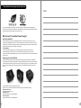
5.25" Device Installation
English /
1. Remove the 5.25” drive bay cover.
2. Place 5.25” device into the drive bay.
Note: Press the 5.25” tool-free mechanism to unlock the
device.
Deutsch /
1. Entfernen Sie die Abdeckung des 5,25 Zoll Schachts.
2. Platzieren Sie die 5,25 Zoll Einheit in den
Laufwerkschacht.
Anmerkung: Drücken Sie den 5,25 Zoll werkzeuglosen
Mechanismus, um die Einheit zu verriegeln.
Français /
1. Retirez le couvercle de la baie de lecteur 5.25"
2. Mettez le périphérique 5.25” dans la baie de lecteur.
Remarque : Appuyez sur le mécanisme sans outil de
5,25" pour déverrouiller le périphérique.
Español /
1. Extraiga la cubierta de la bahía de unidad de 5,25
pulgadas.
2. Coloque el dispositivo de 5,25 pulgadas en la bahía
de unidad.
Nota: Presione el mecanismo libre de herramienta de
5,25” para abrir el dispositivo.
6 7
Italiano /
1. Rimuovere il coperchio dell'alloggiamento dell'unità
da 5,25 pollici
2. Posizionare il dispositivo da 5,25” nell'alloggiamento
dell'unità.
Nota: Premere il meccanismo tool-free da 5,25” per
sbloccare il dispositivo.
Português/
1. Remova a cobertura da baía da unidade de 5,25”.
2. Coloque o dispositivo de 5,25” na baia da unidade.
Nota: Pressione o mecanismo de 5,25" sem utilizar
ferramentas para desbloquear o dispositivo.
繁體中文 /
1. 移除5.25”擴充槽的擋板。
2. 插入硬體裝置。
注意: 如需移除5.25”裝置,先按壓5.25”無螺機機構,再將
5.25”裝置往前推出。
日本語 /
1. 5.25”ドライブベイのカバーを取り外します。
2. 5.25” デバイスをドライブベイに取り付けます。
注: 5.25”工具不要メカニズムを押してデバイスをアンロ
ックします
Русский /
1. Снимите крышку 5,25 - дюймового отсека.
2. Установите 5,25-дюймовое устройство в отсек.
Примечание. Нажмите на не требующий использован
ия инструментов механизм отсека для 5,25-дюймов
ых дисководов, чтобы разблокировать устройство.
简体中文 /
1. 卸下 5.25” 驱动器槽盖。
2. 将 5.25” 设备放入驱动器槽。
注意: 如需移除5.25”设备,先按压5.25”免用工具机械装
置,再将5.25”设备往前推出
Türkçe /
1. 5.25” sürücü bölmesi kapağını çıkarın.
2. 5.25” aygıtı, sürücü bölmesinin içine yerleştirin.
Not: Aygıtın kilidini açmak için 5,25” araçsız
mekanizmayı bastırın.
ภาษาไทย /
1. ถอดฝาปิดช่องไดรฟ์ขนาด 5.25” ออก
2. ใส่อุปกรณ์ขนาด 5.25” เข้าในช่องไดร์ฟ
หมายเหตุ: กดตัวล็อคเครื่องมือขนาด 5.25"
เพื่อปลดล็อคอุปกรณ์
藍色線條為尺寸標示,請勿印刷上去!
產品料號
V P 4 0 0 0 S e r i e s C h a s e r A 7 1 說明書 1 3 /0 1 /24 A
產品名稱
印刷項目
子件料號
發稿日期
版本
騎馬釘2 8 8 0 X X X X X
書寫紙
單色 無無
其他特殊處理效果表面處理
2
厚度(g/m )
裝訂方式 材質頁數 印刷色彩
規格樣式
整本
MARKETING CHECK DESIGN
PRODUCT GM
其他特殊處理效果表面處理
2
厚度(g/m )
材質印刷色彩
封面樣式(當封 面 與 內 頁 樣 式不同時尚須填寫)
Peipei
刀模線
125 mm
176 mm
La pagina sta caricando ...

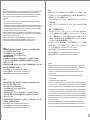
HDD Docking Station
English /
The top HDD Docking slot is embedded to enable ultra fast transfer (up to 6.0Gbps) of large data to a SATA
hard disk without having to use an external storage enclosure. To ensure proper operation, please make sure
the following settings are correct:
- Ensure all required drivers are installed for your motherboard or SATA controller card.
- Connect the SATA cable to an available SATA connector on the motherboard or SATA controller card.
- Connect the power cable to power supply.
- Ensure AHCI (Advanced Host Controller Interface) is enabled on your motherboard or SATA controller card.
The AHCI enables for “hotswap” capability of the SATA hard drives without having to turn off the computer
prior to connecting or disconnecting of the hard drive. Please follow instruction provided
by your motherboard or SATA controller card to enable the AHCI function.
If you are using a brand new hard drive, the hard drive will need to be initialized (formatted) before it is
accessible. For more information on how to initialize (format) a new hard drive, please refer to the hard drive
user manual or visit
System running on Windows 7: http://www.thermaltakeusa.com/Faq.aspx?ID=1143
System running on Windows Vista: http://www.thermaltakeusa.com/Faq.aspx?ID=1079
System running on Windows XP: http://www.thermaltakeusa.com/Faq.aspx?ID=1073
Deutsch /
Der obere Einführungsschlitz der HDD-Dockingstation ist eingelassen, um einen ultraschnellen Transfer (bis
zu 6,0 GB/s) von umfangreichen Daten zur SATA-Festplatte zu ermögichen, ohne dafür ein externes Gehäuse
verwenden zu müssen. Um einen ordnungsgemäßen Betrieb zu gewährleisten, stellen Sie bitte sicher, dass
die folgenden Einstellungen richtig sind:
- Stellen Sie sicher, dass alle erforderlichen Treiber für Ihr Mainboard oder SATA Controller-Karte installiert
sind.
- Verbinden Sie das SATA-Kabel mit einen freien SATA-Anschluss auf dem Mainboard oder der SATA
Controller-Karte.
- Verbinden Sie das Stromkabel mit dem Netzteil.
- Stellen Sie sicher, dass AHCI (Advanced Host Controller Interface) auf dem Motherboard oder der SATA-
Controller-Karte aktiviert ist. AHCI ermöglicht die "HotSwap"-Funktion der SATA-Festplatten, ohne dass
Sie den Computer ausschalten müssen, bevor Sie die Festplatte anschließen oder entfernen. Bitte folgen
Sie den Anweisungen Ihres Motherboards oder der SATA-Controller-Karte, um die AHCI-Funktion zu
aktivieren.
Wenn Sie eine neue Festplatte benutzen, muss die Festplatte initialisiert werden (formatiert), bevor sie
nutzbar ist. Weitere Informationen darüber, wie man eine neue Festplatte formatiert, entnehmen Sie bitte
dem Benutzerhandbuch zur Festplatte oder besuchen Sie
System läuft unter Windows 7: http://www.thermaltakeusa.com/Faq.aspx?ID=1143
System läuft unter Windows Vista:http://www.thermaltakeusa.com/Faq.aspx?ID=1079
System läuft unter Windows XP: http://www.thermaltakeusa.com/Faq.aspx?ID=1073
11
10
Français /
La station d’accueil verticale de disque dur est intégrée pour permettre le transfert ultra rapide (jusqu’à 6,0
Gbits/s) de données volumineuses vers un disque dur SATA sans devoir utiliser un boîtier de stockage
externe. Pour assurer un bon fonctionnement, veuillez vérifier la justesse des paramètres suivants :
- Vérifiez que tous les pilotes requis soient installés pour votre carte mère ou votre carte contrôleur SATA.
- Connectez le câble SATA à un connecteur SATA disponible sur la carte mère ou la carte contrôleur SATA.
- Connectez le cordon d’alimentation à l’alimentation.
- Vérifiez que le mode AHCI (Advanced Host Controller Interface) soit activé sur votre carte mère ou votre
carte contrôleur SATA. Le mode AHCI permet « l’échange à chaud » des disques durs SATA sans devoir
éteindre l'ordinateur avant de connecter ou de débrancher le disque dur. Veuillez suivre les directives de
votre carte mère ou de votre carte contrôleur SATA pour activer la fonction AHCI.
Si vous utilisez un disque dur neuf, il devra être initialisé (formaté) avant de devenir accessible. Pour plus
d'informations sur comment initialiser (formater) un nouveau disque dur, veuillez vous reporter au manuel de
l'utilisateur du disque dur ou visitez
Pour un système qui exécute Windows 7 : http://www.thermaltakeusa.com/Faq.aspx?ID=1143
Pour un système qui exécute Windows Vista : http://www.thermaltakeusa.com/Faq.aspx?ID=1079
Pour un système qui exécute Windows XP : http://www.thermaltakeusa.com/Faq.aspx?ID=1073
Español /
La ranura de acoplamiento de disco duro principal se aloja para facilitar la transferencia ultra rápida (hasta
6,0 Gbps) de muchos datos a un disco duro SATA sin tener que utilizar una cubierta de almacenamiento
externa. Para garantizar un funcionamiento adecuado, asegúrese de que los siguientes ajustes son
correctos:
- Asegúrese de que están instalados todos los controladores necesarios para la placa base o la tarjeta
controladora SATA.
- Conecte el cable SATA a un conector SATA disponible de la placa base o la tarjeta controladora SATA.
- Conecte el cable de alimentación a la fuente de energía.
- Asegúrese de que AHCI (Interfaz de controlador host avanzada) está activada en la placa base o la tarjeta
controladora SATA. La AHCI activa la función "intercambio en caliente” de los discos duros SATA sin tener
que apagar el equipo antes de conectar o desconectar el disco duro. Siga las instrucciones
proporcionadas por la placa base o la tarjeta controladora SATA para activar la función AHCI.
Si utiliza un disco duro nuevo, éste necesitará inicializarse (formatearse) antes de acceder a él. Para
obtener más información sobre cómo inicializar (formatear) un disco duro nuevo, consulte el manual del
usuario del disco duro o visite
Sistema ejecutado en Windows 7: http://www.thermaltakeusa.com/Faq.aspx?ID=1143
Sistema ejecutado en Windows Vista:http://www.thermaltakeusa.com/Faq.aspx?ID=1079
Sistema ejecutado en Windows XP: http://www.thermaltakeusa.com/Faq.aspx?ID=1143
Italiano /
Lo slot HDD Docking superiore è integrato e consente un trasferimento ultraveloce (fino a 6,0 Gbps) di grandi
quantità di dati in un disco rigido SATA senza dover usare alcun dispositivo di archiviazione interno. Per
garantire il corretto funzionamento, verificare che le seguenti impostazioni siano corrette:
- Verificare che siano installati tutti i driver richiesti per la scheda madre o la scheda del controller SATA.
- Collegare il cavo SATA ad un connettore SATA disponibile nella scheda madre o nella scheda del controller
SATA.
- Collegare il cavo di alimentazione all’alimentatore.
- Verificare che l’interfaccia AHCI (Advanced Host Controller Interface) sia abilitata sulla scheda madre o
sulla scheda del controller SATA. L’interfaccia AHCI consente la funzionalità “hotswap” delle unità rigide
SATA senza dovere spegnere il computer prima di collegare o scollegare il disco rigido. Seguire le
istruzioni fornite per la scheda madre o la scheda del controller SATA per abilitare la funzione AHCI.
Se si utilizza il disco rigido di una nuova marca, sarà necessario inizializzarlo (formattarlo) per renderlo
accessibile. Per ulteriori informazioni sull'inizializzazione (formattazione) di un nuovo disco rigido, consultare
il manuale utente del disco rigido oppure verificare
il sistema in esecuzione su Windows 7: http://www.thermaltakeusa.com/Faq.aspx?ID=1143
Sistema in esecuzione su Windows Vista: http://www.thermaltakeusa.com/Faq.aspx?ID=1079
Sistema in esecuzione su Windows XP: http://www.thermaltakeusa.com/Faq.aspx?ID=1073
藍色線條為尺寸標示,請勿印刷上去!
產品料號
V P 4 0 0 0 S e r i e s C h a s e r A 7 1 說明書 1 3 /0 1 /24 A
產品名稱
印刷項目
子件料號
發稿日期
版本
騎馬釘2 8 8 0 X X X X X
書寫紙
單色 無無
其他特殊處理效果表面處理
2
厚度(g/m )
裝訂方式 材質頁數 印刷色彩
規格樣式
整本
MARKETING CHECK DESIGN
PRODUCT GM
其他特殊處理效果表面處理
2
厚度(g/m )
材質印刷色彩
封面樣式(當封 面 與 內 頁 樣 式不同時尚須填寫)
Peipei
刀模線
125 mm
176 mm
La pagina sta caricando ...
La pagina sta caricando ...
La pagina sta caricando ...
La pagina sta caricando ...

21
20
Guida di installazione dei contatti
Connessione del LED del case / Nella parte anteriore del case, sono presenti alcuni contatti per interruttori e LED.
Consultare il manuale utente del produttore della scheda madre, quindi connettere i contatti alla parte superiore del
pannello sulla scheda madre.
Connessione USB 2.0 / Consultare il manuale per la scheda madre che comprende la sezione relative alla
“connessione USB”.
Connessione USB 3.0 /
1. Accertarsi che la scheda madre supporti la connessione USB 3.0.
2. Collegare il cavo USB 3.0 alla porta USB 3.0 disponibile sul computer.
Connessione Audio / Fare riferimento all’illustrazione riportata di seguito del connettore Audio e al manuale utente per
la scheda madre.Selezionare la scheda madre relativa a AC’97 o HD Audio (Azalia) e considerare che il supporto audio è
compatibile con AC’97 o HD Audio (Azalia); in caso contrario, le periferiche potrebbero venire danneggiate.
Guia de Instalação Eléctrica
Ligação do LED da Caixa / Na parte dianteira da caixa pode encontrar alguns LEDs e fios eléctricos. Consulte o
manual de utilizador do fabricante da sua motherboard e ligue os fios à parte superior do painel na motherboard.
Ligação UBS 2.0 / Consulte o manual da sua motherboard para ver a secção de “Ligação USB”.
Ligação USB 3.0 /
1. Certifique-se que a sua motherboard suporta ligação USB 3.0.
2. Ligue o cabo USB 3.0 à porta USB 3.0 disponível no seu computador.
Ligação Áudio / Consulte a imagem seguinte do conector Áudio e o manual de utilizador da sua motherboard.
Seleccione a motherboard que utiliza AC’97 ou HD Áudio(Azalia), (verifique se a sua placa de áudio suporta AC’97 ou HD
Áudio(Azalia)) ou irá danificar o(s) seu(s) dispositivo(s).
Português
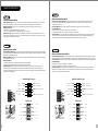
USB 3.0 ConnectionUSB 3.0 Connection
PRESENCE#PRESENCE#
BLACKBLACK
SENSE1_RETURNSENSE1_RETURN
AUD GNDAUD GND
SENSE2_RETURNSENSE2_RETURN
YELLOWYELLOW
BROWNBROWN
REDRED
PORT1 RPORT1 R
PORT2 RPORT2 R
PORT1 LPORT1 L
BLUEBLUE
PORT2 LPORT2 L
SENSE_SENDSENSE_SEND
KEYKEY
PURPLEPURPLE
GREENGREEN
ORANGEORANGE
BLACKBLACK
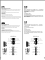
AUDIO HD AUDIO FunctionAUDIO HD AUDIO Function
N.CN.C KEYKEY
RED2RED2
WHITE2WHITE2
GREEN2GREEN2
BLACK2 BLACK2
RED1RED1
WHITE1WHITE1
GREEN1GREEN1
BLACK1 BLACK1
USB F unctionUSB F unction
VCC1
D1-
D1+
GND
NC
VCC1
D1-
D1+
GND
NC
VCC2
D2-
D2+
GND
KEY
VCC2
D2-
D2+
GND
KEY
線材安裝說明
/ 在機殼前方的面板後面,可以找到一些LED與開關線材(POWER Switch….),請參考主機板使用說明書,
並將機殼上的線材正確地連接到主機板上,這些線材通常都會印有標籤在上面,如果沒有的話,請找出機殼前方面板上線材原
本的位置以知道正確的來源。
USB 2.0 連接 / 請參考主機板使用手冊找出主機板上的USB連接孔位
USB 3.0 連接 /
1. 請確認主機板是否支援USB 3.0傳輸介面。
2. 連接USB 3.0傳輸線至主機板上的USB3.0接埠。
音效連接 / 請根據下面的音源接頭圖示與主機板使用手冊來連接音效裝置,請確認主機板上的音效裝置是支援AC' 97音效或是
HD音效(Azalia),裝置錯誤可能會導致主機板音效裝置的毀損,某些主機板的音效裝置不會與下方的圖示完全相同,請參酌主
機板使用手冊以得到正確的安裝資訊
機殼LED連接方式
线材安装说明
/ 在机壳前方的面板后面,可以找到一些LED与开关线材(POWER Switch….),请参考主板使用说明
书,并将机壳上的线材正确地连接到主板上,这些线材通常都会印有标签在上面,如果没有的话,请找出机壳前方面板上线
材原本的位置以知道正确的来源。
USB 2.0 连接 / 请参考主板使用手册找出主板上的USB连接孔位
USB 3.0 连接 /
1.请确认主板是否支持USB 3.0传输接口。
2.连接USB 3.0传输线至主板上的USB3.0接埠。
音效连接 / 请根据下面的音源接头图示与主板使用手册来连接音效装置,请确认主板上的音效装置是支持AC' 97音效或是
HD音效(Azalia),装置错误可能会导致主板音效装置的毁损,某些主板的音效装置不会与下方的图标完全相同,请参酌主板
使用手册以得到正确的安装信息
机壳LED连接方式
藍色線條為尺寸標示,請勿印刷上去!
產品料號
V P 4 0 0 0 S e r i e s C h a s e r A 7 1 說明書 1 3 /0 1 /24 A
產品名稱
印刷項目
子件料號
發稿日期
版本
騎馬釘2 8 8 0 X X X X X
書寫紙
單色 無無
其他特殊處理效果表面處理
2
厚度(g/m )
裝訂方式 材質頁數 印刷色彩
規格樣式
整本
MARKETING CHECK DESIGN
PRODUCT GM
其他特殊處理效果表面處理
2
厚度(g/m )
材質印刷色彩
封面樣式(當封 面 與 內 頁 樣 式不同時尚須填寫)
Peipei
刀模線
125 mm
176 mm
La pagina sta caricando ...
La pagina sta caricando ...
-
 1
1
-
 2
2
-
 3
3
-
 4
4
-
 5
5
-
 6
6
-
 7
7
-
 8
8
-
 9
9
-
 10
10
-
 11
11
-
 12
12
-
 13
13
-
 14
14


Thermaltake Chaser A71 Manuale utente
- Categoria
- Custodie per computer
- Tipo
- Manuale utente
in altre lingue
- English: Thermaltake Chaser A71 User manual
- français: Thermaltake Chaser A71 Manuel utilisateur
- español: Thermaltake Chaser A71 Manual de usuario
- Deutsch: Thermaltake Chaser A71 Benutzerhandbuch
- русский: Thermaltake Chaser A71 Руководство пользователя
- português: Thermaltake Chaser A71 Manual do usuário
- 日本語: Thermaltake Chaser A71 ユーザーマニュアル
- Türkçe: Thermaltake Chaser A71 Kullanım kılavuzu
Documenti correlati
-
Thermaltake Urban S71 Manuale utente
-
Thermaltake VN700M6W2N Scheda dati
-
-
-
-
-
-
Thermaltake Level 10 GTS Manuale utente
-
-
Thermaltake VP300A6W2N Scheda dati
Altri documenti
-
SilverStone LC14S Manuale del proprietario
-
Vantec UGT-CR945 Guida d'installazione
-
Digitus DA-70431 Manuale utente
-
Vantec MRK-310S6 Guida d'installazione
-
Foxconn R10-D1 Manuale utente
-
-
-
Platinum MyDrive Series Operating Instructions Manual
-
Sharkoon M25-W Manuale del proprietario
-
Antec Multimedia Station Elite Guida d'installazione