
1/4
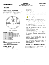
DESCRIZIONE GENERALE
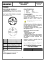
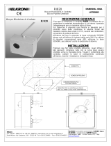
L'SD500/SD500R è lo zoccolo per i sensori a
basso profilo (il mod. SD500R è dotato di uscita
di ripetizione allarme).
La base mod. SD500 è dotata di una morsettiera
(fig.1), mentre il mod. SD500R è provvisto di
due morsettiere (fig.1a).
Morsetto
Descrizione
1
Linea di rilevazione IN (+)
2
Linea di rilevazione IN (-)
3
Linea di rilevazione OUT (-)
4
Linea di rilevazione OUT (+)
5
Non montato sul mod. SD500
Jumper da utilizzare per il ripetitore
di allarme se differente da LR500
6
Non montato su mod. SD500
Uscita ripetizione allarme OUT (-)
7
Non montato su mod. SD500
Uscita ripetizione allarme OUT (+)
JP2
Chiuso: cortocircuita i positivi della linea
rilevazione
Aperto: impostazione di fabbrica
CARATTERISTICHE
Materiale: ABS
Colore: Bianco
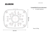
Dimensioni: 90 mm (3.5 in)
COLLEGAMENTI
Tutti i collegamenti elettrici devono essere
conformi agli standard correnti.
Utilizzare cavi di sezione adeguata e di colori
differenti per ridurre il rischio di errori nel
sistema.
Connessioni errate possono creare
errori di sistema.
Utilizzare un cavo schermato: collegare la
schermatura del cavo (una estremità ad anello)
solo alla massa della centrale e collegare la
schermatura attraverso un dispositivo.
La sezione dei conduttori può variare in base
alla lunghezza del cavo.
Si consiglia un conduttore con sezione di 1,5 mm2.
Usare un cavo elettrico che non ecceda i
seguenti limiti:
Resistenza massima = 100Ω
Capacità massima = 2 µF
Il collegamento elettrico deve essere effettuato
rimuovendo circa 10 mm di protezione isolante
dal conduttore principale inserendolo nella
morsettiera.
Controllare il collegamento della linea di
rilevazione (polarità e continuità) prima di
installare i rivelatori sulle basi.
Per il collegamento della base alla linea di
rilevazione utilizzare il diagramma di figura 2 o
2a in base al tipo di applicazione.
USCITA DI RIPETIZIONE ALLARME
(solo mod. SD500R)
I di uscita max
12 mA
Vdi uscita max
12 – 24 V
SD500 – SD500R
Base universale
Universal base
DS80SD4S-001B
LBT80186
ITALIANO
Fig. 1a - SD500R
Fig. 1 - SD500
JP2
JP2

2/4
Fig. 2
Fig. 2A
2
COLLEGAMENTO LINEA LOOP DIGITALE
COLLEGAMENTO LINEA APERTA DIGITALE (senza EOL)
COLLEGAMENTO LINEA CONVENZIONALE
-LA +LA +LB -LB
LINEA RIVELAZIONE
SCHERMO
SCHERMO
-LA +LA
ULTIMO RIVELATORE
EOL
3K3
SCHERMO
SCHERMO
LINEA RIVELAZIONE
-LA +LA +LB -LB
LR500/LR500SI
Rip. Allarme
LR500/LR500SI
Rip. Allarme
SCHERMO
SCHERMO
LR500/LR500SI
Rip. Allarme
LR500/LR500SI
Rip. Allarme
SCHERMO
SCHERMO
-LA +LA
LINEA RIVELAZIONELINEA RIVELAZIONE
Il simbolo di
TERRA sulle basi
non è un
collegamento
elettrico ma solo
un fissaggio
meccanico e di
interconnessione
delle schermature
dei cavi di linea.
Usare viti tipo
Parker 2,9x6mm.
Il resistore di
fine linea (EOL)
deve essere
montato solo
su linee
convenzionali.

3/4
GENERAL DESCRIPTION
The SD500/SD500R are a connection base for
low profile detectors (mod. SD500R is with
alarm repetition output).
The SD500 base is equipped with one terminal
block (fig. 1) instead the mod. SD500R is equipped
with two terminal blocks (fig. 1a).
Terminal
Description
1
Detection circuit IN (+)
2
Detection circuit IN (-)
3
Detection circuit OUT (-)
4
Detection circuit OUT (+)
5
Not mounted on mod. SD500
Jumper to use for alarm repeater
different to LR500
6
Not mounted on mod.SD500
Alarm repetition output OUT (-)
7
Not mounted on mod. SD500
Alarm repetition output OUT (+)
JP2
Closed : electrical connection between
detection circuit positive input and
detection circuit positive output
Open : default setting
FEATURES
Material: ABS
Colour: White
Dimensions: 90 mm (3.5 in).
CONNECTIONS
All electrical connections must be comply to
current standards.
Complying section wires, of different colours,
must be used in order to reduce the risk of
errors on the system.
Incorrect connections create system
faults.
A shielded cable must be used: connect the
shield of the cable (one end in a loop mode) to
the ground in the control panel only and connect
the shield between a device.
The section of leads can vary according to the
length of the detection circuit.
A lead section of 1,5 mm2 is advised.
Don’t use cable that exceed these limit:
Maximum resistance = 100Ω
Maximum capacitance = 2µF
The electrical connection must be performed by
removing approximately 10 mm of insulating
cover from the main lead and insert it on the
terminal block.
Check the wiring of detection circuit (polarity and
continuity) before install the detectors on the
bases.
To connect the connection base to the detection
circuit use the wiring diagram shown in figure 2
or 2a according the application.
ALARM REPETITION OUTPUT
(only mod. SD500R)
I out max
12 mA
Vout max
12 – 24 V
ENGLISH
Fig. 1a - SD500R
Fig. 1 - SD500
JP2
JP2

4/4
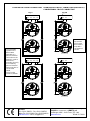
Fig. 2
Fig. 2A
2
LOOP DIGITAL CIRCUIT CONNECTION
OPEN DIGITAL CIRCUIT CONNECTION (without EOL)
CONVENTIONAL CIRCUIT CONNECTION
-LA +LA +LB -LB
DETECTION CIRCUIT
SHIELD
SHIELD
-LA +LA
LAST DETECTOR
EOL
3K3
SHIELD
SHIELD
DETECTION CIRCUIT
-LA +LA +LB -LB
DETECTION CIRCUIT
SHIELD
SHIELD
-LA +LA
LAST DETECTOR
EOL
3K3
SHIELD
SHIELD
DETECTION CIRCUIT
The GROUND
symbol on the
bases isn’t
intended as a
point of electrical
connection to the
ground in a place
of the base
mounting, but only
as a fastening
point of electrical
interconnection of
circuit cable
shield.
Use a Parker
screws 2,9x6mm.
The end of
line resistor
(EOL) must
be mounted
only with a
conventional
circuits.
ELKRON
Tel. +39 011.3986711 - Fax +39 011.3986703
Milano:Tel. +39 02.334491- Fax +39 02.33449213
www.elkron.com – mail to: [email protected]
ELKRON è un marchio commerciale di URMET S.p.A.
ELKRON is a trademark of URMET S.p.A.
Via Bologna, 188/C - 10154 Torino (TO) – Italy
www.urmet.com Made in CHINA
-
 1
1
-
 2
2
-
 3
3
-
 4
4


Elkron R/820 Guida d'installazione
- Tipo
- Guida d'installazione
Documenti correlati
-
 Elkron SP/TEL Guida Rapida
-
 Elkron SD500RL Guida d'installazione
-
 Elkron FDTD500 Guida d'installazione
-
 Elkron FDT400 Guida d'installazione
-
 Elkron FAP548 EVO Guida d'installazione
-
 Elkron FDOT400 Guida d'installazione
-
 Elkron FDO400 Guida d'installazione
-
 Elkron LR500 Guida d'installazione
-
 Elkron R/820 Guida d'installazione
-
 Elkron ZB600 RPT Guida d'installazione


