Zenith H27D55DT Guida d'installazione
- Categoria
- TV LCD
- Tipo
- Guida d'installazione

®
H27D55DT
Installation Guide & Warranty
For qualified electronics servicer/technicians
Table of Contents: page 5
© Copyright 2001 Zenith Electronics Corporation, Commercial Products

WARNING:
TO REDUCE THE RISK OF ELECTRIC SHOCK DO NOT REMOVE COVER (OR BACK). NO USER SERVICEABLE PARTS INSIDE.
REFER SERVICING TO QUALIFIED SERVICE PERSONNEL.
The lightning flash with arrowhead symbol, within an equilateral triangle, is intended to alert the user to the presence of
uninsulated “dangerous voltage” within the product’s enclosure that may be of sufficient magnitude to constitute a risk of
electric shock to persons.
The exclamation point within an equilateral triangle is intended to alert the user to the presence of important operating and
maintenance (servicing) instructions in the literature accompanying the appliance.
WARNING:
TO PREVENT FIRE OR SHOCK HAZARDS, DO NOT EXPOSE THIS PRODUCT TO RAIN OR MOISTURE.
POWER CORD POLARIZATION:
CAUTION: To prevent electric shock, match wide blade of plug to wide slot, fully insert.
ATTENTION: Pour éviter les chocs électriques, introduire la lame la plus large de la fiche dans la borne
correspondante de la prise et pousser jusqu’au fond.
NOTE TO CABLE/TV INSTALLER:
This reminder is provided to call the cable TV system installer’s attention to Article 820-40 of the National Electric Code
(U.S.A.). The code provides guidelines for proper grounding and, in particular, specifies that the cable ground shall be
connected to the grounding system of the building, as close to the point of the cable entry as practical.
REGULATORY INFORMATION:
This equipment has been tested and found to comply with the limits for a Class B digital device, pursuant to Part 15
of the FCC Rules. These limits are designed to provide reasonable protection against harmful interference when the
equipment is operated in a residential installation. This equipment generates, uses and can radiate radio frequency
energy and, if not installed and used in accordance with the instruction manual, may cause harmful interference to radio
communications. However, there is no guarantee that interference will not occur in a particular installation. If this
equipment does cause harmful interference to radio or television reception, which can be determined by turning
the equipment off and on, the user is encouraged to try to correct the interference by one or more of the following
measures:
• Reorient or relocate the receiving antenna.
• Increase the separation between the equipment and receiver.
• Connect the equipment into an outlet on a circuit different from that to which the receiver is connected.
• Consult the dealer or an experienced radio/TV technician for help.
CAUTION:
Do not attempt to modify this product in any way without written authorization from Zenith Electronics Corporation.
Unauthorized modification could void the user’s authority to operate this product.
COMPLIANCE:
The responsible party for this product’s compliance is:
Zenith Electronics Corporation, 2000 Millbrook Drive, Lincolnshire, IL 60069, USA • Phone: 1-847-391-7000.
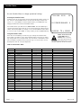
RECORD YOUR MODEL NUMBER
The model and serial number of the TV are located on the
back of the TV cabinet. For future reference, we suggest that
you record these numbers here:
MODEL NO.____________________________________
SERIAL NO.____________________________________
WARNING
RISK OF ELECTRIC SHOCK
DO NOT OPEN
2-WIRE CWARN 3/01
© Copyright 2001 Zenith Electronics Corporation
For Customer Support/Service please call:
1-888-865-3026
www.zenith.com

Important safeguards for you and your new product
Your product has been manufactured and tested with your safety in mind. However, improper use can result in potential
electrical shock or fire hazards. To avoid defeating the safeguards that have been built into your new product, please read
and observe the following safety points when installing and using your new product, and save them for future reference.
Observing the simple precautions discussed in this operating guide can help you get many years of enjoyment and safe
operation that are built into your new product.
This product complies with all applicable U.S. Federal safety requirements, and those of the Canadian Standards Association.
1. Read Instructions
All the safety and operating instructions should be read
before the product is operated.
2. Follow Instructions
All operating and use instructions should be followed.
3. Retain Instructions
The safety and operating instructions should be retained
for future reference.
4. Heed Warnings
All warnings on the product and in the operating instruc-
tions should be adhered to.
5. Cleaning
Unplug this product from the wall outlet before cleaning.
Do not use liquid cleaners or aerosol cleaners. Use a damp
cloth for cleaning.
6. Water and Moisture
Do not use this product near water for example, near a
bath tub, wash bowl, kitchen sink, or laundry tub, in a
wet basement, or near a swimming pool.
7. Accessories, Carts, and Stands
Do not place this product on a slippery or tilted surface,
or on an unstable cart, stand, tripod, bracket, or table.
The product may slide or fall, causing serious injury to a
child or adult, and serious damage to the product. Use
only with a cart, stand, tripod, bracket, or table recom-
mended by the manufacturer, or sold with the product.
Any mounting of the product should follow the manufac-
turer’s instructions, and should use a mounting accessory
recommended by the manufacturer.
8. Transporting Product
A product and cart combination should be moved with
care. Quick stops, excessive force, and uneven surfaces
may cause the product and cart combination to overturn.
9. Attachments
Do not use attachments not recommended by the product
manufacturer as they may cause hazards.
10. Ventilation
Slots and openings in the cabinet are provided for
ventilation and to ensure reliable operation of the product
and to protect it from overheating, and these openings
must not be blocked or covered. The openings should
never be blocked by placing the product on a bed, sofa,
rug, or other similar surface. This product should not be
placed in a built-in installation such as a bookcase or rack
unless proper ventilation is provided or the manufacturer’s
instructions have been adhered to.
11. Power Sources
This product should be operated only from the type of
power source indicated on the marking label. If you are
not sure of the type of power supply to your home,
consult your product dealer or local power company. For
products intended to operate from battery power, or other
sources, refer to the operating instructions.
12. Power Cord Polarization
This product is equipped with a polarized
alternating-current power plug (a plug having one blade
wider than the other). This plug will fit into the power
outlet only one way. This is a safety feature. If you are
unable to insert the plug fully into the outlet, try
reversing the plug. If the plug should still fail to fit,
contact your electrician to replace your obsolete outlet.
Do not defeat the safety purpose of the polarized plug.
13. Power Cord Protection
Power-supply cords should be routed so that they are not
likely to be walked on or pinched by items placed upon or
against them, paying particular attention to cords at
plugs, convenience receptacles, and the point where they
exit from the product.
PAGE 3
IMPORTANT SAFETY INSTRUCTIONS
PORTABLE CART WARNING
(Continued on next page)
206-3706 2-WR-POLZ

(Continued from previous page)
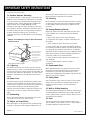
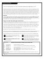
14. Outdoor Antenna Grounding
If an outside antenna or cable system is connected to the
product, be sure the antenna or cable system is grounded
so as to provide some protection against voltage surges
and built-up static charges. Article 810 of the National
Electrical Code (U.S.A.), ANSI/ NFPA 70 provides
information with regard to proper grounding of the mast
and supporting structure, grounding of the lead-in wire to
an antenna discharge unit, size of grounding conductors,
location of antenna-discharge unit, connection to
grounding electrodes, and requirements for the grounding
electrode.
15. Lightning
For added protection for this product (receiver) during a
lightning storm, or when it is left unattended and unused
for long periods of time, unplug it from the wall outlet and
disconnect the antenna or cable system. This will prevent
damage to the product due to lightning and power-line
surges.
16. Power Lines
An outside antenna system should not be located in the
vicinity of overhead power lines or other electric light or
power circuits, or where it can fall into such power lines or
circuits. When installing an outside antenna system,
extreme care should be taken to keep from touching such
power lines or circuits as contact with them might be
fatal.
17. Overloading
Do not overload wall outlets and extension cords as this
can result in a risk of fire or electric shock.
18. Object and Liquid Entry
Never push objects of any kind into this product through
openings as they may touch dangerous voltage points or
short-out parts that could result in a fire or electric shock.
Never spill liquid of any kind on the product.
19. Servicing
Do not attempt to service this product yourself as opening
or removing covers may expose you to dangerous voltage
or other hazards. Refer all servicing to qualified service
personnel.
20. Damage Requiring Service
Unplug this product from the wall outlet and refer servic-
ing to qualified service personnel under the following
conditions:
a. If the power-supply cord or plug is damaged.
b. If liquid has been spilled, or objects have fallen into
the product.
c. If the product has been exposed to rain or water.
d. If the product does not operate normally by following
the operating instructions. Adjust only those controls that
are covered by the operating instructions as an improper
adjustment of other controls may result in damage and will
often require extensive work by a qualified technician to
restore the product to its normal operation.
e. If the product has been dropped or the cabinet has
been damaged.
f. If the product exhibits a distinct change in
performance.
21. Replacement Parts
When replacement parts are required, be sure the service
technician has used replacement parts specified by the
manufacturer or have the same characteristics as the
original part. Unauthorized substitutions may result in fire,
electric shock, or other hazards.
22. Safety Check
Upon completion of any service or repairs to this product,
ask the service technician to perform safety checks to
determine that the product is in proper operating
condition.
23. Wall or Ceiling Mounting
The product should be mounted to a wall or ceiling only as
recommended by the manufacturer. The product may slide
or fall, causing serious injury to a child or adult, and seri-
ous damage to the product.
24. Heat
The product should be situated away from heat sources
such as radiators, heat registers, stoves, or other products
(including amplifiers) that produce heat.
PAGE 4
206-3706 2-WR-POLZ
IMPORTANT SAFETY INSTRUCTIONS
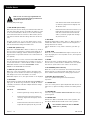
Antenna Lead in Wire
Antenna Discharge Unit
(NEC Section 810-20)
Grounding Conductor
(NEC Section 810-21)
Ground Clamps
Power Service Grounding
Electrode System (NEC
Art 250, Part H)
Ground Clamp
Electric Service
Equipment
Example of Grounding According to National Electrical
Code Instructions
NEC - National Electrical Code

206-3706
PAGE 5
Table of Contents
Installation Guide - Operational information and set up instructions provided for qualified electronics
servicer/technicians to configure or adjust the features of this TV.
Installer/Service Information
Note: This information is provided for technically qualified service personnel only.
Settings should not be changed by the average user!
Note: See the separately supplied user Operating Guide and Warranty for all other available information.
Safety Warnings . . . . . . . . . . . . . . . . . 2
Important Safety Information . . . . . 3 - 4
Table of Contents . . . . . . . . . . . . . . . . 5
LP702 Optional Installer’s Remote Control 6
Auto Program . . . . . . . . . . . . . . . . . . 7
Picture/Sound Source Selection . . . . . . 8
Source Menu . . . . . . . . . . . . . . . . . . . 9
Parental Control Menu . . . . . . . . 10 - 11
Setting Preset Channel Labels . . . . . . . 12
Creating Your Own Channel Labels . . . . 13
Installer Menus . . . . . . . . . . 14 - 15 - 16
LT2000 Quickset II Clone Programmer
Operation . . . . . . . . . . . 17 - 18 - 19
Warranty . . . . . . . . . . . . . . Back Cover
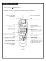
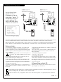
captions
L-audio-Rvideo
S-video
volume
channel
power
menu
volume
channel
power
Typical TV
Front Panel
1
2
A
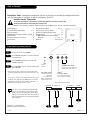
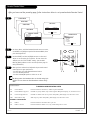
Left/Right Audio (Input)
Connects the audio output from
external stereo audio devices.
CamPort
TM
Front Video (Input)
Connects the video output
from external video devices.
Typical Front Panel Controls
To turn the TV on press POWER.
Press VOLUME Up/Down to increase/decrease
the sound level.
Press CHANNEL Up/Down to tune to next
available channel.
Press CAPTIONS to turn selected caption/text
option On/Off.
1
2
3
A
There are three jacks on the front of the TV that make
connecting Audio/Video devices like camcorders very sim-
ple.
To use the front jacks as the signal source, simply plug a
composite video cable into the VIDEO jack. The TV will
automatically change its source setting to CamPort
TM
, as
indicated on the channel selection screen.
Auto Sense source connections override all other
sources. The front Video In and S-Video In jacks
are Auto Sense source connections. If you have a
device(s) connected to these jacks, you will not be
able to change channels until you have disconnect-
ed the device(s).
Front Panel Operation/Controls
CamPort
TM
is a trademark of
Zenith Electronics Corporation
3
Front S-Video (Input)
Connects the S-Video
output from
an external S-Video
device. (Use with Front
L-Audio-R input jacks.)
LED
Power on
indicator.

206-3706
PAGE 6
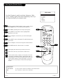
LP702 Optional Installer’s Remote
TIMER
CH PREVIEW
ENTER
1
2
3
4
5
6
7
8
9
0
POWER
FLSHBK
MUTE
VOL
UME
CHANNEL
TV/FM
CC
MENU
ALARM
ADJ
ADJ
SELECT
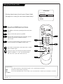
FLASHBK (FLASHBACK)
Returns to the last channel viewed.
POWER
Turns TV On or Off
.
CHANNEL (UP/DOWN)
Selects next available channel and the
video channel.
MUTE
Turns sound Off and On, while the picture
remains.
ENTER
Press to view the Channel/Time display or
to remove any on-screen display or menu.
remote control part number
LP702
124-213-04
TIMER
Press repeatedly to select preset TV turn-
off time from 10 minutes up to 4-hours.
Sets AM or PM in the Clock/Alarm menus.
VOLUME (LEFT/RIGHT)
Adjusts the sound level.
CC (CLOSED CAPTIONING)
Direct access to closed captions.
Press ENTER to exit.
A quick list of the keys on the optional LP702 installer’s remote and what they do
ALARM
Press to go to the Alarm menu. Set a time
for the TV to turn itself on.
MENU/SELECT/ADJ (ADJUST)
Adjusts on-screen menus and options.
Press MENU repeatedly to scroll through
menus. Use SELECT to choose an option
and ADJ (adjust) Left/Right to change
the selected option.
CHANNEL PREVIEW
Gives installer access to the Guest’s
menus. Displays the available TV channels
and hotel guest’s Parental Control menu
(if active). Selects the Video source. (Use
the Audio/Video jacks on the back of the
TV as the source of the picture and
sound.)
TV/FM
Selects TV or Radio operation on TVs
equipped with FM radio.
NUMBER KEYPAD
Used to key-in numbers and select chan-
nels directly: key-in channel numbers and
press ENTER to go to the new channel
.
Note: This remote is NO
T supplied with the TV.

206-3706
PAGE 7
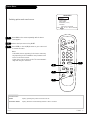
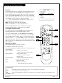
Auto Program (Channel Search)
Use Auto Program to specify over-the-air Antenna or Cable
Service incoming signal source and automatically store all of
the channels found by the channel search
With the optional LP702 Installer’s remote control in hand,
press POWER to turn on the Entertainment Machine.
Press MENU repeatedly until the Setup menu appears.
Using SELECT on the remote control, highlight Auto
Program on the screen.
Press the Right or Left arrow to go to the Auto Program
menu.
Using SELECT, choose either Cable TV or Off-Air Antenna on
your screen.
Press the Right or Left arrow to begin the Channel Search.
Press ENTER when the channel search is complete.
1
2
3
4
5
6
7
AUTO PROGRAM
ADD/DEL/BLNK
CH. LABELS
CLOCK SET
TIMER
CAPTIONS
LANGUAGE
TO PROGRAM
SETUP MENU
Mini glossary
OFF-AIR-ANTENNA If only over-the-air channels are available, select Off-Air-Antenna.
CABLE If you subscribe to a cable service, select Cable.
Auto Program finds channels being received by the TV tuner.
Cable will not work unless you subscribe to a cable service.
Once the channel search is complete, use the features on the fol-
lowing pages to: Add/delete channels, Include channel labels, so
that they appear on the channel/time/audio display. Choose from
the preset label selections or make custom labels. Use your own
names to more easily identify the station/network providing the
program.
TIMER
CH PREVIEW
ENTER
1
2
3
4
5
6
7
8
9
0
POWER
FLSHBK
MUTE
VOL
UME
CHANNEL
TV/FM
CC
MENU
ALARM
ADJ
ADJ
SELECT
2
7
3/5
4/6
1

206-3706
PAGE 8
Picture/Sound Source Selection
AUDIO/VIDEO OUT
VIDEO
R -AUDIO-L
OUT
S-VIDEO
R -AUDIO-L
AUDIO/VIDEO OUT
R -AUDIO-L
AUDIO/VIDEO OUT
VIDEO
R -AUDIO-L
COMPONENT VIDEO
R -AUDIO-L
Video In
L- Audio - R
Camcorder
VCR
S-Video
Audio/Video
DVD
Component Video
S-Video
Typical
TV Back
S-Video In
M.P.I.
R Audio In L
S-Video Out
Antenna
Cable
Component Video Input
R Audio In L
R Audio L
Video In
Y
Pr
Pb
Matrix Out
Pb
Y Pr
VIDEO
Hook up a device to front Video/Audio In, to use this Auto
Sense source, disconnect when finished.
To access other available sources press TV/VCR SOURCE repeat-
edly to show selectable sources on the screen. Or, use the
Source menu, or use Channel Up/Down to select AUX input.
Note: The rear Video/Audio In jacks can also be selected by
keying in 999 on the remote number keypad.
Note: The Installer, by changing options in the service menu, can change the default setup
and determine what source connections are available.
• Auto Source Sense connections override other source inputs. Default is front Video In.
• Pressing TV/VCR SOURCE repeatedly on the remote, shows what sources are available.
• The Source menu shows what sources are available using the Source menu.
1
2
Auto Sense source connections override all other sources. The front
Video In jack is a Auto Sense source connection. If you have a device
connected to this jack, you will not be able to change channels until
you have disconnected the device.
Typical Accessory
Equipment
Front/Rear
Connection Panels
Connectable Sources
See pages 6-14 in Operating Guide
Antenna/Cable
Camport (Front Video input)
Front S-Video
Aux Video (Rear Video inputs)
Rear S-Video
Component Video

206-3602
PAGE 9
TIMER
CH PREVIEW
ENTER
1
2
3
4
5
6
7
8
9
0
POWER
FLSHBK
MUTE
VOL
UME
CHANNEL
TV/FM
CC
MENU
ALARM
ADJ
ADJ
SELECT
Source Menu
Selecting picture and sound sources
Press MENU on the remote repeatedly until the Source
menu appears.
Choose the input source using SELECT.
Press ENTER, or the Left/Right arrow to go to source and
to remove the menu.
Notes:
• Selectable sources appearing in the Source menu may
vary depending on the installation setup for Auto Sense
sources in the Service menu.
• Auto Sense sources appear on the TV screen automati-
cally when they are connected.
1
2
3
2
ANTENNA/CABLE
CAMPORT
FRONT S-VIDEO
REAR S-VIDEO
COMPONENT (Y Pb Pr)
AUX VIDEO
SOURCE MENU
PRESS SELECT TO CHANGE
PRESS ENTER OR
< >
KEYS TO ACTIVATE
3
1
3
Mini glossary
SOURCE Input(s) providing the picture and sound to the TV.
AUTO SENSE SOURCE Input(s) which the TV automatically switches to when connected.

PAGE 10
206-3706
Parental Control Menu
Mini glossary
MOTION PICTURE ASSOCIATION OF AMERICA (MPAA) RATING SYSTEM
G General Audiences Content not offensive to most viewers.
PG Parental Guidance Content is such that parents may not want their children to view the program.
Suggested
PG-13 Parental Guidance Program is inappropriate for preteens, with a greater degree of offensive material
Suggested than a PG rated program.
R Restricted viewing Not for children under age 17. Strong elements of sex and/or violence.
NC-17 Restricted Viewing Not for children under age 17 under any circumstances. Strong sexual content.
X Hard Core Films Same as NC-17 rating.
Note: Zenith Electronics Corporation is not liable for any program content that appears when using this rating system; as always, user
discretion is advised.
Overview
To insure complete coverage for all TV programs, (movies and regular TV shows) choose a rating for MPAA, from the selec-
tions below AND choose ratings from the TV Parental Guidelines Rating System on the next page, using the Age Block
option for General Audiences, and for Children. In addition to those, you may wish to add additional restrictions from the
Content Block menu. See the Parental Control menu, and submenus example on the next page.
Things to Consider before Setting Up Parental Control
Determine which rating you consider acceptable to the viewer. (For example, if you choose TV-PG, all more restrictive rat-
ings will be automatically blocked; the viewer will not be able to see: TV-PG, TV-14, or TV-MA rated programming.)
Do you want to block the auxiliary video source entirely? (Blocks the signal sent by the equipment, such as a VCR, con-
nected to the TV Audio/Video input jacks; in the Aux. Block option.) Or leave unblocked, then choose allowable ratings.
Block program “Content” based on individual parameters such as: Strong Dialog, Bad Language, Sex Scenes, Violence
Scenes, or Fantasy Violence Scenes; in the Content Blk option.
How many hours do you want Parental Control to be active? You can set the Hours option for up to 99 hours.
Select a secret password; in the Set Password option. Use the number keys on the remote. Don’t forget the password, it is
the only way you can access the Parental Control menu and change rating selections, or turn Parental Control off.
Do you want Parental Control to be active all the time? If not, you can turn it on or off; with the Lock On/Off option.
If used, this optional feature can “block” undesirable programming from appearing on the TV.
You can set different Parental Control viewing restric-
tions for general audiences and for children - - both can
be active at the same time
.
Simply specifying one content block such as Sex Scenes,
will not automatically block another content in the pro-
grams from appearing.
Even if you choose to leave the Aux inputs unblocked, the
ratings you specify will automatically restrict the program-
ming that appears from the video sources.
You cannot disable Parental Control by disconnecting the TV
from power. Block hours will automatically reset to the origi-
nal block time setting specified if power is disconnected.
Parental Control offers the user a wide variety of options and settings that restrict or “block” the programming that can
appear on the TV. Parental control allows the user the capability of defining which program rating they consider accept-
able, to the younger or more sensitive viewer. It can be preset and turned either on or off by the user who specifies the
secret 4-number code, the password. The number of hours blocked are specified. General audience and children viewer
blocks should both be programmed into the TV’s memory. Viewer ratings are specified for both TV and the motion picture
industry; both rating systems should be used, for complete coverage. The ratings are based on the ages of children.

PAGE 11
206-4543
TIMER
CH PREVIEW
MENU
ALARM
ADJ
ADJ
SELECT
Parental Control Menu
Mini glossary
TV PARENTAL GUIDELINE RATING SYSTEM
TV-G General Audience Considered suitable for all audiences; children may watch unattended.
TV-PG Parental Guidance Suggested Unsuitable for younger children, may contain: Suggestive Dialog, Bad Language, Sex, and Violence Scenes.
TV-14 Parents Strongly Cautioned Unsuitable for children under 14, may contain: Strong Dialog, Bad Language, Sex, and Violence Scenes.
TV-MA Mature Audience Only Adults only, may contain: Strong Dialog, Bad Language, Sex, and Violence Scenes.
CHILDREN’S CLASSIFICATIONS
TV-Y Children Considered suitable for all children under 7 years old.
TV-Y7 Children 7 and over Considered suitable for children over 7, may contain Fantasy Violence Scenes.
As shown above, with the Parental Control menu on-screen,
use SELECT to highlight an option like Content Block, then
press the Right arrow.
Use the SELECT, and the Left/Right arrows to select and
adjust or set the rating for an option. For Sex Scenes for
example, use the “From TV-PG” setting. (See the Mini
Glossary, Ratings Charts on this and the previous page for
rating definitions.)
After you have selected and adjusted the parental control
menu options to your preferences:
- Set the hours you want Parental Control active.
- Set a 4-number password.
- Set the Lock On/Off option to either on or off.
No Rating means the broadcast does not include rating infor-
mation. You can choose to block broadcasts without rating
data.
After you have read the preceding page, follow instructions below to set up and activate Parental Control
SOURCE MENU
SETUP MENU
AUDIO MENU
DIALOG
LANGUAGE
SEX SCENES
VIOLENCE
F VIOLENCE
NO RATING
TO BLOCK
GENERAL
CHILDREN
AGE BLOCK
UNBLOCKED
CONTENT BLOCK
TO BLOCK
AUX SOURCES
MPAA RATING
AGE BLOCK
CONTENT BLK
SET HOURS
SET PASSWORD
LOCK ON OFF
PARENTAL CONTROL
VIDEO MENU
PRESS CC TO RETURN
PRESS CC TO RETURN
2/3
2/3
1
2
3
4

PAGE 12
206-3706
Setting Preset Channel Labels
Selecting channel names from the preset Channel Labels
(See page 24 to create your own custom channel labels)
Using either the NUMBER keypad or the Channel
Up/Down arrows on the remote, select a channel.
Press MENU on the remote repeatedly until the Setup menu
appears.
Choose the Ch Labels option using SELECT.
Pressing either the Right/Left arrow repeatedly, pick the
label you want from the available selections;
such as A & E.
To continue channel labeling, select another channel or
if you are finished, press ENTER to remove menu.
1
2
3
4
AUTO PROGRAM
ADD/DEL/BLNK
CH. LABELS
CLOCK SET
TIMER
CAPTIONS
LANGUAGE
CH 32 ABC
SETUP MENU
Mini glossary
- - - - The 4 dashes will allow a channel label to appear; if one is provided by the broadcaster.
NONE Prevents any channel label from appearing.
LAB 1, Are the 20 programmable labels. These 20 labels can be customized with 5 characters spaces available for each label.
thru LAB 20,
Some channels already provide a channel label which is included
with the broadcast signal.
Labeling the channels helps identify which familiar nationwide
channels are available. i.e., A & E - Arts and Entertainment,
CNN - News, ESPN - Sports, HBO - Movies and so on...
5
TIMER
CH PREVIEW
ENTER
1
2
3
4
5
6
7
8
9
0
POWER
FLSHBK
MUTE
VOL
UME
CHANNEL
TV/FM
CC
MENU
ALARM
ADJ
ADJ
SELECT
2
4
5
1
3
1

PAGE 13
206-3492-O
Creating Your Own Channel Labels
AUTO PROGRAM
ADD/DEL/BLNK
CH. LABELS
CLOCK SET
TIMER
CAPTIONS
LANGUAGE
CH 32 MYLAB
SETUP MENU
PRESS VOL UP/DN TO SELECT CHAR
Mini glossary
- - - - The 4 dashes will allow a channel label to appear; if one is provided by the broadcaster.
NONE Prevents any channel label from appearing.
LAB 1, Are the 20 programmable labels. They can be customized for your needs with 5 characters spaces available on each
thru LAB 20, label.
TIMER
CH PREVIEW
ENTER
1
2
3
4
5
6
7
8
9
0
POWER
FLSHBK
MUTE
VOL
UME
CHANNEL
TV/FM
CC
MENU
ALARM
ADJ
ADJ
SELECT
1
1
1
1
Overview
Channel Labels help the user identify the channel/network on the TV.
In the Setup menu with the CH LABELS option highlighted, use the
Adjust Left/Right arrow to scroll through the available channel labels,
such as, A & E, AMC, ESPN, HBO, etc. These are a series of alphabeti-
cally organized preset labels from which you can choose the more com-
mon networks. Use any of these or create custom labels.
- - - - , The 4 dashes will allow a channel label to appear; if one is
provided by XDS. (Extended data service)
NONE, prevents any channel label from appearing.
LAB 1, thru LAB 20, are the 20 programmable labels.
The 20 programmable labels can be customized for your needs.
Each programmable label has 5 characters spaces available.
To Program a Channel Label
First select a channel using the NUMBER keypad and ENTER or the
Channel Up/Down arrow, on the Installer’s remote control.
(To select a deleted channel, use the NUMBER keypad and ENTER.)
To program a channel label, go to the Setup menu, select CH LABELS.
Press the Right/Left ADJ (Adjust) arrow to scroll the available preset
labels. Scroll past - - - -, scroll past NONE, to go to the first program-
mable label slot, LAB 1. Notice that the label appears with the title
LAB 1, and is also on a dark background; which will distinguish it from
the preset labels.
Operating the Menu
Use Volume Up/Down to select the first letter.
Press MUTE to clear the label if necessary.
Use Channel Up/Down to change the character to one of the 255 char-
acters available.
Adjust Left/Right Switches to the next label.
- - moves to the next or previous label.
Volume Up/Down Selects character spaces
- - moves to the next or previous
character space.
Channel Up/Down Scrolls through the available characters.
ENTER Accepts the channel label and
removes the menu.
MUTE Removes current label,
- - if first character space is selected.
1
1

PAGE 14
206-3492-O
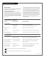
Item Description Range Fact. Set Recommended Setting
00 FACT MENU 0 - 1 0 Leave default set 0
01 PRESET PX 0 - 1 1
02 PRESET AX 0 - 1 1
03 POWER MANAGE 0 - 7 0
04 VERT POS 0 - 30 15 (Approx.)
05 HORZ POS 0 - 45 25 (Approx.)
06 BAND/AFC 0 - 7 0
07 MIN VOLUME 0 - 63 0
08 MAX VOLUME 0 - 63 63
09 AC ON 0 - 1 0
10 STRT CHANNEL 0 - 255 255
11 STRT VOLUME 0 - 63, 255 255
12 CHAN LOCK 0 - 1 0
13 GHOST CH. 0 - 1 0
14 SCAN MODE 0 - 3 0 Leave default set 0
15 TEXT MODE 0 - 1 1
16 SLEEP TIMER 0 - 1 1
17 ALARM 0 - 1 1
18 CH. OVER RIDE 0 - 1 1
19 OLD OCV 0 - 1 0
20 CAPTION LOCK 0 - 1 0
21 FUNCTION PRE 0 - 1 0
22 FEATURE LEVEL 0 - 1 1 Zen 1/0 P Lbl Leave default set 1 (1 Zen 1)
Installer Menus
Use the Installer Menus to change operational settings
221-1518 01.20 02
03 POWER MANAGE 0
XX/XX/XX TE = 1111111
Accessing the Installer’s Menu
Installer’s menus can be accessed by using the optional LP702 installer’s remote con-
trol. Just press and hold MENU (about 8 seconds) until the display changes, then
press 9, 8, 7, 6, then ENTER. To exit the Installer’s Menu, press ENTER again. Any
changes you make will be stored in nonvolatile memory.
The Installer’s Menu opens with item 03, POWER MANAGE. Press the SELECT key to
sequence through the various items. Or, access an item directly by entering the line
number, then pressing MENU. For example, to access the Start Channel option which
is on line 11, press 11, then MENU. To change a setting use the Left/Right ADJ keys.
Using the Installer’s Menu
Items 00-22 are immediately accessible only upon entering the Installer’s Menu.
Their numbers, descriptions, ranges, factory default settings, and a place for listing
any changes made on-site are given below. A second section of the Installer’s Menu
that is intended for qualified service technicians only is not shown (items 23-124).
Normally these items do not require adjustment.
Items in the Installer’s Menu:
Installer should leave item
00 FACT MENU set to 0
(default). Items 23-124 are
service-type adjustments and
only qualified technicians having special-
ized test equipment should access them.

PAGE 15
206-3492-O
Installer Menus
00 FACT MENU (Factory Menu)
Used to access and customize Service Menu settings using the
installer type remote.
01 PRESET PX (Preset Picture)*
Saves your custom video settings (color, tint, contrast, and
brightness) in nonvolatile memory (not affected by power loss).
Memory status is indicated by a 1 for “custom settings already
stored,” or 0 for “custom settings have not been stored.”
Make all custom video settings before you access the Installer’s
Menu: and PRESET PX. When you use the ADJUST keys to toggle
from 0 - 1, any changes in the video settings will be stored sure
they are correct! These settings become the PRESET values for the
PICTURE PREF option of the Video Menu. (For more information
refer to the Video Menu section of this manual.)
02 PRESET AX (Preset Audio)
Saves your custom audio settings in nonvolatile memory (not
affected by power loss). Memory status is indicated by a 0 for
“custom settings already stored,” or 1 for “custom settings have
not been stored.”
Make all custom audio settings before you access the Installer’s
Menu and PRESET AX. When you use the ADJUST keys to toggle
from 0 - 1, any changes in the audio settings will be stored be
sure they are correct! These settings become the PRESET values
for the Audio Menu. (For more information refer to the Audio
Menu section of this manual.)
03 POWER MANAGE (Power Management)
The POWER MANAGE function is for saving energy. When set to 0,
Power Manage is OFF. Settings range from 0 - 7, with 1 - 7 repre-
senting the hours that the TV will remain on, unless there has
been activity from either the control panel or remote.
04 VERT POS (Vertical Position)*
Moves displays vertically on the screen. Use the Left/Right
ADJUST arrows. Typical value is 15. Black bars top and bottom
define the active screen area.
05 HORZ POS (Horizontal Position)*
Moves displays horizontally on the screen. Use the ADJUST keys.
Typical value is 34. Black bars top and bottom define the active
screen area.
06 BAND/AFC (Band/Automatic Frequency Control)
There are 8 possible settings for this option:
0 = Broadcast Fixed 4 = Broadcast AFC
5 = CATV Fixed 1 = CATV AFC
6 = HRC Fixed 2 = HRC AFC
7 = ICC Fixed 3 = ICC AFC
Channels are accessed faster when fixed modes are used. The AFC
(search modes) should only be used when some channels are not
on nominal frequencies.
NOTE: BAND is automatically set by AUTO PROGRAM.
If some channels were not found by AUTO PROGRAM, select the
appropriate AFC setting here and add the channels using the
ADD/DEL option in the Setup Menu.
07 MIN VOLUME (Minimum Volume)
This function determines the minimum volume level allowable
with the VOLUME (VOL) Up/Down control. In this way, for exam-
ple, someone cannot set the volume too low to hear. The range is
from 0 to 63—change values with ADJUST . The factory default is
0, which provides full range of volume control. It may be best to
set the same value on every TV. NOTE: The minimum volume level
cannot have a value setting higher than in the MAX VOLUME level
(described below).
08 MAX VOLUME (Maximum Volume)
This function determines the maximum volume level allowable
with the VOLUME VOL Up/Down control. In this way, for example,
someone cannot set the volume level high enough to disturb oth-
ers. The range is 0 to 63, with 63 as the default which gives the
user the full range of volume control. Change values with ADJUST
keys. It may be best to set the same value on every TV. NOTE: The
maximum volume level cannot have a value setting lower than the
MIN VOLUME level (described above).
09 AC ON (AC Power Switchable)
Allows the TV to turn ON just by applying AC power. Pressing the
ON button is not necessary. This is desirable when the TV is
plugged into a cable box or a power outlet controlled by a wall
switch. Use ADJUST to select 0 or 1, where 0 is the default is
OFF, and 1 is ON.
NOTE: When set to 1 (ON), the TV does not respond to ON/OFF
commands from either the remote or the control panel, and the
SLEEP TIMER is also nonfunctional.
10 STRT CHANNEL (Start Channel)
When active, this function allows you to determine the initial
channel number when the TV is turned ON. This feature is useful
for an in-house information channel, since the TV would always
select that channel when it is turned on. Setting this to 255
causes the last channel viewed when TV was turned off to be the
tuned to channel when the TV is turned on again.
The range of values is 0 - 255. Use (adjust) keys to choose num-
bers that determine the start channel.
Continued on next page.

PAGE 16
206-3492-O
Continued from previous page.
11 STRT VOLUME (Start Volume)
When active, this function allows you to determine the initial vol-
ume level setting when the TV is turned ON. This feature is useful
for an in-house information channel, since the TV would always
select that channel when it is turned on. When inactive, the vol-
ume level and channel retain the settings when the set was last
used.
The range of values is 0 - 63, 255. Use (adjust) keys to choose:
(1) With number 255 the feature is inactive. (2) Set the volume
level as desired before exiting the installer menu.
12 CHAN LOCK (Channel Lock)
When set to 1 the CHAN LOCK is ideal if a cable box (or similar) is
the sole source for programming—and the TV must always be on
the same channel. Changing channels with Channel Up/Down or
keypad numbers is impossible. Channel Lock is inactive when set
to 0 (default).
Generally, this feature is used in connection with START CHANNEL
(line 11) where the start channel may, for example, be set to 3 or
4. If the start channel is 3 then the TV will remain on channel 3.
NOTE: When channel lock is active AUTO PROGRAM and CH.
ADD/DEL in the SETUP MENU are not active.
13 GHOST CH. (Ghost Channel)
When set to 1, the current channel number is displayed in the
upper right corner of the CRT. The number moves slightly to pre-
vent damage to the screen. The default is “0” or OFF.
NOTE: When captions are on, the “ghost channel” is not displayed.
14 SCAN MODE
Allows variation in setting the On/Off with Channel UP/DOWN. You
may opt for TV channels only; TV channels + Off/ON; TV channels
+ FM radio; TV channels + FM radio + Off/On with these settings
for Scan Mode:
Scan mode Characteristics
0 Channel up/down keys change channels only.
1 Channel down below the lowest channel (or
channel up higher than the highest) and TV
turns off.
2 Channel down below the lowest channel (or up
higher than the highest) and TV goes to FM
radio. Channel down below lowest FM station
(or Channel up higher than the highest) and
TV channels return
3 Channel down below the lowest channel (or up
higher than the highest) and TV goes to FM
radio. Press channel down below lowest FM
station (or Channel up higher than the high
est) and TV turns off.
15 TEXT MODE
Determines whether TEXT 1, TEXT 2, TEXT 3, or TEXT 4 decoding is
enabled when TEXT is turned on (either from the Setup Menu or
directly with CC on the remote).
TIP: Set Text Mode to 1 only if text is offered in your video sys-
tem.
16 SLEEP TIMER
When set to 1, the SLEEP TIMER feature may be used (but no mes-
sage is displayed prior to turn-off). When set to 0, the sleep timer
is not available.
17 ALARM
Gives you the option of making the alarm function available to
the user. Set to 1, alarm function is available. Set to 0 to disable
this function. (Clock must be set in order to use the alarm.)
18 CH. OVERRIDE (Channel Override)
When set to 1, the user is allowed to select channels with either
Channel up/down or by direct keypad entry. When set to 0, only
those channels that are entered for scanning may be selected.
19. OLD OCV (On Command Video
TM
)
Set to 1 for operation with systems from On Command
Corporation.
20. CAPTION LOCK
Set to 1 to restore previous caption On/Off state after TV turns off
when set to 0, captions are always off when TV is initially turned
on.
21. FUNCTION PRE
Set to 0 to suppress CHANNEL PREVIEW FUNCTION with some pay
per view systems.
22. FEATURE LEVEL
Default set to ZEN 1 for Zenith IR remote control operation. Set
O, P LBL for Zenith Private Label IR remote control operation.
Installer Menus
Note: Installer should leave item 22 FEATURE
LEVEL set to 1 (default).
Items 23-124 are service-type adjustments and
only qualified technicians having specialized test
equipment should access them.

PAGE 17
206-3492-O
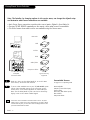
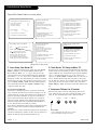
LT2000 QuickSet Programmer
A slow flashing green light indicates there is a problem with the communications between the TV and the programmer. In this case,
check for a damaged cable, poor contacts, or other connection troubles.
If the status indicator is red, the programmer batteries are low and should be replaced. Use 4 good-quality alkaline AA batteries.
Use the Zenith LT2000
QuickSet II “Clone”
Programmer to copy the
setup from a “master” TV
then quickly transfer the
setup to duplicate TVs -
must be the same model
number as the master TV
TV back
VIDEO
R -AUDIO- L
LOOP OUT - S-VHS - IN
ANTENNA
CABLE
R- AUDIO- L
S-VIDEO
INPUT
COMPUTER
AUDIO INPUT
RIGHT
LEFT
AUX
INPUT
M.P.I.
RF coaxial wire
(75ohm)
Antenna
QuickSet II Programmer
LT2000
®
TV back
VIDEO
R -AUDIO- L
LOOP OUT - S-VHS - IN
ANTENNA
CABLE
R- AUDIO- L
S-VIDEO
INPUT
COMPUTER
AUDIO INPUT
RIGHT
LEFT
AUX
INPUT
M.P.I.
RF coaxial wire
(75ohm)
Antenna
QuickSet II Programmer
LT2000
®
Clone
Clone
Learn Master TV
Typical MPI Connections
Teach Other TV
Typical MPI Connections
The optional QuickSet II Clone Programmer (LT2000) allows custom setup and programming information to be quickly copied from a mas-
ter TV into multiple identical television sets. Once learned from the master, setup data is retained in the LT2000 for future use.
When using the LT2000, cloning operations will go easier if the TV set is connected to a good quality signal and operating with a stable
picture displayed. To operate the LT2000, use the indicated keys on the LP702 remote, or the front panel keys on the TV receiver.
THE CLONE HAS CONTROL OF THE TV
THE CLONE IS VERSION XX
THE TV IS VERSION XX
THE SW IS REVISION XX
CLONE CLOCK = XX:XX
TV CLOCK = XX:XX
-PRESS ANY KEY TO CONTINUE.
-DISCONNECT CLONE WHEN DONE.
Clone Controlling TV Display
Before you begin...
• The “master TV” should be connected to a good, stable signal
from an over-the-air antenna or cable service and turned on.
• Teaching and Learning is only possible between identical model
Zenith TVs. (However, the Clone programmer can store 4 different
master TV setups.)
WARNING: Copying a blank or incorrect memory into a TV
will cause the TV to operate erratically or become inoper-
able.
• Use a Zenith Remote like the LP702 or the TV front panel con-
trols to operate Learning and Teaching menus.
• Make sure that the batteries in the Clone programmer are fresh.
• If the batteries are removed, the Clone Clock time will be lost.
• Decide if you want to set the time from the Clone programmer or
copy the time to the Clone programmer; from a TV which has the
clock set to the current time.
• Follow the connection diagrams above to connect the Clone to a
master TV and, after learning is complete, to another TV to “teach”
it the setup.
• Setting the time and transferring it to the Clone or another TV is
a separate procedure.
• Once a TV’s setup is copied to another TV, that TV needs to be
disconnected from power for about 5 seconds to activate the
newly copied setup.
• See Troubleshooting to solve problems.
A. Set Up a Master TV
Using a Zenith remote like the LP702, set up a “master” TV with
custom settings and features as described in the master TV’s oper-
ating guide. The master TV’s Setup is what you will copy to the
Clone Programmer and transfer to TVs of the same model so they
will operate identically.
B. Connect Clone to Master TV
If there is a good connection, the “Clone has Control of TV” mes-
sage will appear. (See menu above.)

PAGE 18
206-3492-O
C. Learn Setup from Master TV
Press 1 to select the “Learn From TV” option, then press ON/OFF,
POWER, or ENTER to go to the Memory Bank Selection Menu.
Pick the Memory ”Bank” (1, 2, 3, or 4) you want to store this
master TV’s Setup in by pressing either Channel key repeatedly to
pick Memory 1, 2, 3, or 4. (If you choose a Memory “Bank” that
already has a master TV’s setup already in it, it will be overwritten
by this master TV’s setup.) Once the Clone memory bank is select-
ed, press ON/OFF, POWER, or ENTER. The Clone memory bank you
have selected will be shown. Press ON/OFF or POWER to begin
copying the master TV’s setup.
Cb. Set the Clock (Optional)
Set the time on the Master TV’s Clock. (If the time has already
been copied from another TV into the Clone programmer, you can
set the master TV’s clock by copying the time from the Clone pro-
grammer.) The Clone Programmer can copy the current time to
both a master TV and to the Clone’s internal clock; accurate to
within one minute. (Another reason that the Clone programmer
should be equipped with fresh, high-quality alkaline batteries is
for it to keep the time as accurately as possible.)
Since the Clone Programmer’s time cannot be set directly, the time
needs to be copied from a Zenith TV equipped with MPI input
capability.
Once the time is copied to the Clone programmer, the current time
can then be transferred to another TV. (This can be a master TV, or
another TV which has had the features already set up.)
D. Teach Master TV’s Setup to Other TV
Once learning is complete, remove the MPI cable from the master
TV and connect it to the TV that you want to copy the master TV’s
setup to. With the “TV is Controlled by Clone” message displayed,
press 2 or use either Channel key to go to the “Teach to TV”
option, press ON/OFF, POWER, or ENTER. Follow on-screen instruc-
tions to transfer the Setup and other information to the “Learn-
ing” TV. After the “Teach to TV is Complete” message is displayed,
press any key to return to the Clone menus option, then press
ON/OFF, POWER, or ENTER. If finished, remove MPI cable from the
TV.
E. Disconnect TV Power for 5 Seconds
Remove the TV power cord of the newly “Cloned TV” from the
power outlet for about 5 seconds to activate the newly copied
setup. Or, press the Reset button with a small blunt object.
L-audio-Rvideo
S-video
Clone Selection Menu Choices
Typical Edit Channel Labels on-screen menus
CLONE SELECTION MENU
(1) LEARN FROM TV
(2) TEACH TO TV
(3) SET CLONE CLOCK FROM TV
(4) SET TV CLOCK FROM CLONE
(5) DISPLAY TV SETUP
(6) DISPLAY CLONE SETUP
-TO CHANGE MENU ITEMS, PRESS
CHANNEL KEYS OR DIGITS.
-TO EXECUTE ITEM, PRESS ON/OFF,
POWER, OR ENTER
THE CLONE HAS CONTROL OF THE TV
THE CLONE IS VERSION XX
THE TV IS VERSION XX
THE SW IS REVISION XX
CLONE CLOCK= XX:XX
TV CLOCK= XX:XX
-PRESS ANY KEY TO CONTINUE.
-DISCONNECT CLONE WHEN DONE.
SELECT CLONE MEMORY CONTAINING
THE LABELS TO BE EDITED.
(1) CHANNEL LABELS FOR MEMORY 1
(2) CHANNEL LABELS FOR MEMORY 2
(3) CHANNEL LABELS FOR MEMORY 3
(4) CHANNEL LABELS FOR MEMORY 4
(5) RETURN TO CLONE MENU
-TO CHANGE MENU ITEMS, PRESS
CHANNEL KEYS OR DIGITS.
-TO EXECUTE ITEM, PRESS ON/OFF,
POWER, OR ENTER.
EDIT CHANNEL LABELS FOR MEMORY 1
LABEL 1: LAB 1 FOR CHANNEL - - -
*EDITING LABEL NUMBER*
-VOL TO SELECT ITEM TO EDIT
-CH UP/DOWN CHANGE ITEM VALUE
-MUTE TO CLEAR THIS PROG. LABEL
-CC TO CLEAR ALL PROG. LABELS
-PRESS ENTER TO STORE THIS LABEL
-PRESS POWER OR ON/OFF WHEN DONE
SEND SELECTED CHANNEL LABEL
MEMORY TO TV
(1) CHANNEL LABELS FOR MEMORY 1
(2) CHANNEL LABELS FOR MEMORY 2
(3) CHANNEL LABELS FOR MEMORY 3
(4) CHANNEL LABELS FOR MEMORY 4
(5) RETURN TO CLONE MENU
-TO CHANGE MENU ITEMS, PRESS
CHANNEL KEYS OR DIGITS.
-TO EXECUTE ITEM, PRESS ON/OFF,
POWER, OR ENTER.
CLONE SELECTION MENU
(1) LEARN FROM TV
(2) TEACH TO TV
(3) SET CLONE CLOCK FROM TV
(4) SET TV CLOCK FROM CLONE
(5) DISPLAY TV SETUP
(6) DISPLAY CLONE SETUP
-TO CHANGE MENU ITEMS, PRESS
CHANNEL KEYS OR DIGITS.
-TO EXECUTE ITEM, PRESS ON/OFF,
POWER, OR ENTER
Editing Channel Label Number
Reset Button
Insert a small blunt object and press to restart
the TV and install the newly-cloned setup.

PAGE 19
206-3492-O
Clone Selection Menu Choices
Operation Notes
Disconnect the Clone from the TV when you are finished; auto-
matically switching it off. The real-time clock continues to run
when the main circuits are switched off.
Reset Clone After Static Shock
After replacing exhausted batteries, or if the programmer
behaves strangely after a static shock, use a paper clip or similar
instrument inserted through the small hole marked ”RESET” to
activate the internal reset switch and restore normal operation.
After a reset, check the real-time clock setting. It may be neces-
sary to reset the Clone Programmer clock from a TV containing
the correct time.
The LT2000 programmer is designed to be used with TVs contain-
ing the 221-01006 and later processors. Use with earlier TV sets
may give unpredictable results. The specific microprocessor used
in any TV set may be determined by activating the Installer
Menu. The microprocessor part number appears at the top of the
screen when the Installer Menu is activated. Processors before
the 221-01006-04 have a limited screen display capability. They
can not display entire screens as shown in the quick setup
instructions accompanying the LT2000 clone programmer. Use the
printed menu illustrations on the quick setup sheet supplied with
the Clone as an aid to making your programming choices.
(Although the menus are not all displayed, the clone functions
all operate normally.)
When cloning operations are complete, just unplug the LT2000 from the TV.
If the TV does not display a picture (blank screen) after a few seconds, just change channels.
Clone Programmer Troubleshooting
Problem Possible Cause(s) Possible Solution(s)
Clone Programmer
LED does not blink. • MPI cord not connected. -Connect MPI cord.
• TV not turned on. -TV must be on for clone to work.
• Weak batteries. -Install 4 fresh AA high-quality alkaline batteries.
Clone menu hard • Weak signal. -Connect TV to a reliable signal source.
to read.
No time set. • No time on master TV. -Set time on master TV, copy time to Clone Programmer.
Menu items 7-8 not • Not necessary. -Channel Labels already cloned; if they were on master TV.
on clone selection menu.
Master and Other TVs
Cloning did not work. • Procedure interrupted. -Wait until procedure complete message is displayed.
• Different TV models. -Cloning is only possible with identical model TVs.
Clone time disappeared. • Batteries were removed. -Batteries must remain installed to retain time settings.
Channel Labels not • Saved to other memory. -Must save channel labels to same memory bank as
present on cloned TV. master TV setup.
New Setup not present. • TV not reset. -Disconnect newly cloned TV from power for 5 seconds.
Clone operates but • TV configured for OCC -Configure TV for cloning in OCC Systems.
operation is erratic. System. Contact On Command Corporation.

Your Zenith TV Warranty
© Copyright 2001 Zenith Electronics Corporation
206-3706
Issue*
D-WARR 3/01
For Customer Support/Service
Please call:
1-888-865-3026
www.zenith.com
Direct-View Color TV Welcome to the Zenith family! We believe that you will be pleased with your new Zenith TV. Please read this warranty carefully, it is a “LIMITED WAR-
RANTY” as defined under Federal Law. This warranty gives you specific legal rights, and you may also have other rights that vary from state to state
within the U.S.A.
ZENITH’S RESPONSIBILITY
Service Labor During a period of one year from effective warranty date, Zenith will provide service labor by a Zenith authorized service center when needed, as
determined by the Zenith service center, as a result of manufacturing defects.
Parts New or remanufactured replacements for factory-defective parts will be supplied by a Zenith authorized service center for one year from effective
warranty date (color picture tube — two years). Such replacement parts are warranted for the remaining portion of the original warranty period.
Warranty Service Warranty service is provided in the institution in most cases. (Some repairs may require the unit to be taken by the servicer to the repair facility and
returned, at no additional charge.) Call 1-888-865-3026 for further information.
Not Covered This warranty covers manufacturing defects and does not cover installation, adjustment of customer controls, installation or repair of antenna systems,
cable converters or cable company-supplied equipment; it also does not cover damage due to misuse, abuse, negligence, acts of God or other causes
beyond the control of Zenith. Any alteration of the product after manufacture voids this warranty in its entirety.
THIS WARRANTY IS IN LIEU OF ANY OTHER WARRANTY, EXPRESSED OR IMPLIED, INCLUDING WITHOUT LIMITATION, ANY WARRANTY OF
MERCHANTABILITY OR FITNESS FOR A PARTICULAR PURPOSE, AND ZENITH SHALL NOT BE LIABLE FOR ANY CONSEQUENTIAL, INDIRECT, OR
INCIDENTAL DAMAGES OF ANY KIND, INCLUDING LOST REVENUES OR PROFITS IN CONNECTION WITH THIS PRODUCT. SOME STATES DO NOT
ALLOW LIMITATIONS ON HOW LONG AN IMPLIED WARRANTY LASTS OR THE EXCLUSION OR LIMITATION OF INCIDENTAL OR CONSEQUENTIAL
DAMAGES, TO THE ABOVE LIMITATIONS OR EXCLUSIONS MAY NOT APPLY TO YOU.
OWNER’S RESPONSIBILITY
Effective Warranty Date Warranty begins on the date of installation of the Commercial Products Direct-View Television Receiver.
For your convenience, keep the dealer’s dated bill of sale or delivery ticket as evidence of the purchase date.
Operating Guide Read your Operating Guide carefully so that you will understand the operation of the TV and how to adjust the controls.
Antenna Reception problems caused by inadequate antenna or faulty antenna connections are the owner’s responsibility.
Warranty Service For warranty service information, call 1-888-865-3026. Parts and service labor that are Zenith’s responsibility (see above) will be provided without
charge. Other service is at the owner’s expense. If you have any problem in obtaining satisfactory warranty service, call 1-888-865-3026.
You must provide the model number, serial number and date of purchase or date of original installation.
Before you ask for warranty service, read “Maintenance and Troubleshooting” in the operating guide. You might avoid a service call.
-
 1
1
-
 2
2
-
 3
3
-
 4
4
-
 5
5
-
 6
6
-
 7
7
-
 8
8
-
 9
9
-
 10
10
-
 11
11
-
 12
12
-
 13
13
-
 14
14
-
 15
15
-
 16
16
-
 17
17
-
 18
18
-
 19
19
-
 20
20


Zenith H27D55DT Guida d'installazione
- Categoria
- TV LCD
- Tipo
- Guida d'installazione
in altre lingue
- English: Zenith H27D55DT Installation guide
Documenti correlati
-
Zenith H27E55DT Istruzioni per l'uso
-
-
-
Zenith H20F34DT Manuale del proprietario
-
-
-
-
-
-