
1,"/Ê£Ê<
4YPE :+
1,"/Ê£Ê <
4YPE :+
4EDDER
/PERATORgS MANUAL
).3425#4)/.3 &/2 02/$5#4 $%,)6%29 0AGE
.R '"&
GB
*ISF:PVS7PUSF t.BTDI/S t'HTU*EFOU/S

ALLG./BA SEITE 2 / 0000-GB
Important information concerning Product
Liability.
According to the laws governing product liability, the manufacturer and dealer are obliged to hand the
operating manual to the customer at the time of sale, and to instruct them in the recommended operating,
safety, and maintenance regulations. Confirmation is necessary to prove that the machine and operating
manual have been handed over accordingly.
For this purpose,
- document A is to be signed and sent to Pöttinger,
- document B remains with the dealer supplying the machine,
- and the customer receives document C.
In accordance with the laws of product liability, every farmer is an entrepreneur.
According to the laws of product liability, property damage is damage caused by a machine and not to
it. An excess of Euro 500 is provided for such a liabilioty.
In accordance with the laws of product liability, entrepreneurial property damages are excluded from
the liability.
Attention! Should the customer resell the machine at a later date, the operating manual must be given
to the new owner who must then be instructed in the recommended regulations referred to herein.
GB Dear Farmer
You have just made an excellent choice. Naturally we are very happy
and wish to congratulate you for having chosen Pöttinger. As your
agricultural partner, we offer you quality and efficiency combined with
reliable servicing.
In order to assess the spare-parts demand for our agricultural machines
and to take these demands into consideration when developing new
machines, we would ask you to provide us with some details.
Furthermore, we will also be able to inform you of new developments.

Dokument D
GB-0600 Dokum D Anbaugeräte
PÖTTINGER Landtechnik GmbH
Industriegelände 1
A-4710 Grieskirchen
Tel. 07248 / 600 -0
Telefax 07248 / 600-2511
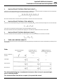
T Machine checked according to delivery note. All attached parts removed. All safety equipment, drive shaft and operating
devices at hand.
T Operation and maintenance of machine and/or implement according to operating instructions explained to the customer.
T Tyres checked re. correct pressure.
T Wheel nuts checked re. tightness.
T Drive shaft cut to correct lenght.
T *VYYLJ[WV^LY[HRLVɈZWLLKPUKPJH[LK
T Fitting to tractor carried out: to three-point linkage
T Trial run carried out and no defects found.
T Functions explained during trial run.
T Pivoting in transporting and operating position explained.
T Information given re. optional extras.
T Absolute need to read the operating manual indicated.
Please check. X
According to the product liability please check the above mentioned items.
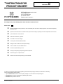
INSTRUCTIONS FOR
PRODUCT DELIVERY
GB
In order to prove that the machine and the operating manual have been properly delivered, a confirmation is necessary.
For this purpose please do the following:
- sign the document A and send it to the company Pöttinger or via the internet to www.poettinger.at
- document B stays with the specialist factory delivering the machine.
- document C stays with the customer.

- 4 -
GB TABLE OF CONTENTS
0400_GB-Inhalt_217
Recommendations
for work safety
All points refer-
ing to safety in
this manual are
indicated by this
sign.
Table of contents
Recommendations for work safety ..........................5
Meaning of warning signs ........................................5
Hitching EUROHIT 91 AZ .........................................6
First connection to tractor ........................................6
Length of the drive shaft ...........................................6
EUROHIT 91 NZ .......................................................7
Hitching EUROHIT 91 NZ .........................................8
Locking the headstock during use on roads and
when lowering .........................................................8
Release rope .............................................................8
Upper link .................................................................8
Hydraulic connection ................................................9
Hydraulic connection EUROHIT 91 AZ .....................9
Hydraulic connection EUROHIT 91 NZ ....................9
Parking the implement ..............................................6
Danger of tipping with the
EUROHIT 91 AZ ..................6
Parking in the open ...................................................7
”SELECT CONTROL” Operating unit ......................7
Tine inclination ........................................................12
Adjustment of rotor inclination ...............................12
General guidelines for working with the machine ...13
Beware! Implements with three-point-linkage ........13
Operating on slopes ...............................................13
Adjustment to implements with three-point-linkage .13
Adjustment to implements with chassis .................13
P.t.o. speed .............................................................13
Clearing field edges (border tedding) to the left or to
the right ..................................................................14
EUROHIT 91 AZ ......................................................14
EUROHIT 91 NZ .....................................................14
Anti-vibration braces ..............................................15
Tine adjustment ......................................................15
Driving on public roads ...........................................16
Locking the headstock during use on roads
EUROHIT 91 NZ
.... 16
Telescopic upper link (optional extra for
EUROHIT 91 NZ)
........16
Changing for EUROHIT 91 NZ
....................................17
Changing for EUROHIT 91 AZ without „Select Control“ ...18
Changing for EUROHIT 91 AZ with „Select Control“ ........19
”SELECT CONTROL” Operating unit .....................20
Carry out required hydraulic function .....................20
Sensor diagnostic function .....................................20
Function check for ”Select Control” operating unit
and job calculator ...................................................20
Disruptions and remedies to power failure ............21
Safeguarding the electrical unit ..............................21
Job calculator layout plan (from 2004 model) .......22
Job calculator plan (up to 2003 model) ..................23
Hydraulics plan .......................................................23
MAINTENANCE
Safety points ...........................................................24
General maintenance hints .....................................24
Cleaning of machine parts ......................................24
Parking in the open .................................................24
Winter storage ........................................................24
Drive shafts .............................................................24
Hydraulic unit ..........................................................24
After the first hours of operation .............................25
Changing tines ........................................................25
Drive shafts .............................................................25
Gas container .........................................................25
Intake transmission ................................................26
Adjustment of sensors ............................................26
Claw coupling .........................................................26
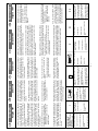
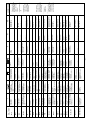
Tecnical Data ..........................................................28
Optional equipment ................................................28
The defined use of the rotary tedder ......................28
SUPPLEMENT
Recommendations for work safety ........................31
DRIVESHAFT ..........................................................32
Lubrication chart .....................................................33
Lubricants ...............................................................35
Fitting windrowing gear ..........................................37
Important! Additional information ...........................38
Combination of tractor and mounted implement ..............38

GB
7!2.).' 3)'.3
- 5 -
?'"7!2."),$%2?
495.173
CTC
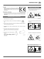
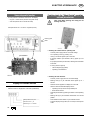
CE sign
The CE sign, which is affixed by the manufacturer,
indicates outwardly that this machine conforms to the
engineering guideline regulations and the other relevant
EU guidelines.
EU Declaration of Conformity
By signing the EU Declaration of Conformity, the manufacturer declares that the
machine being brought into service complies with all relevant safety and health
requirements.
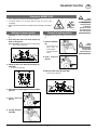
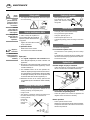
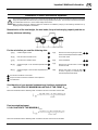
Meaning of warning signs
Never reach into the crushing danger area
as long as parts may move.
Do not enter rotor area while driving motor
is running.
Stay clear of swinging area of implements
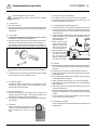
Recommendations for work safety
1. Observe safety hints in supplement
2. All points referring to satety in this manual are indicated by this
sign.
3. Beware! Danger of tipping! Only convert from operating to transport position on
even, firm ground, never on a slope.
4. Only allow rotors to rotate in operating position, never in raised or transport
positions.
5. Always fasten upper steering mechanism lock bolt and
lower steering mechanism link bolt securely with positive
fit.
6. Always take note of warning signs on
machine.
Always replace missing or damaged
warning signs immediately (see list of
spare parts).
Danger - flying objects; keep safe distance from the
machine as long as the engine is running.

GB
()4#().'
- 6 -
'" !."!5?
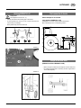
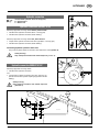
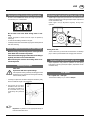
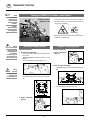
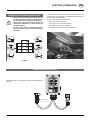
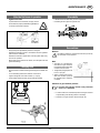
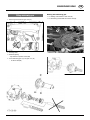
Hitching EUROHIT 91 AZ
Safety hints:
see Supplement-A1 Pkt. 8a. - h.)
- Hitching the machine to the lifting gear of the tractor.
- Fix the hydraulic lower link (U) in such a way that the machine
cannot swing out sideways.
- Raise jackstand (5) and secure with bolt.
Variation 1
Variation 2
First connection to tractor
Check interspaces ”A1 and A2”
(only applies to EUROHIT 91 AZ)
Interspaces ”A1 and A2” should measure about equal.
Mount bracket (B) in the corresponding position.
Length of the drive shaft
(EUROHIT 91 AZ und EUROHIT 91 NZ)
- Before using for the first time, the length of the drive shaft must
be checked and adjusted if necessary (see also supplement B
"Drive shaft adaption").
" "
,

GB
()4#().'
- 7 -
'" !."!5?
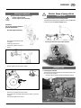
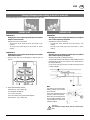
Attention fall-danger, while the machine
is coupled at the tractor.
Before lift the implement:
• The two lower link right arrests (1).
• The upper-link installs (2)!
(only EUROHIT 91 NZ)
Attention fall-danger (G), while the two
rotor-units are waved (B2).
• The implement must be coupled at the tractor!
EUROHIT 91 NZ
#
(

GB
()4#().'
- 8 -
'" !."!5?
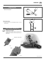
Hitching EUROHIT 91 NZ
Safet hints:
see Supplement-A1 Pkt. 7.), 8a. - 8h.)
1. Pinning the machine to the three point linkage.
2. Fix the hydraulic lower link (4) in such a way that the machine cannot
swing out sideways.
3. Push in the support foot (5) and secure.
Locking the headstock during use on roads and
when lowering
For transport the headstock (SB) must be locked using a lock nut.
A = working position
B = transport position
Important!
Only reposition the lock pin when the machine is in the raised position.
Release rope
- Run rope (S) into tractor cabin.
Upper link
Important!
When using a telescopic upper link, observe the
notes in the chapter "TRANSPORT POSITION".
4$
%
*
&
(#
'
/-
$;
1-
)

GB
()4#().'
- 9 -
'" !."!5?
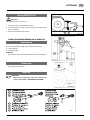
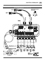
Hydraulic connection EUROHIT 91 NZ
Necessary equipment for towing vehicle:
• a double-action hydraulic connection
and
• a single-action hydraulic connection with return pipe (only ap-
plies to machines with hydraulic adjusting equipment for border
tedding)
Safety warning
Only transport machine with closed stopcock
(position A)
Hydraulic connection
connect both hydraulic lines correctly (P/T)
P = Pressure line
T = Return line
Hydraulic connection EUROHIT 91 AZ
Necessary equipment for towing vehicle without „Select Control“:
• a double-action hydraulic connection (Rotor + Running gear)
• a double-action hydraulic connection (border tedding)
Necessary equipment for towing vehicle with „Select Control“:
• a single-action hydraulic connection with return pipe (Rotor + Running gear)
• a double-action hydraulic connection (border tedding)
Connecting hydraulic systems to the tractor
- Only connect hydraulic system to the tractor when stopcock is closed (position A).
Safety warning
Only transport machine with closed stopcock (position A).
&8
%8
%8
1
5
1
5

GB
0!2+).'
- 10 -
'"!"34%,,%.?
Attention! Danger of tipping with the
EUROHIT 91 AZ
• Lowering the machine frome working position.
The implement can be parked only when the running gear (Pos. A)
is lowered, otherwise danger of tipping exists!
Parking the implement
Always park the implement securely!
- use the support stand.
- Secure support stand properly.
Attention!
Do not use the feeler wheel to
park the implement!
- Use the support stand (5).
- Pull off drive shaft (GW) and rest
on support.
- Close stop cock (Pos. A)
- Disconnect hydraulic lines from
tractor.
- Remove release rope from tractor cabine.
- Remove pull rope (EL) from tractor cabin.
This prevents the unwanted discharge of the battery, e.g. during
the night.
- Disconnect appliance from tractor.
EUROHIT 91 NZ
• Lowering the machine
The machine can be lowered both from the working position and
from the transport position.
- Use both support stands (5) (otherwise danger of tipping).
• Lowering the machine from transport position.
&-

GB
0!2+).'
- 11 -
'"!"34%,,%.?
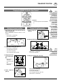
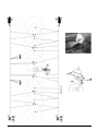
Parking in the open
• When parking for longer periods in the open, clean plunger rods
and then coat with grease.
Check when parking
• So that rain water can run off unhindered, the holes " W" must
not be blocked.
”SELECT CONTROL” Operating unit (W
Always place the operating unit where it is pro-
tected from the weather.
A holding clamp, in which to place the operating unit, is
located on the underside of the mounting frame (up to
2003 model).
Magnet (from 2004 model)
8
4$
'&55
W) W) Optional equipment

- 12 -
GB
'" 6/2%).34%,,5.'%.?
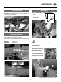
!$*534-%.43 "%&/2% /0%2!4)/.
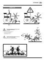
Adjustment of rotor inclination
• Running axles can be adjusted to 5 different settings at the gearing
(A) (1 setting = 1° alteration to rotor inclination).
Important!
Check that nut fits tight, to prevent
gearing (A) getting worn
Starting torque
Screw thread M20: 410 Nm (41 kpm)
Screw thread M16: 215 Nm (21 kpm)
A lot of fodder = greater angle.
Not much fodder = smaller angle.
Safety hints:
All work in the immediate area of the rotors may only
be carried out when the p.t.o. is switched off.
Caution!
Do not enter rotor area while driving motor is running.
Note: Some of the diagrams in this operating manual are only symbolic
representations. They are useful for better explanations,
but they can differ slightly from the real situation.
Tine inclination
• It is also important that tine inclination is correct (see chapter
"USE").
495.173
4
4
4$
3

GB
USE
- 13 -
'"%).3!4:?
General guidelines for working with the machine
- All work in the immediate area of the rotors may only be carried
out when the p.t.o. is switched off.
Do not enter rotor area while driving motor is run-
ning.
- Choose the speed of travel so that all crops are picked up
thoroughly.
- In cases of overloading, shift down one gear.
- Lift three point follower machine before going around sharp bends
and when reversing.
Beware! Implements with three-point-linkage
Machine swings automatically back to central position
when lifted and is locked into position.
Take care that the swinging machine does not endanger
anybody and does not hit solid obstacles.
When lowering the machine the locking devise is au-
tomatically lifted.
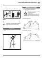
Operating on slopes
Take note!
implements with three-point-linkage
If the implement is being raised by the lifting gear whilst
travelling in a curve, the implement swings automatically
into the central position.
- If working on slopes this can lead to dangerous situations, partly
due to the balance weight of the implement.
• The function of the shock
absorbtion struts is to allow
the swinging procedure to
be executed slowly and
continuously, not in jerks and
jolts.
Important! Pay attention to the appropriate setting of
both shock absorber struts.
Adjustment to implements with three-point-linkage
- Adjust length of upper link (9) so that rotors are inclined forward
and spring tines lightly touch the ground (see chapter „Adjustment
of rotor inclination“ also).
Check upper link (9) adjustment regularly during work
operation.
Setting lower link
- Tractor‘s lower link (4) must be set so that there is no sideways
play in order to prevent tedder from swinging back and forth.
Adjustment to implements with chassis
- Adjust implement using tractor‘s hydraulics so that spring
tines lightly touch the ground (see chapter „Adjustment of rotor
inclination“ also).
P.t.o. speed
- P.t.o. speed max. = 540 rpm
The most favourable p.t.o. rpm is about 450 rpm.
4$
495.173

GB
USE
- 14 -
'"%).3!4:?
Note
The slanting axles make border
tedding possible with the three
point machines.
In this working position the swivel
area (9) is used to its full extent.
When driving around bends away
from the edge of the field or at the
end of the field, the machine must
therefore be lifted.
Attention!
The machine swings back into the central posi-
tion.
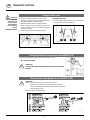
Clearing field edges (border tedding) to the left or to the right
Clearing field edges can be carried out by swinging the runner wheel.
EUROHIT 91 AZ
VARIATION 1
Swinging the runner wheels hydraulically on machines
without “Select Control”
- Operate servo-valve on the tractor.
- To swing the runner wheel left move servo-valve to „lift“
position.
- To swing runner wheel right move servo-valve to „lower“
position.
VARIATION 2
Swinging the runner wheels hydraulically on machines
with “Select Control”
1. Lifting up the rotor units hydrauliqually a little bit from the
ground
2. Select desired tedding direction
Press button (4 or 5) (= select ON)
The integrated LED lights up
- Turn on servo-valve (ST)
The runner wheels swing in the desired direction
Press button (4 or 5) (= select OFF)
EUROHIT 91 NZ
VARIATION 1
Swinging the runner wheel hydraulically on machines
with central adjusting equipment
- Operate servo-valve on the tractor.
- To swing the runner wheel left move servo-valve to „lift“
position.
- To swing runner wheel right move servo-valve to „lower“
position.
VARIATION 2
Swinging the runner wheel mechanically on machines
with central adjusting equipment
- Release locking bolts by pulling the rope (S).
- Turn the tractor wheels in the direction of the field edge and drive
forward at the same time. The machine‘s runner wheels swing in
the opposite direction.
- Let go of the rope (S) and make sure that the locking bolt are
correctly engaged.
45

GB
USE
- 15 -
'"%).3!4:?
Anti-vibration braces
EUROHIT 91 NZ
Anti-vibration braces bring about quiet machine running during
operation.
Remedy for noisy machine running:
Spring washer tension and friction element (R) pressure on the
pressure can be altered by turning hexagonal nut (SK).
4$
44
4$
3
4$
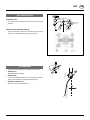
Tine adjustment
Tine position can be altered by turning the tine carrier (80).
• Position „S1“
Standard position (ex factory)
• Position „S2“
For use under difficult conditions, e. g. with very dense, awkward
forage. This tine position increases the strewing action.
• Direction of rotation „R“
Be aware of this when installing tines.

- 16 - 0500_GB-Transport_217
GB TRANSPORT POSITION
Hydraulic lower link
• Fix the hydraulic lower link (U) in such a way that the
machine cannot swing out sideways.
Locking the headstock during use on roads EUROHIT 91 NZ
For transport the headstock (SB) must be locked using a lock nut.
B = transport position
Important!
Only reposition the lock pin when the machine is in the raised
position.
• Observe the official regulations of your country.
• Travelling on open roads may only be carried out as
described in chapter „Transport position“.
• Protection devices must be in proper condition.
• Before travelling bring all swivelling parts into their
correct positions and secure against dangerous
changes to position.
• Check that lighting functions before travelling.
%
*
&
(#
'
/-
$;
1-
)
Telescopic upper link (optional extra for EUROHIT 91 NZ)
Important!
Always lock the telescopic upper link (transport position)
- when the rotor units are swung up in the transport position
- when the implement has been lifted with the tractor‘s lifting gear
- when travelling on roads
Otherwise danger of tipping exists!
Driving on public roads
IImportant!
mportant
information can
also be found in
the supplement
of this operating
manual.

- 17 -
0500_GB-Transport_217
GB
TRANSPORT POSITION
Changing for EUROHIT 91 NZ
• Only transport the machine in the transport position!
• For safety reasons, turn off drive shaft and wait for rotor to stop
completely.
• Make sure that swivel area is free and that nobody is standing in the danger
area.
Safety
Precaution!
Changing from
working position
to transport
position is only to
be carried out on
even, firm ground.
Working to transport position
Important! The order of operation must be adhered
to.
1. First swing the outer rotor units all the way
down to the ground
This is important, otherwise collision in final position!
- Turn on servo-valve (ST)
2. Swing up outer rotor units into transport po-
sition (B1)
- Turn on servo-valve (ST)
3. Lift machine using lifting gear on towing vehicle
(pos. A1)
4. Close stopcock
(pos. A)
5. Locking the head-
stock (B)
Transport to working position
Important! The order of operation must be adhered
to.
1. Unlock headstock
(A)
- Lift machine using
lifting gear on
towing vehicle
- Put bolt into bore-
hole A
2. Open stopcock
(pos. E)
3. Swing up outer rotor units (pos. B2)
- Turn on servo-valve (ST)
#
#
#
"
Safety
warning
Only transport
machine with
closed stopcock.

- 18 - 0500_GB-Transport_217
GB TRANSPORT POSITION
• Only transport the machine in the transport position!
• For safety reasons, turn off drive shaft and wait for
rotor to stop completely.
• Make sure that swivel area is free and that nobody is
standing in the danger area.
Changing for EUROHIT 91 AZ without „Select Control“
Safety
Precaution!
Changing from
working position
to transport
position is only to
be carried out on
even, firm ground.
Working to transport position
Function sequence:
1. Turn on servo-valve (ST)
- Firstly, the outside rotary units are swung down to
the ground
This is important, otherwise collision in final
position!
- The running gear swings upwards (pos. A1)
- The outside rotary units are swung upwards (pos.
B1)
2. Close stopcock
(pos. A)
Transport to working position
Function sequence:
1. Open stopcock
(pos. E)
2. Turn on servo-valve (ST)
- The outside rotary units are swung downwards (pos.
B2)
- The running gear swings up (pos. A2)
Safety
warning
Only transport
machine with
closed stopcock.
Transport position
EUROHIT 91 AZ
#
"
#
Note!
Necessary
equipment for
towing vehicle
without „Select
Control“:
• a double-
action hydraulic
connection (Rotor
+ Running gear)

- 19 -
0500_GB-Transport_217
GB
TRANSPORT POSITION
Changing for EUROHIT 91 AZ with „Select Control“
Safety
Precaution!
Changing from
working posi-
tion to transport
position is only to
be carried out on
even, firm ground.
• Only
transport the
machine in the
transport posi-
tion!
• For safety
reasons, turn off
drive shaft and
wait for rotor to
stop completely.
• Make sure that
swivel area is free
and that nobody
is standing in the
danger area.
Working to transport position
1. First swing the outer rotor units all the way
down to the ground
This is important, otherwise collision in final
position!
- Press button 1 (= select ON)
- Turn on servo-valve (ST)
2. Swing down running gear (Pos. A1)
- Press button 6 (= select ON)
The integrated LED lights up
- Turn on servo-valve (ST)
The running gear swings upwards
3. Swing up the outer
rotor units (pos.
B1)
- Press button 4 (=
select ON)
- Turn on servo-valve
(ST)
- Press button 4 (=
select OFF)
4. Close stopcock
(pos. A)
Transport to working position
1. Open stopcock
(pos. E)
2. Swing up outer rotor units (pos. B2)
- Press button 1 (= select ON)
- Turn on servo-valve (ST)
3. Swing up running gear (Pos. A2)
- Press button 3 (= select ON)
The integrated LED lights up
- Turn on servo-valve (ST)
The running gear swings up (pos. A2)
- Press button 3 (= select OFF)
1
3
4
6
#
"
Safety
warning
Only transport
machine with
closed stopcock.
Important!
The order of operation must be adhered
to.
#

- 20 - 0500-GB-SELECT-CONTROL_217
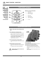
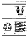
GB SELECT CONTROL - SELECTION
1
2
3
4
5
6
7
Note:
Operation is carried
out as selection
To activate a func-
tion it must be
selected through
the button on the
control panel
The function is car-
ried out through a
single or double-
action hydraulic
control valve on
the tractor
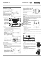
Meaning of control panel buttons
1 Lower rotors
2 Tedding limit right
3 Raise running gear
4 Raise rotors
5 Tedding limit left
6 Lower running gear
7 On- / Off
”SELECT CONTROL” Operating unit
1. Switch control panel on by pressing button
“I/O”
2. Press the button for desired function
- The control light (LED) integrated in the button lights
up.
- Through pressing any other button, the hydraulic
function already selected will be deactivated, and
the new hydraulic function activated.
- Pressing button a second time deactivates the
hydraulic function once more.
3. Turn on servo-valve on towing vehicle
- and the desired hydraulic function will be carried
out.
4. Deactivating the hydraulic function
- Press button, the integrated control light (LED) goes
off.
- The hydraulic function has been deactivated.
Safety warning: always deactivate the
selected function.
Control light (LED)
If one of the control lights (LEDs) lights up, it means that
that particular function has been activated.
The example on the illustration above shows
- The top left integrated control light (LED) is on
- Lowering of the outer rotor units has been
activated
- Function is carried out through hydraulic control
valve on tractor.
Carry out required hydraulic function
La pagina si sta caricando...
La pagina si sta caricando...
La pagina si sta caricando...
La pagina si sta caricando...
La pagina si sta caricando...
La pagina si sta caricando...
La pagina si sta caricando...
La pagina si sta caricando...
La pagina si sta caricando...
La pagina si sta caricando...
La pagina si sta caricando...
La pagina si sta caricando...
La pagina si sta caricando...
La pagina si sta caricando...
La pagina si sta caricando...
La pagina si sta caricando...
La pagina si sta caricando...
La pagina si sta caricando...
La pagina si sta caricando...
La pagina si sta caricando...
La pagina si sta caricando...
La pagina si sta caricando...
-
 1
1
-
 2
2
-
 3
3
-
 4
4
-
 5
5
-
 6
6
-
 7
7
-
 8
8
-
 9
9
-
 10
10
-
 11
11
-
 12
12
-
 13
13
-
 14
14
-
 15
15
-
 16
16
-
 17
17
-
 18
18
-
 19
19
-
 20
20
-
 21
21
-
 22
22
-
 23
23
-
 24
24
-
 25
25
-
 26
26
-
 27
27
-
 28
28
-
 29
29
-
 30
30
-
 31
31
-
 32
32
-
 33
33
-
 34
34
-
 35
35
-
 36
36
-
 37
37
-
 38
38
-
 39
39
-
 40
40
-
 41
41
-
 42
42


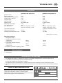
Pottinger EUROHIT 91 A Istruzioni per l'uso
- Tipo
- Istruzioni per l'uso
- Questo manuale è adatto anche per
in altre lingue
Documenti correlati
-
Pottinger HIT 610 NZ Istruzioni per l'uso
-
-
-
-
-
-
-
-
-