Falmec FDPST26W5SG Manuale del proprietario
- Categoria
- Cappe da cucina
- Tipo
- Manuale del proprietario
Questo manuale è adatto anche per

IT LIBRETTO ISTRUZIONI
UK INSTRUCTIONS BOOKLET
DE GEBRAUCHSANWEISUNG
FR MODE D'EMPLOI
ES MANUAL DE INSTRUCCIONES
RU ИНСТРУКЦИИ
PL INSTRUKCJA OBSŁUGI
NL HANDLEIDING
PT MANUAL DE INSTRUÇÕES
DK BRUGSANIVSNINGER
SE INSTRUKTIONSBOK
FI OHJEKIRJA
NO BRUKSANVISNING
Prestige
parete / wall

2
ø8 mm
ø6 mm
200
654
520
86
409
49
Ø150
215
1086
621
402
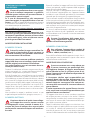
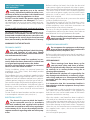
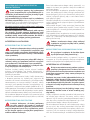
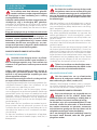
PRESTIGE 65: 22 kg

3
260 mm
356 mm
10 mm
116 mm
150 mm
ø150 mm
ø150
mm
min. 300 mm
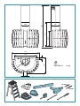
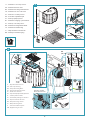
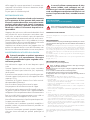
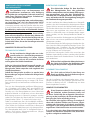
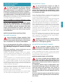
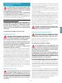
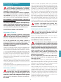
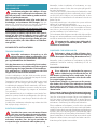
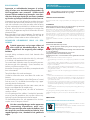
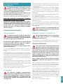
IT - Misure per l’installazione.
UK - Measurements for installation.
DE - Maßangaben für die Installation.
FR - Mesures pour l'installation.
ES - Medidas para la instalación.
RU - Размеры для установки.
PL - Środki montażowe.
NL - Maten voor de installatie.
PT - Medidas para a instalação.
DK - Mål for installation.
SE - Installationsåtgärder.
FI - Mitat asennusta varten.
NO - Installasjonsmål.
1
H
356 mm
600 mm
4
Ø8 mm
V1 (x2)
S
356 mm
2
3
x2
1

4
4
2
3
1
C
B
5
V3 (x2)
6
2
M
1
3
4
Ø15
150mm
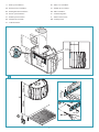
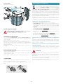
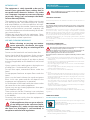
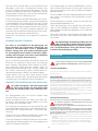
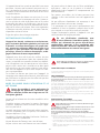
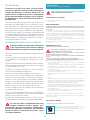
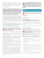
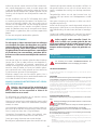
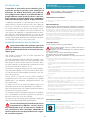
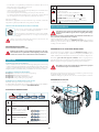
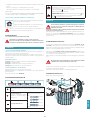
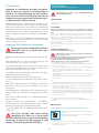
IT - Fissaggio cappa (2), installazione valvola di non ritor-
no (3) e montaggio tubo d’aspirazione (4).
UK - Hood fastening (2), check valve installation (3) and
suction pipe assembly (4).
DE - Befestigung der Abzugshaube (2), Installation des
Rückschlagventils (3) und Montage der Ansauglei-
tung (4).
FR - Fixation de la hotte (2), installation du clapet anti-re-
tour (3) et montage du tuyau d'aspiration (4).
ES - Fijación de la campana (2), instalación de la válvula
antirretorno (3) y montaje del tubo de aspiración (4).
RU - Крепление вытяжки (2), установка обратного кла-
пана (3) и монтаж всасывающей трубы (4).
PL - Mocowanie okapu (2), montaż zaworu zwrotnego (3) i
montaż rury ssącej (4).
NL - Kapbevestiging (2), montage terugslagklep (3) en
zuigleiding. (4)
PT - Fixação do exaustor (2), instalação da válvula de não
retorno (3) e montagem do tubo de aspiração (4).
DK - Fastgørelse af emhætten (2), montage af kontraventil
(3) og rør til udsuget (4).
SE - Fästning av kåpan (2), installation av backventilen (3)
samt montering av utsugningsröret (4).
FI - Liesituulettimen kiinnitys (2), vastaventtiilin asennus
(3) ja imuputken liitäntä (4).
NO - Feste av ventilatorhette (2), installasjon av tilbake-
slagsventil (3) og montasje av innsugingsrør (4).
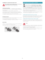
IT - Viti di sicurezza obbligatorie.
UK -
Mandatory safety screws.
DE - Sicherheitsschrauben obligatorisch.
FR - Vis de sécurité obligatoires.
ES - Tornillos de seguridad obligatorios.
RU - Обязательные предохранительные
винты.
PL - Obowiązujące śruby zabezpieczające.
3
4
2
NL - Verplichte veiligiheidsschroeven.
PT - Parafusos de segurança obriga-
tórios.
DK -
Obligatoriske sikkerhedsskruer.
SE -
Obligatoriska säkerhetsskruvar
.
FI -
Pakolliset varmistusruuvit
.
NO -
Påkrevde sikkerhetsskruer
.

55
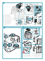
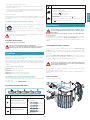
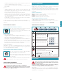
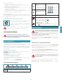
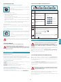
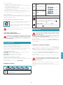
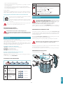
IT - Installazione con uscita posteriore
UK - Installation with rear outlet
DE - Installation mit abzug auf der Rückseite
FR - Installation avec une sortie arrière
ES - Instalación con salida posterior
RU - Установки с задним выводом
PL - Instalacji z tylnym wylotem
NL - Installatie met uitgang op de achterkant
PT - Instalação com saída posterior
DK - Installation med bagudvendt aftræk
SE - Installation med bakre uttag
FI - Takapoistumistien asentamiseksi
NO - Installasjon med bakre utgang.
Connettore comandi
Panel control connector
V7
(x6)
Cavo alimentazione
Power cable
4
5
7
8
6
3
1
2
5
6
1
H
356 mm
600 mm
4
Ø8 mm
V1 (x2)
S
356 mm
2
3
x2
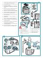
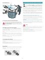
IT - Riposizionamento motore
UK - Motor repositioning
DE - Neupositionierung Motor
FR - Repositionnement du moteur
ES - Reubicación del motor
RU - Перепозиционирование двигателя
PL - Zmiana położenia silnika
NL - Hernieuwde plaatsing van de motor
PT - Reposicionamento do motor
DK - Genpositionering af motor
SE - Ompositionering motor
FI - Moottorin uudelleensijoitus
NO - Gjenplassering av motor

6
4
2
3
1
C
B
5
V3 (x2)
6
M
1
2
3
4
9
7
8
V8
(x2)
4
T
Connettore comandi
Panel control connector
Cavo alimentazione
Power cable
6
7
T
V7
(x4)
1
2
3
5
IT - Viti di sicurezza obbligatorie
UK - Mandatory safety screws
DE - Sicherheitsschrauben, obligatorisch
FR - Vis de sécurité obligatoires
ES - Tornillos de seguridad obligatorios
RU - Обязательные предохранитель-
ные винты
PL -
Obowiązkowe śruby zabezpieczające
NL - Verplichte veiligheidsschroeven
PT -
Parafusos de segurança obrigatórios
DK - Obligatoriske sikkerhedsskruer
SE - Obligatoriska säkerhetsskruvar
FI - Pakolliset varmistusruuvit
NO - Påkrevde sikkerhetsskruer
IT - Riposizionamento motore
UK - Motor repositioning
DE - Neupositionierung Motor
FR - Repositionnement du moteur
ES - Reubicación del motor
RU - Перепозиционирование двигателя
PL - Zmiana położenia silnika
NL -
Hernieuwde plaatsing van de motor
PT - Reposicionamento do motor
DK - Genpositionering af motor
SE - Ompositionering motor
FI - Moottorin uudelleensijoitus
NO - Gjenplassering av motor

7
1
4
Ø6 mm
Ø6
Ø6
V4 (x2)
5
V5
(x2)
L
H
3
L
2
V3 (x4)
G
H
2
1
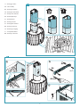
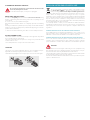
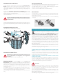
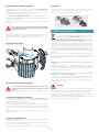
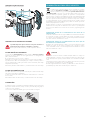
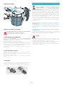
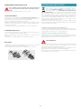
IT - Montaggio camino.
UK - Flue assembly.
DE - Montage des Kamins.
FR - Montage de la cheminée.
ES - Montaje de la chimenea.
RU - Монтаж дымохода.
PL - Montaż komina.
NL - Montage schacht.
PT - Montagem da chaminé.
DK - Montage af skorsten.
SE - Montering av rökgång.
FI - Poistoputken liitäntä.
NO - Montasje av skorstein.
10
11

8
12
13
21
3
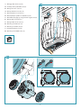
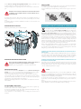
IT - Montaggio ltro di serie (12)+(13).
UK - Assembly of factory-tted lter (12)+(13).
DE - Montage des Serien- (12)+(13).
FR - Montage du ltre de série (12)+(13).
ES - Montaje del ltro de serie (12)+(13).
RU - Монтаж фильтра серийного оснащения (12)+(13).
PL - Montaż ltra występującego w wyposażeniu seryjnym (12)+(13).
NL - Montage lter, serieel (12)+(13).
PT - Montagem ltro de série (12)+(13).
DK - Montering af serielter (12)+(13).
SE - Montering av serielter (12)+(13).
FI - Varusteluun kuuluvan (12)+(13).
NO - Montering av standardlter (12)+(13).

ITALIANO
9
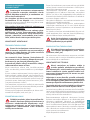
ISTRUZIONI DI SICUREZZA
E AVVERTENZE
Il lavoro d’installazione deve essere esegui-
to da installatori competenti e qualicati,
secondo quanto indicato nel presente libretto e
rispettando le norme in vigore.
Se il cavo di alimentazione o altri componenti
sono danneggiati, la cappa NON deve essere uti-
lizzata: staccare la cappa dall'alimentazione elettrica
e contattare il Rivenditore o un Centro Assistenza Tec-
nica autorizzato per la riparazione.
Non modicare la struttura elettrica, meccanica e
funzionale dell'apparecchiatura.
Non tentare di eettuare da soli riparazioni o so-
stituzioni: gli interventi eettuati da persone non
competenti e qualicate possono provocare dan-
ni, anche molto gravi, a cose e/o persone non co-
perti da garanzia del Costruttore.
AVVERTENZE PER L'INSTALLATORE
SICUREZZA TECNICA
Prima di installare la cappa controllare l'in-
tegrità e funzionalità di ogni sua parte: se
si notano anomalie non procedere nell'installa-
zione e contattare il Rivenditore.
Nel caso sia stato riscontrato un difetto estetico la
cappa NON deve essere installata; riporla nel suo
imballo originale e contattare il Rivenditore.
Una volta installata non sarà accettato alcun re-
clamo per difetti estetici.
Durante l'installazione utilizzare sempre mezzi di pro-
tezione personale (es.: scarpe antiinfortunistiche) ed
adottare comportamenti prudenti e corretti.
Il kit di fissaggio (viti e tasselli) fornito con la cappa è
utilizzabile unicamente su pareti in muratura: in caso
di installazione su pareti di materiale diverso, valutare
altri sistemi di fissaggio tenendo conto della resisten-
za del muro e del peso della cappa (indicato a pag. 2).
Tenere presente che l’installazione con sistemi di fis-
saggio diversi da quelli forniti o non conformi può
comportare rischi di natura elettrica e di tenuta mec-
canica.
Non installare la cappa in ambienti esterni e non
esporla ad agenti atmosferici (pioggia, vento, ecc...).
SICUREZZA ELETTRICA
L’impianto elettrico al quale viene collega-
ta la cappa deve essere a norma e munito
di collegamento a terra secondo le norme di si-
curezza del Paese di utilizzo; deve essere inoltre
conforme alle normative Europee sull’antidistur-
bo radio.
Prima di installare la cappa verificare che la tensione
di rete corrisponda a quella riportata dalla targhetta
posta all’interno della cappa.
La presa usata per il collegamento elettrico deve es-
sere facilmente raggiungibile con l’apparecchiatura
installata: in caso contrario, prevedere un interruttore
generale per disconnettere la cappa al bisogno.
Ogni eventuale modifica all’impianto elettrico dovrà
essere eseguita solo da un elettricista qualificato.
La lunghezza massima della vite di fissaggio del cami-
no (fornita dal fabbricante) è di 13 mm. L'utilizzo di viti
non conformi con le presenti istruzioni può compor-
tare rischi di natura elettrica.
In caso di malfunzionamenti dell’apparecchio, non
tentare di risolvere da soli il problema, ma contatta-
re il Rivenditore o un Centro di Assistenza autorizzato
per la riparazione.
Durante l'installazione della cappa, disin-
serire l’apparecchio togliendo la spina o
agendo sull’interruttore generale.
SICUREZZA SCARICO FUMI
Non collegare l’apparecchio a condotti di
scarico dei fumi prodotti dalla combustio-
ne (ad es. caldaie, caminetti, ecc...)
Prima dell'installazione della cappa assicurarsi che si-
ano rispettate tutte le normative vigenti sullo scarico
dell’aria all’esterno del locale.
AVVERTENZE PER L'UTILIZZATORE
Queste avvertenze sono state redatte per
la vostra sicurezza e per quella degli altri,
Vi preghiamo, dunque, di leggere attentamente
questo libretto in tutte le sue parti prima di uti-
lizzare l’apparecchio o di eettuare operazioni di
pulizia sullo stesso.
Il Costruttore declina ogni responsabilità per
eventuali danni che possano, direttamente o in-
direttamente, essere causati a persone, cose ed
animali domestici conseguenti alla mancata os-
servanza delle avvertenze di sicurezza indicate in
questo libretto.
È molto importante che questo libretto istruzio-
ni sia conservato insieme all’apparecchiatura per
qualsiasi futura consultazione.
Se l’apparecchio dovesse essere venduto o trasferito
ad un’altra persona, assicurarsi che anche il libretto
venga fornito, in modo che il nuovo utente possa es-
sere messo al corrente del funzionamento della cap-
pa e delle avvertenze relative.
Dopo l’installazione delle cappe in acciaio inox è ne-
cessario eseguire la pulizia della stessa per rimuove-
re i residui di collante del protettivo e le eventuali
macchie di grasso e oli, che, se non rimosse, possono
causare il deterioramento irreversibile della superficie

10
della cappa. Per questa operazione il costruttore rac-
comanda l’utilizzo delle salviette in dotazione, dispo-
nibili anche in acquisto
Esigere parti di ricambio originali.
DESTINAZIONE D'USO
L’apparecchio è destinato solo ed esclusivamente
per l'aspirazione di fumi generati dalla cottura di
alimenti in ambito domestico, non professionale:
qualsiasi utilizzo diverso da questo è improprio,
può provocare danni a persone, cose ed animali
domestici e solleva il Costruttore da qualsiasi re-
sponsabilità.
L’apparecchio può essere utilizzato da bambini di età
non inferiore a 8 anni e da persone con ridotte capa-
cità fisiche, sensoriali o mentali, o prive di esperienza
o della necessaria conoscenza, purché sotto sorve-
glianza oppure dopo che le stesse abbiano ricevuto
istruzioni relative all’uso sicuro dell’apparecchio e alla
comprensione dei pericoli ad esso inerenti.
I bambini non devono giocare con l’apparecchio. La
pulizia e la manutenzione a cura dell’utilizzatore non
deve essere effettuata da bambini senza sorveglianza.
AVVERTENZE PER L'UTILIZZO E LA PULIZIA
Prima di procedere a qualsiasi operazione
di pulizia o di manutenzione, disinserire
l’apparecchio togliendo la spina o agendo sull’in-
terruttore generale.
Non utilizzare la cappa con le mani bagnate o piedi
scalzi.
Quando l’apparecchio non viene usato, controllare
sempre che tutte le parti elettriche, (luci, aspiratore),
siano spente.
Il peso massimo complessivo di eventuali oggetti po-
sizionati o appesi (ove previsto) sulla cappa non deve
superare 1,5 Kg.
Controllare le friggitrici durante l’uso: I’olio surriscal-
dato potrebbe infiammarsi.
Non accendere fiamme libere sotto la cappa.
Non preparare cibi alla fiamma sotto la cappa.
Non utilizzare mai la cappa senza i filtri metallici antigras-
so; grasso e sporco in questo caso si depositerebbero
nell'apparecchio compromettendone il funzionamento.
Parti accessibili della cappa possono essere calde se
utilizzate insieme con apparecchi di cottura.
Non effettuare operazioni di pulizia quando parti del-
la cappa sono ancora calde.
Se la pulizia non è condotta secondo le modalità e i
prodotti indicati nel presente libretto è possibile un
rischio di incendio.
Disinserire l’interruttore generale quando l’apparec-
chio non viene utilizzato per periodi prolungati di
tempo.
In caso di utilizzo contemporaneo di altre
utenze (caldaie, stufe, caminetti, ecc.) ali-
mentate a gas o con altri combustibili, provvede-
re ad una adeguata ventilazione del locale in cui
avviene l’aspirazione dei fumi, secondo le norme
vigenti.
INSTALLAZIONE
parte riservata solo a personale qualicato
Prima di eettuare l'installazione della cappa, leggere attenta-
mente il cap. "ISTRUZIONI DI SICUREZZA E AVVERTENZE".
CARATTERISTICHE TECNICHE
I dati tecnici dell'apparecchio sono riportati su etichette posizionate all’interno
della cappa.
POSIZIONAMENTO
La distanza minima fra la parte più alta dell'apparecchiatura per la cottura
e la parte più bassa della cappa da cucina viene indicata nelle istruzioni di
montaggio.
In generale, quando la cappa da cucina è posta su un piano cottura a gas, questa
distanza deve essere almeno 65 cm (25,6"). Tuttavia sulla base di un’interpreta-
zione della norma EN60335-2-31 del 11-07-2002 da parte del TC61 (subclause
7.12.1 meeting 15 agenda item 10.11), la distanza minima tra piano cottura e
parte inferiore della cappa può essere ridotta alla quota riportata nelle istruzioni
di montaggio.
Se le istruzioni del piano di cottura a gas specificano una distanza maggiore,
bisogna tenerne conto.
Non installare la cappa in ambienti esterni e non esporla ad agenti atmosferici
(pioggia, vento, ecc...).
COLLEGAMENTO ELETTRICO
(parte riservata solo a personale qualicato)
Prima di eettuare qualsiasi operazione sulla cappa scollegare
l’apparecchio dalla rete elettrica.
Assicurarsi che non vengano scollegati o tagliati li elettrici all’in-
terno della cappa:
in caso contrario contattare il Centro Assistenza più vicino.
Per l’allacciamento elettrico rivolgersi a personale qualicato.
Il collegamento deve essere eseguito in conformità con le disposizioni di
legge in vigore.
Prima di collegare la cappa alla rete elettrica, controllare che:
• la tensione di rete corrisponda a quella riportata sui dati di targa posti all’in-
terno della cappa;
• l’impianto elettrico sia a norma e possa sopportare il carico (vedi caratteristi-
che tecniche posizionate all’interno della cappa);
• la spina e il cavo, di alimentazione, non devono entrare in contatto con tem-
perature superiori a 70 °C;
• l’impianto di alimentazione sia munito di efficace e corretto collegamento di
terra secondo le norme vigenti;
• la presa usata per il collegamento sia facilmente raggiungibile una volta in-
stallata la cappa.
In caso di :
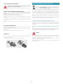
• apparecchi dotati di cavo senza spina: la spina da utilizzare deve essere di tipo
“normalizzato”. Il fili devono essere collegati come segue: giallo-verde per
la messa a terra, blu per il neutro e il filo marrone per la fase. La spina deve
essere collegata ad un'adeguata presa di sicurezza.
• apparecchio fisso non provvisto di cavo di alimentazione e di spina, o di altro
dispositivo che assicuri la disconnessione dalla rete, con una distanza di aper-
tura dei contatti che consenta la disconnessione completa nelle condizioni
della categoria di sovratensione III.
Tali dispositivi di disconnessione devono essere previsti nella rete di alimen-
tazione conformemente alle regole di installazione.
Il cavo di terra giallo/verde non deve essere interrotto dall’interruttore.
Il Costruttore declina ogni responsabilità nel caso le norme di sicurezza non ven-
gano rispettate.

ITALIANO
11
SCARICO FUMI
CAPPA AD EVACUAZIONE ESTERNA ASPIRANTE
In questa versione, fumi e vapori vengono convogliati verso
l'esterno attraverso il tubo di scarico.
A tal fine, il raccordo d'uscita della cappa, deve essere collega-
to tramite un tubo, ad un'uscita esterna.
Il tubo d'uscita deve avere:
• un diametro non inferiore a quello di raccordo della cappa.
• una leggera inclinazione verso il basso (caduta) nei tratti orizzontali per evitare
che la condensa refluisca nel motore.
• il numero minimo indispensabile di curve.
• la lunghezza minima indispensabile per evitare vibrazioni e di ridurre la capa-
cità aspirante della cappa.
E' necessario isolare la tubazione se passa attraverso ambienti freddi.
Per impedire ritorni d'aria dall'esterno, una valvola di non ritorno è presente in
presenza di motori con 800m3/h o superiori.
Deviazione per la Germania:
quando la cappa da cucina e apparecchi alimentati con energia diversa da quel-
la elettrica sono in funzione simultaneamente, la pressione negativa nel locale non
deve superare i 4 Pa (4 x 10⁻⁵ bar).
CAPPA A RICICLO INTERNO FILTRANTE
In questa versione l’aria passa attraverso i filtri al carbone attivo
per essere purificata e riciclata nell’ambiente.
Controllare che i filtri al carbone attivo siano montati sulla cap-
pa, in caso negativo applicarli come indicato nelle istruzioni
di montaggio.
In questa versione valvola di non ritorno non deve essere montata: ri-
muoverla se presente sul raccordo di uscita aria del motore.
ISTRUZIONI DI MONTAGGIO
parte riservata solo a personale qualicato
La cappa ha la possibilità di essere installata in varie congurazio-
ni. Le fasi di montaggio generiche valgono per tutte le installazio-
ni; seguire invece dove specicato le fasi corrispondenti all’instal-
lazione desiderata.
FUNZIONAMENTO
QUANDO ACCENDERE LA CAPPA?
Accendere la cappa almeno un minuto prima di iniziare a cucinare per convo-
gliare fumi e vapori verso la superficie di aspirazione.
Al termine della cottura lasciare in funzione la cappa fino a completa aspirazione
di tutti i vapori e odori: con la funzione Timer, è possibile impostare l'autospegni-
mento della cappa dopo 15 minuti di funzionamento.
QUALE VELOCITÀ SCEGLIERE?
I velocità: mantiene l’aria pulita con bassi consumi di energia elettrica.
II velocità: condizioni normali di utilizzo.
III velocità: presenza di forti odori e vapori.
IV velocità: rapidi smaltimenti di odori e vapori.
QUANDO LAVARE O CAMBIARE I FILTRI?
I filtri metallici devono essere lavati ogni 30 ore di utilizzo.
I filtri carbone attivo, vanno sostituiti ogni 3-4 mesi a seconda dell’utilizzo della
cappa.
Per ulteriori dettagli vedere cap “MANUTENZIONE”.
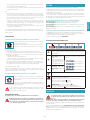
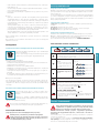
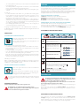
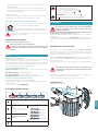
PULSANTIERA ELETTRONICA
Motore ON/OFF
All’avvio, la velocità è quella memorizzata al precedente spegnimento.
Incremento velocità da 1 a 4
Velocità 4 è attiva solo per alcuni
minuti, poi si attiva velocità 3.
Le velocità sono segnalate dai
led presenti nei tasti:
Velocità 1
Velocità 2
Velocità 3
Velocità 4
(led "+" lampeggiante)
Riduzione velocità da 4 a 1
Accensione / spegnimento luce
TIMER (Led rosso lampeggiante)
Autospegnimento dopo 15min.
La funzione si disattiva (Led rosso spento) se:
- Si preme un'altra volta il tasto TIMER ( ).
- Si preme il tasto ON/OFF ( ).
ALLARME FILTRI (Led rosso fisso con ( ) off)
Manutenzione filtri antigrasso dopo circa 30 ore di utilizzo.
Premere ( ) per 3 secondi per azzerare il contatore.
MANUTENZIONE
Prima di procedere a qualsiasi operazione di pulizia o di manu-
tenzione, disinserire l’apparecchio togliendo la spina o agendo
sull’interruttore generale.
Non si devono utilizzare detergenti contenenti sostanze abrasive, acide o
corrosive e panni con superci ruvide.
Una costante manutenzione garantisce un buon funzionamento e rendimento
nel tempo.
Particolari attenzioni vanno rivolte ai filtri metallici antigrasso: la pulizia fre-
quente dei filtri e dei loro supporti garantisce che non si accumulino grassi in-
fiammabili.
PULIZIA SUPERFICI ESTERNE
Si raccomanda di pulire le superfici esterne della cappa almeno ogni 15 giorni
per evitare che le sostanze oleose o grasse possano intaccarle. Per la pulizia della
cappa, realizzata in acciaio inox spazzolato, il Costruttore consiglia l'utilizzo delle
salviette "Magic Steel" che si possono anche ordinare on-line sul sito www.e-fal-
mec.com.
In alternativa e per tutti gli altri tipi di superci, la pulizia va eseguita usando
un panno umido leggermente imbevuto di detersivo neutro liquido o con alcool
denaturato.
Terminare la pulizia con un accurato risciacquo e asciugatura con panni morbidi.
Non utilizzare troppa acqua in prossimità della pulsantiera e dei
dispositivi di illuminazione per evitare che l'umidità raggiunga
parti elettroniche.
La pulizia dei pannelli in vetro va eseguita solo con detergenti specifici non cor-
rosivi o abrasivi utilizzando un panno morbido.
Il Costruttore declina ogni responsabilità qualora non vengano rispettate tali
istruzioni.

12
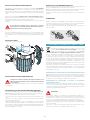
PULIZIA VETRI
Per togliere i vetri, vedi fi gura.
4
1
2
3
x4
PULIZIA SUPERFICI INTERNE
E’ vietata la pulizia di parti elettriche o parti relative al motore
all’interno della cappa, con liquidi o solventi.
Per le parti metalliche interne vedi paragrafo precedente.
FILTRI METALLICI ANTIGRASSO
Si consiglia di lavare frequentemente i fi ltri metallici (almeno ogni mese) la-
sciandoli in ammollo per circa 1 ora in acqua bollente con detersivo per piatti,
evitando di piegarli.
Non usare detergenti corrosivi, acidi o alcalini.
Risciacquarli con cura ed attendere che siano ben asciutti prima di rimontarli.
Il lavaggio in lavastoviglie è permesso, ma potrebbe creare imbrunimenti al
materiale dei fi ltri: per ridurre questo inconveniente utilizzare lavaggi a basse
temperature (55°C max.).
Per l’estrazione e l'inserimento dei fi ltri metallici antigrasso vedi istruzioni di
montaggio.
FILTRI AL CARBONE ATTIVO
Questi fi ltri trattengono gli odori presenti nell’aria che li attraversa. L’aria depura-
ta viene così rimessa nell’ambiente.
I fi ltri al carbone attivo devono essere sostituiti mediamente ogni 3-4 mesi in
condizioni di utilizzo normale.
Per la sostituzione dei fi ltri al carbone attivo vedi istruzioni di montaggio.
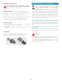
ILLUMINAZIONE
La cappa è dotata di illuminazione tramite faretti led ad alta effi cienza, basso
consumo e durata molto elevata in condizioni di normale utilizzo.
Nel caso si rendesse necessaria la sostituzione del faretto procedere come in
fi gura.
12V
3
1
2
SMALTIMENTO A FINE VITA
Il simbolo del cestino barrato riportato sull’apparecchiatura in suo pos-
sesso indica che il prodotto è un RAEE, cioè un “Rifi uto derivante dal-
le Apparecchiature Elettriche ed Elettroniche” e pertanto non deve
essere gettato nella spazzatura indi erenziata (cioè insieme ai “rifi uti urbani
misti”), ma deve essere gestito separatamente così da essere sottoposto ad ap-
posite operazioni per il suo riutilizzo, oppure a uno specifi co trattamento, per ri-
muovere e smaltire in modo sicuro le eventuali sostanze dannose per l’ambiente
ed estrarre le materie prime che possono essere riciclate. Lo smaltimento corret-
to di questo prodotto contribuirà a salvare preziose risorse ed evitare potenziali
eff etti negativi per la salute umana e per l’ambiente, che potrebbero essere cau-
sati da uno smaltimento inappropriato dei rifi uti.
Vi preghiamo di contattare le autorità locali per ulteriori dettagli sul punto di
smaltimento designato più vicino. Potrebbero venire applicate delle penali per
lo smaltimento scorretto di questi rifi uti in conformità alla legislazione nazionale.
INFORMAZIONI SULLO SMALTIMENTO IN ITALIA
In Italia le apparecchiature RAEE devono perciò essere consegnate:
- ai Centri di Raccolta (chiamati anche isole ecologiche o piattaforme ecologi-
che) allestiti dai Comuni o dalle Società di igiene urbana (in molte località vie-
ne anche eff ettuato il servizio di ritiro a domicilio delle apparecchiature RAEE
ingombranti);
- al negozio presso il quale si acquista una nuova apparecchiatura, che è tenuto
a ritirarle gratuitamente (ritiro “uno contro uno”);
- ad un negozio qualunque*, che è tenuto a ritirarle gratuitamente e senza
obbligo di acquisto (ritiro “uno contro zero”).
In questo caso:
1) l’apparecchiatura RAEE, per poter essere riconsegnata, deve avere “piccolis-
sime dimensioni” (altezza, profondità e larghezza minori di 25 cm);
* 2) il negozio al quale viene riconsegnata l’apparecchiatura RAEE deve avere
una superfi cie di vendita superiore a 400 mq.
INFORMAZIONI SULLO SMALTIMENTO IN NAZIONI DELL'UNIONE EURO
PEA
La Direttiva comunitaria sulle apparecchiature RAEE è stata recepita in modo
diverso da ciascuna nazione, pertanto se si desidera smaltire questa apparec-
chiatura suggeriamo di contattare le autorità locali o il Rivenditore per chiedere
il metodo corretto di smaltimento.
INFORMAZIONI SULLO SMALTIMENTO IN NAZIONI NON APPARTENENTI
ALL'UNIONE EUROPEA
Il simbolo del cestino barrato è valido solamente nell’Unione Europea: se si de-
sidera smaltire questa apparecchiatura in altri Paesi suggeriamo di contattare le
autorità locali o il Rivenditore per chiedere il metodo corretto di smaltimento.
ATTENZIONE!
Il Costruttore si riserva il diritto di apportare modifi che alle apparecchiature in
qualsiasi momento e senza preavviso. La stampa, la traduzione e la riproduzione
anche parziale del presente manuale s’intendono vincolate dall’autorizzazione
del Costruttore.
Le informazioni tecniche, le rappresentazioni grafi che e le specifi che presenti in
questo manuale sono indicative e non divulgabili.
La lingua di stesura del manuale è l’italiano, il Costruttore non si rende responsa-
bile per eventuali errori di trascrizione o traduzione.

13
ENGLISH
SAFETY INSTRUCTIONS
AND WARNINGS
Installation operations are to be carried
out by skilled and qualied installers in ac-
cordance with the instructions in this booklet and
in compliance with the regulations in force.
DO NOT use the hood if the power supply cable
or other components are damaged: disconnect
the hood from the electrical power supply and con-
tact the Dealer or an authorised Servicing Dealer for
repairs.
Do not modify the electrical, mechanical or func-
tional structure of the equipment.
Do not personally try to carry out repairs or re-
placements. Interventions carried out by incom-
petent and unauthorised persons can cause seri-
ous damage to the unit or physical and personal
harm, not covered by the Manufacturer's warranty.
WARNINGS FOR THE INSTALLER
TECHNICAL SAFETY
Before installing the hood, check the integ-
rity and function of each part. Should
anomalies be noted, do not proceed with installa-
tion and contact the Dealer.
Do NOT install the hood if an aesthetic (or cos-
metic) defect has been detected. Put it back into
its original package and contact the dealer.
No claim can be made for aesthetic (or cosmetic)
defects once it has been installed.
During installation, always use personal protective
equipment (e.g.: Safety shoes) and adopt prudent
and proper conduct.
The installation kit (screws and plugs) supplied with the
hood is only to be used on masonry walls: in case of in-
stallation on walls of a different material, assess other in-
stallation options keeping in mind the type of wall sur-
face and the weight of the hood (indicated on page 2).
Keep in mind that installations with different types of
fastening systems from those supplied, or which are
not compliant, can cause electrical and mechanical
seal danger.
Do not install the hood outdoors and do not expose
it to atmospheric elements (rain, wind, etc.).
ELECTRICAL SAFETY
The electrical system to which the hood is
to be connected must be in accordance
with local standards and supplied with earthed
connection in compliance with safety regulations
in the country of use. It must also comply with Eu-
ropean standards regarding radio antistatic prop-
erties.
Before installing the hood, check that the electrical
mains power supply corresponds with what is report-
ed on the identification plate located inside the hood.
The socket used to connect the installed equipment
to the electrical power supply must be within reach:
otherwise, install a mains switch to disconnect the
hood when required.
Any changes to the electrical system must be carried
out by a qualified electrician.
The maximum length of the flue fastening screws
(supplied by the manufacturer) must be 13 mm. Use
of non-compliant screws with these instructions can
lead to danger of an electrical nature.
Do not try to solve the problem yourself in the event
of equipment malfunction, but contact the Dealer or
an authorised Servicing Department for repairs.
When installing the hood, disconnect the
equipment by removing the plug or switch-
ing o the main switch.
FUMES DISCHARGE SAFETY
Do no connect the equipment to discharge
pipes of fumes produced from combustion
(for example boilers, replaces, etc.).
Before installing the hood, ensure that all standards in
force regarding discharge of air out of the room have
been complied with.
USER WARNINGS
These warnings have been drawn up for
your personal safety and those of others.
You are therefore kindly asked to read the book-
let carefully in its entirety before using the or
cleaning the equipment.
The Manufacturer declines all responsibility for
any damage caused directly, or indirectly, to per-
sons, things and pets as a consequence of failing
to comply with the safety warnings indicated in
this booklet.
It is imperative that this instructions booklet is
kept together with the equipment for any future
consultation.
If the equipment is sold or transferred to another per-
son, make sure that the booklet is also supplied so
that the new user can be made aware of the hood's
operation and relative warnings.
After the stainless steel hood has been installed, it
will need to be cleaned to remove any residues re-
maining from the protection adhesive as well as any
grease and oil stains which, if not removed, can cause
irreversible damage to the hood surface. To properly
clean the unit, the manufacturer recommends using
the supplied moist wipes, which are also available
sold separately.
Insist on original spare parts.

14
INTENDED USE
The equipment is solely intended to be used to
extract fumes generated from cooking food in
non-professional domestic kitchens: any other
use is improper. Improper use can cause damage
to persons, things, pets and exempts the Manu-
facturer from any liability.
The equipment can be used by children over the age
of 8 and by persons with reduced physical, sensory
and mental abilities, or with no experience or knowl-
edge, as long as they do so under supervision or after
having received relative instructions regarding safe
use of the equipment and understanding of the dan-
gers connected to it.
Children are not to play with the equipment. Clean-
ing and maintenance by the user must not be carried
out by children without supervision.
USE AND CLEANING WARNINGS
Before cleaning or carrying out mainte-
nance operations, disconnect the equip-
ment by removing the plug or switching o the
main switch.
Do not use the hood with wet hands or bare feet.
Always check that all electrical parts (lights, extractor
fan) are off when the equipment is not being used.
The maximum overall weight of any objects placed
or hung (if applicable) on the hood must not exceed
1.5 Kg.
Always supervise the cooking process during the use
of deep-fryers: Overheated oil can catch fire.
Do not leave open, unattended flames under the
hood.
Do not prepare food over an open flame under the
hood.
Never use the hood without the metal anti-grease
filters: in this case, grease and dirt will deposit in the
equipment and compromise its operation.
Accessible parts of the hood can be hot when used at
the same time as the cooking appliances.
Do not carry out any cleaning operations when parts
of the hood are still hot.
There can be a risk of fire if cleaning is not carried out
according to the instructions and products indicated
in this booklet.
Disconnect the main switch when the equipment is
not used for long periods of time.
If other appliances that use gas or other fu-
els are being used at the same time (boiler,
stove, replaces, etc.), make sure the room where
the fumes are discharged is well-ventilated, in
compliance with the local regulations.
INSTALLATION
only intended for personnel qualied
Before installing the hood, carefully read the chapter 'SAFETY
INSTRUCTIONS AND WARNINGS'.
TECHNICAL FEATURES
The technical specifications are exhibited on the labels located inside the hood.
POSITIONING
The minimum distance between the highest part of the cooking equip-
ment and the lowest part of the hood is indicated in the installation in-
structions.
Generally, when the hood is placed over gas cookers, the distance must be
at least 65 cm (25.6''). However, according to an interpretation of standard
EN60335-2-31 dated 11-07-2002 of TC61 (sub-clause 7.12.1 meeting 15 agenda
item 10.11), the minimum distance between the cooker and lower part of the
hood can be reduced to the quota reported in the installation instructions.
Should the instructions for the gas cooker specify a greater distance, this must
be taken into consideration.
Do not install the hood outdoors and do not expose it to outdoor environment
(rain, wind, etc.).
ELECTRICAL CONNECTION
(only intended for qualied personnel)
Disconnect the equipment from electrical mains power supply be-
fore carrying out any operations on the hood.
Ensure that the wires inside the hood are not disconnected or cut:
in the event of damage, contact your nearest Servicing Department.
Refer to qualied personnel for electrical connections.
Connection must be carried out in compliance with the provisions of law
in force.
Before connecting the hood to the electrical mains power supply, check that:
• voltage supply corresponds with what is reported on the data plate located
inside the hood;
• the electrical system is compliant and can withstand the load (see the techni-
cal specifications located inside the hood);
• the power supply plug and cable do not come into contact with tempera-
tures exceeding 70 °C;
• the power supply system is effectively and properly connected to earth in
compliance with regulations in force;
• the socket used to connect the hood is within reach.
In case of:
• devices fitted with cables without a plug: the type of plug to use is a ''stand-
ardised'' one. The wires must be connected as follows: yellow-green for earth-
ing, blue for neutral and brown for the phase. The plug must be connected to
an adequate safety socket.
• fixed equipment not provided with a power supply cable and plug, or any
other device that ensures disconnection from the electrical mains, with an
opening gap of the contacts that enables total disconnection in overvoltage
category III conditions.
Said disconnection devices must be provided in the mains power supply in
compliance with installation regulations.
The yellow/green earth cable must not be cut off by the switch.
The Manufacturer declines all responsibility for failure to comply with the safety
regulations.
FUMES DISCHARGE
EXTERNAL EXHAUST HOOD SUCTION
In this version the fumes and vapours are discharged outside
through the exhaust pipe.
To this end, the hood outlet fitting must be connected via a
pipe, to an external output.
The outlet pipe must have:
• a diameter not less than that of the hood fitting.
• a slight slope downwards (drop) in the horizontal sections to prevent conden-
sation from flowing back into the motor.

15
ENGLISH
• the minimum required number of bends.
• the minimum required length to avoid vibrations and reduce the suction per-
formance of the hood.
You are required to insulate the pipes if it passes through cold environments.
In the presence of motors with 800m3/h or higher, a check valve is present to
prevent external air fl owing back.
Deviation for Germany:
when the kitchen hood is used at the same time as appliances that are powered by
energy other than electricity, the negative pressure in the room must not exceed 4 Pa
(4 x 10⁻⁵ bar).
HOOD WITH INTERNAL RECIRCULATION FILTERING
In this model, the air passes through the charcoal fi lters to be
purifi ed and recycled in the environment.
Ensure that the active carbon fi lters are assembled into the
hood, if not, install them as indicated in the assembly instruc-
tions.
In this version the check valve must not be assembled: remove it if it is
on the air outlet fi tting of the motor.
ASSEMBLY INSTRUCTIONS
only intended for personnel quali ed
The hood can be installed in various con gurations.
The generic assembly steps apply to all installations; for each case,
follow the speci c steps provided for the required installation.
OPERATION
WHEN TO TURN ON THE HOOD?
Switch on the hood at least one minute before starting to cook to direct fumes
and vapours towards the suction surface.
After cooking, leave the hood operating until complete extraction of all vapours
and odours. By means of the Timer function, it is possible to set auto switch-off
function which will allow the hood to turn off automatically after 15 minutes of
operation.
WHICH SPEED IS TO BE SELECTED?
1st speed: maintains the circulation of clean air with low electricity consump-
tion.
2nd speed: normal conditions of use.
3rd speed: presence of strong odours and vapours.
4th speed: rapid disposal of odours and vapours.
WHEN SHOULD THE FILTERS BE WASHED OR REPLACED?
The metal fi lters must be cleaned every 30 hours of operation.
The active carbon fi lters must be replaced every 3-4 months, depending on the
use of the hood.
For further details see the “MAINTENANCE” chap.
ELECTRONIC PUSHBUTTON PANEL
Motor ON/OFF
Upon start-up, the speed is that stored at the previous operation.
Increase speed from 1 to 4
Speed 4 is only active for a few
minutes, then speed 3 activates.
The speeds are indicated by the
LEDs on the keys:
Speed 1
Speed 2
Speed 3
Speed 4
("+" LED fl ashing)
Reduce speed from 4 to 1
Light on/o
TIMER (red LED fl ashing)
Auto switch-off after 15 min.
The function deactivates (red LED off ) if:
- The TIMER key ( ) is pressed again.
- The ON/OFF key ( ) is pressed.
FILTER ALARM (red LED steady on with ( ) off )
Anti-grease fi lter maintenance after approximately 30 hours of op-
eration.
Press ( ) the meter for 3 seconds to reset.
MAINTENANCE
Before cleaning or carrying out maintenance operations, discon-
nect the equipment by removing the plug or switching o the
main switch.
Do not use detergents containing abrasive, acidic or corrosive substances
or abrasive cloths.
Regular maintenance guarantees proper operation and performance over time.
Special attention is to be paid to the metal anti-grease lters: frequent clean-
ing of the fi lters and their supports ensures that no fl ammable grease is accu-
mulated.
CLEANING OF EXTERNAL SURFACES
You are advised to clean the external surfaces of the hood at least once every
15 days to prevent oily substances and grease from sticking to them. To clean
the brushed stainless steel hood, the Manufacturer recommends using "Magic
Steel" wipes.
Alternatively and for all the other types of surfaces, it can be cleaned using a
damp cloth, slightly moistened with mild, liquid detergent or denatured alcohol.
Complete cleaning by rinsing well and drying with soft cloths.
Do not use too much moisture or water around the push button
control panel and lighting devices in order to prevent humidity
from reaching electronic parts.
The glass panels can only be cleaned with specifi c, non-corrosive or non-abra-
sive detergents using a soft cloth.
The Manufacturer declines all responsibility for failure to comply with these in-
structions.
GLASS CLEANING
To remove the glass, see fi gure.
4
1
2
3
x4

16
CLEANING OF INTERNAL SURFACES
Do not clean electrical parts, or parts related to the motor inside
the hood, with liquids or solvents.
For the internal metal parts, see the previous paragraph.
METAL ANTI-GREASE FILTERS
It is advised to frequently wash the metal filters (at least once a month) leaving
them to soak in boiling water and cleaning solution for 1 hour, taking care not
to bend them.
Do not use corrosive, acid or alkaline detergents.
Rinse them well and wait for them to be completely dry before reassembling
them.
Washing in a dishwasher is permitted, however, it may cause the filter material to
darken: to reduce the possibility of this problem from happening, use low-tem-
perature washes (55°C max.).
To extract and insert the metal anti-grease filters see the assembly instructions.
ACTIVE CARBON FILTERS
These filters retain the odours in the air that passes through them. The purified
air is recirculated into the environment.
The active carbon filters must be replaced on average every 3-4 months under
normal conditions of use.
See assembly instructions to replace the active carbon filters.
LIGHTING
The range hood is equipped with high efficiency, low consumption LED spot-
lights with an extremely long life-span under normal use conditions.
Should the LED spotlight need to be replaced, proceed as shown in the figure.
12V
3
1
2
DISPOSAL AFTER END OF USEFUL LIFE
The crossed-out trash or refuse bin symbol on the appliance means
that the product is WEEE, i.e. “Waste electrical and electronic equip-
ment'', accordingly it must not be disposed of with regular unsort-
ed waste (i.e. with ''mixed household waste''), but it must be disposed of sepa-
rately so that it can undergo specific processing for its re-use, or a specific
treatment, to remove and safely dispose of any substances that may be harmful
to the environment and remove the raw materials that can be recycled. Proper
disposal of these products contributes to saving valuable resources and avoid
potential negative effects on personal health and the environment, which may
be caused by inappropriate disposal of waste.
You are kindly asked to contact your local authorities for further information
regarding the designated waste collection points nearest to you. Penalties for
improper disposal of such waste can be applied in compliance with national
regulations.
INFORMATION ON DISPOSAL IN EUROPEAN UNION COUNTRIES
The EU WEEE Directive was implemented differently in each country, accord-
ingly, if you wish to dispose of this appliance we suggest contacting your local
authorities or dealer to find out what the correct method of disposal is.
INFORMATION ON DISPOSAL IN NONEUROPEAN UNION COUNTRIES
The crossed-out trash or refuse bin symbol is only valid in the European Union: if
you wish to dispose of this appliance in other countries, we suggest contacting
your local authorities or dealer to find out what the correct method of disposal is.
WARNING!
The Manufacturer reserves the right to make changes to the equipment at any
time and without prior notice. Printing, translation and reproduction, even par-
tial, of this manual are bound by the Manufacturer's authorisation.
Technical information, graphic representations and specifications in this manual
are for information purposes and cannot be divulged.
This manual is written in Italian. The Manufacturer is not responsible for any tran-
scription or translation errors.

17
DEUTSCH
ANWEISUNGEN FÜR DIE SICHERHEIT
UND WARNHINWEISE
Die Installation muss von kompetenten und
qualizierten Installateuren unter Befolgung
der Angaben der vorliegenden Gebrauchsanweisung
sowie unter Einhaltung der gültigen Sicherheitsvor
-
schriften vorgenommen werden.
Wenn das Versorgungskabel oder andere Komponen
-
ten beschädigt sind, darf die Abzugshaube NICHT
verwendet werden:
Die Abzugshaube von der Strom-
versorgung trennen und den Händler oder den auto-
risierten Kundendienst für die Reparatur kontaktieren.
Die elektrische, mechanische und funktionelle Struktur
des Geräts darf nicht verändert werden.
Niemals versuchen, Reparaturen oder Austauschtätig-
keiten selbst durchzuführen. Werden diese Arbeiten von
Personen durchgeführt, die nicht dazu befähigt und qua
-
liziert sind, so kann dies zu schweren Personen- und
Sachschäden führen, die von der Herstellergarantie nicht
gedeckt sind.
HINWEISE FÜR DEN INSTALLATEUR
TECHNISCHE SICHERHEIT
Vor der Installation der Abzugshaube muss sicher-
gestellt werden, dass sämtliche Komponenten un-
beschädigt und funktionstüchtig sind. Sollten Schäden
festgestellt werden, nicht mit der Installation fortfahren
und umgehend den Händler kontaktieren.
Sollte ein ästhetischer Mangel festgestellt werden, so
darf die Abzugshaube NICHT installiert werden. Die
Abzugshaube wieder verpacken und umgehend den
Händler kontaktieren.
Sobald die Abzugshaube installiert ist, werden keine
Beanstandungen aufgrund ästhetischer Mängel mehr
akzeptiert.
Während der Installation ist immer eine geeignete
persönliche Schutzausrüstung zu tragen (z.B. Sicher-
heitsschuhwerk) und aufmerksam und korrekt vorzu-
gehen.
Das mit der Abzugshaube gelieferte Befestigungs-
set (Schrauben und Dübel) darf ausschließlich für
gemauerte Wände verwendet werden. Sollte es not-
wendig sein, die Abzugshaube an einer Wand aus
anderem Material zu installieren, müssen alternative
Befestigungssysteme in Betracht gezogen werden,
wobei die Festigkeit der Wand und das Gewicht der
Abzugshaube (siehe S. 2) zu berücksichtigen sind.
Dabei ist zu beachten, dass die Installation mit Befes-
tigungssystemen, die von den mitgelieferten abwei-
chen, elektrische Gefahren und Risiken in Bezug auf
die mechanische Abdichtung mit sich bringen kann.
Die Abzugshaube darf nicht in Außenbereichen in-
stalliert und keinen Witterungseinflüssen (Regen,
Wind, etc.) ausgesetzt werden.
ELEKTRISCHE SICHERHEIT
Die elektrische Anlage für den Anschluss
der Abzugshaube muss den geltenden
Normen entsprechen und mit einem Erdungssys-
tem ausgestattet sein, das den Sicherheitsvor-
schriften des Installationslandes entspricht. Sie
muss außerdem der EU-Gesetzgebung bezüglich
der Funkentstörung entsprechen.
Vor der Installation der Abzugshaube muss überprüft
werden, dass die Netzspannung derjenigen auf dem
Typenschild im Inneren der Abzugshaube entspricht.
Die für den elektrischen Anschluss verwendete Steck-
dose muss gut erreichbar sein, wenn das Gerät ins-
talliert ist. Andernfalls muss ein Hauptschalter vorge-
sehen werden, um die Abzugshaube bei Bedarf zu
trennen.
Sämtliche eventuellen Änderungen an der Elektroan-
lage müssen von einem qualifizierten Elektriker vor-
genommen werden.
Die Mindestlänge der Befestigungsschraube des Ka-
mins (vom Hersteller mitgeliefert) beträgt 13 mm. Die
Verwendung von Schrauben, die der vorliegenden
Gebrauchsanweisung nicht entsprechen, kann elek-
trische Gefahren mit sich bringen.
Im Fall einer Störung des Geräts nicht versuchen, das
Problem eigenständig zu lösen, sondern den Händler
oder den autorisierten Kundendienst für die Repara-
tur kontaktieren.
Während der Installation der Abzugshaube muss
das Gerät durch Ziehen des Netzsteckers oder
Betätigung des Hauptschalters abgeschaltet werden.
SICHERHEIT RAUCHABZUG
Das Gerät nicht an Rohre für den Abzug von
Rauch anschließen, der durch Verbrennung ent
-
steht (z.B. Heizkessel, Kamine, etc.).
Vor der Installation der Abzugshaube muss sicher-
gestellt werden, dass alle gültigen gesetzlichen Vor-
schriften in Bezug auf die Luftableitung aus dem
Raum eingehalten werden.
HINWEISE FÜR DEN BENUTZER
Diese Hinweise wurden für Ihre Sicherheit und
die Sicherheit anderer Personen erstellt, und
wir bitten Sie deshalb, die vorliegende Gebrauchsan
-
weisung vor der Installation, der Verwendung oder der
Reinigung des Geräts vollständig zu lesen.
Der Hersteller lehnt jegliche Haftung für etwaige di
-
rekte oder indirekte Schäden von Personen, Gegen-
ständen oder Haustieren ab, die durch eine Nichtbe-
achtung der in der vorliegenden Gebrauchsanweisung
angeführten Sicherheitshinweise verursacht werden.
Es ist sehr wichtig, dass diese Gebrauchsanweisung zu
-
sammen mit dem Gerät aufbewahrt wird, damit künf-
tig darin nachgelesen werden kann.

18
Falls das Gerät verkauft oder an eine andere Person
übergeben wird, muss sichergestellt werden, dass
auch die Gebrauchsanweisung übergeben wird, da-
mit der neue Besitzer informiert werden kann, wie die
Abzugshaube funktioniert und welche diesbezügli-
chen Warnhinweise zu beachten sind.
Nach der Installation der Edelstahlhaube muss als Ers-
tes deren Reinigung erfolgen, um die Rückstände der
Schutzklebefolie und eventuelle Flecken von Öl oder
Fett zu entfernen, die die Oberfläche der Abzugshau-
be unwiderruflich beschädigen können, falls sie nicht
entfernt werden. Für diesen Vorgang empfiehlt der
Hersteller, die mitgelieferten Reinigungstücher zu be-
nutzen, die auch gekauft werden können.
Immer die Verwendung von originalen Ersatzteilen
fordern.
VERWENDUNGSBESTIMMUNG
Das Gerät ist ausschließlich für die Absaugung von
Rauch bestimmt, der während der Zubereitung von
Speisen in Haushaltsküchen, nicht in gewerblichen
Küchen, erzeugt wird. Jede andere Verwendung gilt
als unsachgemäß, kann Schäden an Personen, Gegen
-
ständen und Haustieren verursachen und enthebt den
Hersteller von jeglicher Verantwortung.
Dieses Gerät kann von Kindern ab 8 Jahren sowie von
Personen mit reduzierten physischen, sensorischen
oder mentalen Fähigkeiten oder Mangel an Erfah-
rung und/oder Wissen benutzt werden, wenn sie
beaufsichtigt oder bezüglich des sicheren Gebrauchs
des Gerätes unterwiesen wurden und die damit zu-
sammenhängenden Gefahren verstanden haben.
Kinder dürfen nicht mit dem Gerät spielen. Kinder
dürfen die vom Benutzer auszuführende Reinigung
und Wartung nicht unbeaufsichtigt durchführen.
HINWEISE FÜR VERWENDUNG UND REINIGUNG
Vor jedem Reinigungs- oder Wartungseingri
das Gerät durch Ziehen des Netzsteckers oder
Betätigung des Hauptschalters vom Stromnetz tren
-
nen.
Die Abzugshaube nicht mit nassen Händen oder
nackten Füßen verwenden.
Immer kontrollieren, dass alle elektrischen Teile (Be-
leuchtung, Absauganlage) ausgeschaltet sind, wenn
das Gerät nicht verwendet wird.
Das maximale Gesamtgewicht eventuell auf der Ab-
zugshaube abgestellter oder an ihr aufgehängter Ge-
genstände (falls vorgesehen) darf 1,5 kg nicht über-
schreiten.
Fritteusen müssen während des Betriebs überwacht
werden: Das erhitzte Öl könnte Feuer fangen.
Unter der Haube keine offenen Flammen verwenden.
Unterhalb der Abzugshaube keine Garvorgänge mit
"offenen" Flammen ausführen.
Die Abzugshaube nie ohne Metallfettfilter verwen-
den. In diesem Fall würden sich Fett und Schmutz auf
dem Gerät absetzen und seine Funktionstüchtigkeit
beeinträchtigen.
Die erreichbaren Teile der Abzugshaube können heiß
sein, wenn sie zusammen mit Kochgeräten verwen-
det werden.
Mit der Reinigung so lange warten, bis alle Teile der
Abzugshaube abgekühlt sind.
Sollte die Reinigung nicht gemäß den Vorschriften
und mit den Produkten ausgeführt werden, die im
vorliegenden Handbuch angegeben sind, so besteht
Brandgefahr.
Wenn das Gerät über einen längeren Zeitraum nicht
verwendet wird, muss der Hauptschalter abgeschal-
tet werden.
Bei gleichzeitiger Verwendung anderer mit Gas
oder anderen Brennstoen gespeister Verbrau
-
cher (Heizkessel, Öfen, Kamine, etc.) für eine angemes-
sene, vorschriftsmäßige Lüftung des Raumes sorgen,
in dem die Dunstabsaugung erfolgt.
INSTALLATION
Dieser Abschnitt ist ausschließlich qualiziertem Personal vorbehalten
Vor der Installation der Abzugshaube muss das Kapitel "ANWEISUNGEN
FÜR DIE SICHERHEIT UND WARNHINWEISE" aufmerksam gelesen wer-
den.
TECHNISCHE MERKMALE
Die technischen Daten des Geräts sind auf den Schildern im Inneren der Abzugs-
haube angegeben.
POSITIONIERUNG
Der Mindestabstand zwischen dem höchsten Teil des Kochgeräts und dem
untersten Teil der Abzugshaube ist in der Montageanleitung angegeben.
Wenn die Abzugshaube über einer Gaskochfläche positioniert ist, muss dieser
Abstand gewöhnlich mindestens 65 cm (25,6") betragen. Dennoch kann gemäß
der Auslegung der Norm EN60335-2-31 vom 11.07.2002 vonseiten der TC61
(subclause 7.12.1 meeting 15 agenda item 10.11) der Mindestabstand zwischen
der Kochebene und dem unteren Teil der Abzugshaube auf den in der Monta-
geanleitung angegebenen Wert vermindert werden.
Wenn die Anleitung der Gaskochebene einen größeren Abstand vorschreibt,
muss dies eingehalten werden.
Die Abzugshaube darf nicht in Außenbereichen installiert und keinen Witte-
rungseinflüssen (Regen, Wind, etc.) ausgesetzt werden.
ELEKTRISCHER ANSCHLUSS
(Dieser Abschnitt ist ausschließlich qualiziertem Personal vorbehalten)
Vor sämtlichen Eingrien an der Abzugshaube muss das Gerät
vom Stromnetz getrennt werden.
Sicherstellen, dass die Elektrokabel in der Abzugshaube nicht ab-
geschnitten oder getrennt werden:
Andernfalls muss das nächstgelegene Kundendienstzentrum kontaktiert
werden. Für die elektrischen Anschlüsse qualiziertes Personal beauftra-
gen. Der Anschluss muss in Übereinstimmung mit der geltenden Gesetz-
gebung ausgeführt werden.
Bevor das Gerät ans Stromnetz angeschlossen wird, muss geprüft werden, dass:
• die Netzspannung jener der Daten auf dem Typenschild in der Abzugshaube
entspricht;
• die elektrische Anlage den gesetzlichen Vorschriften entspricht und für die
Belastung des Geräts geeignet ist (siehe Kenndaten in der Abzugshaube);
• der Stecker und das Kabel nicht mit heißen Komponenten mit Temperaturen
über 70 °C in Berührung kommen;

19
DEUTSCH
• die Versorgungsanlage mit einer wirksamen und gemäß den geltenden Nor-
men ausgeführten Erdung verbunden ist;
• die für den Anschluss verwendete Steckdose gut erreichbar ist, wenn die Ab-
zugshaube installiert ist.
Bei:
• mit einem Kabel ohne Stecker ausgestatteten Geräten: muss der zu verwen-
dende Stecker ein genormter Stecker sein. Die Kabel müssen wie folgt an-
geschlossen werden: Das gelb-grüne Kabel für die Erdung, das blaue Kabel
für den Nullleiter und das braune für die Phase. Der Stecker muss an einer
geeigneten Sicherheitssteckdose angeschlossen werden.
• einem fest montierten Gerät, das über kein Versorgungskabel oder eine
andere Vorrichtung zur Trennung vom Stromnetz mit einer derartigen Öff-
nungsdistanz der Kontakte verfügt, dass die vollständige Trennung zu den
Bedingungen der Überspannungskategorie III erfolgt.
Diese Trennvorrichtungen müssen gemäß den Installationsnormen am Ver-
sorgungsnetz installiert werden.
Der grün/gelbe Erdungsdraht darf nicht vom Schalter unterbrochen werden.
Der Hersteller lehnt jede Haftung ab, falls die Sicherheitsnormen nicht einge-
halten werden.
RAUCHABZUG
ABZUGSHAUBE IN VERSION AUSSENABLUFT ABLUFTVERSION
Bei dieser Ausführung werden die Dämpfe über ein Abzugs-
rohr nach außen abgeleitet.
Deshalb muss der Anschluss der Haube für den Abzug mit ei-
nem Rohr an einem externen Abzug angeschlossen werden.
Das Abzugsrohr muss:
• einen größeren Durchmesser als der Abzugshaubenanschluss haben.
• in den horizontalen Abschnitten eine leichte Neigung nach unten aufweisen
(Gefälle), um zu verhindern, dass das entstehende Kondenswasser in die Ab-
zugshaube zurückfließt.
• so wenig Kurven wie möglich aufweisen.
• so kurz wie möglich sein, um Vibrationen zu vermeiden, und um zu verhin-
dern, dass die Abzugsleistung der Haube reduziert wird.
Wenn die Rohrleitung durch kalte Räume verläuft, muss sie isoliert werden.
Um ein Rückströmen der Luft von Außen zu vermeiden, verfügen Abzugshau-
ben mit Motoren zu 800m3/h oder mehr, über ein Rückschlagventil.
Abweichungen für Deutschland:
Wenn die Herdabzugshaube gleichzeitig mit Geräten betrieben wird, die mit einer
anderen Energie als elektrischem Strom betrieben werden, darf der negative Druck im
Raum 4 Pa nicht überschreiten (4 x 10⁻⁵ bar).
ABZUGSHAUBE IN VERSION INNENUMLUFT FILTRIEREND
In dieser Ausführung strömt die Luft durch die Aktivkohlefil-
ter, wo sie gereinigt wird, und wird anschließend in den Raum
zurückgeleitet.
Kontrollieren, dass die Aktivkohlefilter in der Abzugshaube an-
gebracht sind, andernfalls müssen sie angebracht werden, wie
in der Montageanleitung angeführt.
In dieser Ausführung darf das Rückschlagventil nicht montiert werden.
Sollte es dennoch am Anschluss für den Luftabzug des Motors vorhan-
den sein, muss es entfernt werden.
MONTAGEANLEITUNG
Dieser Abschnitt ist ausschließlich qualiziertem Personal vorbehalten
Die Abzugshaube kann in verschiedenen Kongurationen installiert wer-
den: Die allgemeinen Montagephasen gelten für alle Installationen; befol-
gen Sie dagegen die entsprechenden Phasen der gewünschten Installati-
on, wo dies extra angegeben wird.
BETRIEB
WANN MUSS DIE ABZUGSHAUBE EINGESCHALTET WERDEN?
Die Abzugshaube mindestens eine Minute vor Beginn des Kochvorgangs ein-
schalten. Dadurch wird ein Luftstrom erzeugt, der den Rauch und die Dämpfe
zur Absaugfläche hin befördert.
Nach Abschluss des Kochvorgangs die Abzugshaube noch so lange laufen las-
sen, bis alle Dämpfe und Gerüche abgesaugt sind. Es besteht eventuell auch
die Möglichkeit, mit Hilfe der Timer-Funktion die automatische Abschaltung der
Abzugshaube nach 15 Minuten Betrieb einzustellen.
WELCHE GESCHWINDIGKEITSSTUFE SOLL GEWÄHLT WERDEN?
Geschwindigkeit 1: Hält die Luft bei geringem Stromverbrauch rein.
Geschwindigkeit 2: Wird für normale Bedingungen verwendet.
Geschwindigkeit 3: Wird bei Vorhandensein von starken Gerüchen oder Dämp-
fen verwendet.
Geschwindigkeit 4: Wird für eine schnelle Beseitigung von Gerüchen oder
Dämpfen verwendet.
WANN MÜSSEN DIE FILTER GEREINIGT ODER AUSGETAUSCHT WERDEN?
Die Metallfilter müssen jeweils nach 30 Betriebsstunden gereinigt werden.
Die Aktivkohlefilter müssen im Durchschnitt alle 3-4 Monate, je nachdem, wie
oft die Abzugshaube verwendet wird, ausgetauscht werden.
Für weitere Details siehe Kapitel “WARTUNG”.
ELEKTRONISCHE DRUCKKNOPFTAFEL
Motor ON/OFF
Der Start erfolgt mit der vor dem Ausschalten gespeicherten Ge-
schwindigkeit.
Erhöhung der Ge-
schwindigkeit von 1
bis 4
Die Geschwindigkeit 4 ist
nur für einige Minuten ak-
tiviert, dann wird die Ge-
schwindigkeit 3 aktiviert.
Die Geschwindigkeiten werden von den
an den Tasten vorhandenen LEDs signa-
lisiert:
Geschwindigkeit 1
Geschwindigkeit 2
Geschwindigkeit 3
Geschwindigkeit 4
(LED "+" blinkend)
Drosselung der Ge-
schwindigkeit von 4
bis 1
Einschalten / Ausschalten des Lichts
TIMER
(rote blinkende LED)
Selbstausschaltung nach 15 Minuten
Die Funktion wird deaktiviert (rote LED ausgeschaltet), wenn:
- man erneut die Taste TIMER ( ) drückt.
- wenn man die Taste ON/OFF ( ) drückt.
ALARM FILTER
(rote LED dauerhaft mit ( ) off)
Wartung der Fettfilter nach ungefähr 30 Betriebsstunden.
3 Sekunden lang drücken ( ), um den Zähler auf Null zu stellen.
WARTUNG
Vor jedem Reinigungs- oder Wartungseingri das Gerät durch Ziehen
des Netzsteckers oder Betätigung des Hauptschalters vom Stromnetz
trennen.
Es dürfen keine Tücher mit rauer Oberäche oder Reinigungsmittel verwendet
werden, die scheuernde, säurehältige oder korrosive Substanzen enthalten
.
Eine kontinuierliche Wartung gewährleistet langfristig einen guten Betrieb und
eine gute Leistung.
Besondere Aufmerksamkeit muss den Metallfettltern und den Aktivkohlel-
tern geschenkt werden: eine häufige Reinigung der Filter und ihrer Halterungen
gewährleistet, dass sich an der Abzugshaube kein Fett ablagert, das leicht ent-
zündlich und somit gefährlich ist.

20
REINIGUNG DER AUSSENFLÄCHEN
Es wird empfohlen, die Außenfl ächen der Abzugshaube mindestens alle 2
Wochen zu reinigen, um zu vermeiden, dass ölige und fettige Substanzen die
Stahloberfl ächen angreifen. Für die Reinigung der Abzugshaube aus gebürste-
tem Edelstahl empfi ehlt der Hersteller die Verwendung der Reinigungstücher
"Magic Steel".
Alternativ dazu und für alle anderen Arten von Ober ächen muss die Rei-
nigung mit einem feuchten Lappen mit neutralem Reinigungsmittel oder mit
denaturiertem Alkohol ausgeführt werden.
Am Ende der Reinigung die Abzugshaube mit weichen Tüchern sorgfältig abwi-
schen und abtrocknen.
Im Bereich der Bedientafel und der Beleuchtungsvorrichtungen nur we-
nig Wasser verwenden, um zu vermeiden, dass die elektronischen Bau-
teile feucht werden.
Die Reinigung der Glasplatten darf nur mit spezifi schen nicht korrosiven oder
scheuernden Reinigungsmitteln mit einem weichen Tuch ausgeführt werden.
Der Hersteller lehnt jede Haftung ab, falls diese Anweisungen nicht befolgt wer-
den.
REINIGUNG DER GLASPLATTEN
Siehe Abbildung, um die Glasplatten zu entfernen.
4
1
2
3
x4
REINIGUNG DER INNENFLÄCHEN
Die Reinigung von elektrischen oder zum Motor gehörenden Tei-
len in der Abzugshaube mit Flüssigkeiten oder Lösungsmitteln
ist verboten.
Für die Metallteile siehe den vorigen Abschnitt.
METALLFETTFILTER
Deshalb wird empfohlen, die Metallfi lter häu g zu reinigen (mindestens ein
Mal pro Monat), indem sie ungefähr 1 Stunde lang in kochend heißem Wasser
mit Geschirrspülmittel eingeweicht werden. Darauf achten, sie nicht zu biegen.
Keine korrosiven, säurehältigen oder alkalischen Reinigungsmittel verwenden.
Die Metallfi lter sorgfältig abspülen und vor der Montage abwarten, bis sie voll-
ständig trocken sind.
Die Metallfi lter können auch in der Spülmaschine gereinigt werden, aber es
könnte zu einer Braunfärbung des Materials kommen. Um dies zu vermeiden,
einen Spülgang mit niedriger Temperatur (max. 55 °C) wählen.
Für die Montage und Demontage der Metallfettfi lter siehe die Montageanlei-
tung.
DIE AKTIV-KOHLEFILTER
Diese Filter halten die in der durchströmenden Luft vorhandenen Gerüche zu-
rück. Die gereinigte Luft wird somit erneut in den Raum zurückgeführt.
Die Aktivkohlefi lter müssen bei normalen Betriebsbedingungen im Durch-
schnitt alle 3-4 Monate ausgewechselt werden.
Für den Austausch der Aktivkohlefi lter siehe Einbauanleitung.
BELEUCHTUNG
Die Abzugshaube ist mit einer Beleuchtung mit hochleistungsfähigen LED-
Spots mit geringem Stromverbrauch und sehr langer Lebensdauer bei norma-
lem Gebrauch ausgestattet.
Sollte der LED-Spot ausgetauscht werden müssen, so ist wie in der Abbildung
vorzugehen.
12V
3
1
2
ENTSORGUNG AM ENDE DER LEBENSDAUER
Das Symbol der durchgestrichenen Abfalltonne auf Rädern auf Ihrem
Gerät bedeutet, dass es sich um ein
WEEE-Produkt handelt
, das somit
ein "Abfall aus elektrischen und elektronischen Geräten” ist. Darum
darf es nicht der ungetrennten Abfallentsorgung zugeführt werden (also
zusammen mit “unsortiertem Hausmüll” weggeworfen werden), sondern muss
getrennt verwaltet werden, um es entsprechenden Eingriff en für eine Wieder-
verwertung oder einer spezifi schen Behandlung zu unterziehen, damit die et-
waigen umweltgefährdenden Stoff e sicher entfernt und entsorgt werden und
die recycelfähigen Rohstoff e entnommen werden. Die sachgemäße Entsorgung
dieses Produktes trägt dazu bei, wertvolle Ressourcen zu schützen und potenti-
ell negative Auswirkungen auf die Gesundheit des Menschen und die Umwelt
zu vermeiden, die hingegen durch eine unsachgemäße Entsorgung dieser Ab-
fälle entstehen könnten.
Für weitere Informationen bezüglich der in Ihrer Nähe liegenden speziellen
Sammelstellen bitten wir Sie, die lokalen Behörden zu kontaktieren. Für eine un-
sachgemäße Entsorgung dieser Abfälle könnten in Übereinstimmung mit der
nationalen Gesetzgebung Strafen vorgesehen sein.
INFORMATIONEN ZUR ENTSORGUNG INNERHALB DER EUROPÄISCHEN
UNION
Die europäische Richtlinie zu den WEEE-Geräten wurden in jedem Land auf an-
dere Weise ausgelegt. Darum sollten bei der Entsorgung dieses Geräts die loka-
len Behörden oder der Händler kontaktiert werden, um sich über die korrekte
diesbezügliche Vorgehensweise zu informieren.
INFORMATIONEN ZUR ENTSORGUNG IN LÄNDERN AUSSERHALB DER
EUROPÄISCHEN UNION
Das Symbol der durchgestrichenen Abfalltonne auf Rädern ist nur in der Europä-
ischen Union gültig: Wenn das Gerät in anderen Ländern entsorgt werden soll,
sollten die lokalen Behörden oder der Händler kontaktiert werden, um sich über
die korrekte diesbezügliche Vorgehensweise zu informieren.
ACHTUNG!
Der Hersteller behält sich das Recht vor, jederzeit und ohne Vorankündigung
Änderungen an den Geräten vorzunehmen. Der Druck, die Übersetzung und
die - auch auszugsweise - Reproduktion des vorliegenden Handbuchs müssen
zuvor vom Hersteller genehmigt werden.
Die im vorliegenden Handbuch enthaltenen technischen Informationen, die
grafi schen Darstellungen sowie die Spezifi kationen dienen nur als Richtlinie und
dürfen nicht verbreitet werden.
Das Handbuch wurde in italienischer Sprache verfasst, der Hersteller übernimmt
keine Haftung für etwaige Transkriptions- oder Übersetzungsfehler.
La pagina sta caricando ...
La pagina sta caricando ...
La pagina sta caricando ...
La pagina sta caricando ...
La pagina sta caricando ...
La pagina sta caricando ...
La pagina sta caricando ...
La pagina sta caricando ...
La pagina sta caricando ...
La pagina sta caricando ...
La pagina sta caricando ...
La pagina sta caricando ...
La pagina sta caricando ...
La pagina sta caricando ...
La pagina sta caricando ...
La pagina sta caricando ...
La pagina sta caricando ...
La pagina sta caricando ...
La pagina sta caricando ...
La pagina sta caricando ...
La pagina sta caricando ...
La pagina sta caricando ...
La pagina sta caricando ...
La pagina sta caricando ...
La pagina sta caricando ...
La pagina sta caricando ...
La pagina sta caricando ...
La pagina sta caricando ...
La pagina sta caricando ...
La pagina sta caricando ...
La pagina sta caricando ...
La pagina sta caricando ...
La pagina sta caricando ...
La pagina sta caricando ...
La pagina sta caricando ...
La pagina sta caricando ...
La pagina sta caricando ...
La pagina sta caricando ...
La pagina sta caricando ...
La pagina sta caricando ...
La pagina sta caricando ...
La pagina sta caricando ...
La pagina sta caricando ...
La pagina sta caricando ...
-
 1
1
-
 2
2
-
 3
3
-
 4
4
-
 5
5
-
 6
6
-
 7
7
-
 8
8
-
 9
9
-
 10
10
-
 11
11
-
 12
12
-
 13
13
-
 14
14
-
 15
15
-
 16
16
-
 17
17
-
 18
18
-
 19
19
-
 20
20
-
 21
21
-
 22
22
-
 23
23
-
 24
24
-
 25
25
-
 26
26
-
 27
27
-
 28
28
-
 29
29
-
 30
30
-
 31
31
-
 32
32
-
 33
33
-
 34
34
-
 35
35
-
 36
36
-
 37
37
-
 38
38
-
 39
39
-
 40
40
-
 41
41
-
 42
42
-
 43
43
-
 44
44
-
 45
45
-
 46
46
-
 47
47
-
 48
48
-
 49
49
-
 50
50
-
 51
51
-
 52
52
-
 53
53
-
 54
54
-
 55
55
-
 56
56
-
 57
57
-
 58
58
-
 59
59
-
 60
60
-
 61
61
-
 62
62
-
 63
63
-
 64
64


Falmec FDPST26W5SG Manuale del proprietario
- Categoria
- Cappe da cucina
- Tipo
- Manuale del proprietario
- Questo manuale è adatto anche per
in altre lingue
- English: Falmec FDPST26W5SG Owner's manual
- français: Falmec FDPST26W5SG Le manuel du propriétaire
- español: Falmec FDPST26W5SG El manual del propietario
- Deutsch: Falmec FDPST26W5SG Bedienungsanleitung
- русский: Falmec FDPST26W5SG Инструкция по применению
- Nederlands: Falmec FDPST26W5SG de handleiding
- português: Falmec FDPST26W5SG Manual do proprietário
- dansk: Falmec FDPST26W5SG Brugervejledning
- polski: Falmec FDPST26W5SG Instrukcja obsługi
- svenska: Falmec FDPST26W5SG Bruksanvisning
- suomi: Falmec FDPST26W5SG Omistajan opas
Documenti correlati
-
Falmec FDQWH36W5SG Guida utente
-
-
-
-
-
Falmec Groove Manuale del proprietario
-
-
Falmec ZEPHIRO Manuale del proprietario
-