Falmec Astra Island Manuale del proprietario
- Categoria
- Cappe da cucina
- Tipo
- Manuale del proprietario
Questo manuale è adatto anche per

Cod. 110030252 (CAPPE AD ISOLA)
Ed. 2013
LIBRETTO ISTRUZIONI
INSTRUCTIONS BOOKLET
BEDIENUNGSSANLEITUNG
LIVRET D’INSTRUCTIONS
MANUAL DE INSTRUCCIONES
MANUAL DE INSTRUÇÕES
àçëíêìäñàü èé ùäëèãìÄíÄñàà
INSTRUKCJE OBSŁUGI
BRUKSANVISNING
INSTRUKTIONSMANUAL
KÄYTTÖOHJE
BRUKSANVISNING
Ed. 2014
Italiano English Deutsch Français Español Português
на русском
языке
Norsk
Polska
Svensk
Dansk Norsk
Suomi


1

2

3

4

5

6

7

8
I
LIBRETTO ISTRUZIONI
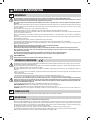
AVVERTENZE
A
È molto importante che questo libretto istruzioni sia conservato insieme all’apparecchiatura per qualsiasi futura consultazione.
Se l’apparecchio dovesse essere venduto o trasferito ad un’altra persona, assicurarsi che il libretto venga fornito assieme, in modo
che il nuovo utente possa essere messo al corrente del funzionamento della cappa e delle avvertenze relative.
Queste avvertenze sono state redatte per la vostra sicurezza e per quella degli altri, Vi preghiamo, dunque, di volerlo leggere attenta-
mente prima d’installare e di utilizzare l’apparecchio.
Il presente dispositivo non è stato progettato per essere utilizzato da persone (bambini inclusi) con ridotte capacità fisiche, sensoriali o
mentali, o prive di esperienza o conoscenze adeguate, a meno che non agiscano sotto la supervisione di una persona responsabile della
sicurezza o abbiano ricevuto istruzioni relativamente all’uso del dispositivo.
Occorre sorvegliare i bambini affinché non giochino con il dispositivo.
Il lavoro di installazione deve essere eseguito, da installatori competenti e qualificati, secondo le norme in vigore.
Se il cavo di alimentazione è danneggiato, esso deve essere sostituito dal costruttore o dal suo servizio assistenza tecnica o comunque
da una persona con qualifica similare, in modo da prevenire ogni rischio.
Ogni eventuale modifica che si rendesse necessaria all’impianto elettrico per installare la cappa dovrà essere eseguita solo da persone
competenti.
È pericoloso modificare o tentare di modificare le caratteristiche di questo impianto. In caso di riparazioni o mal funzionamento dell’ap-
parecchio, non tentare di risolvere da soli il problema.
Le riparazioni effettuate da persone non competenti possono provocare danni.
Per eventuali interventi rivolgersi ad un Centro Assistenza Tecnica autorizzato ad eseguire parti di ricambio.
Controllare sempre che tutte le parti elettriche, (luci, aspiratore), siano spente quando l’apparecchio non viene usato. Leggere tutto il
libretto istruzioni prima di effettuare operazioni sulla cappa.
L’utilizzo della cappa non può essere diverso da quello di aspiratori di fumi di cottura su cucine domestiche.
Qualsiasi utilizzo diverso da questo solleva il costruttore da qualsiasi responsabilità.
Il peso massimo complessivo di eventuali oggetti posizionatio appesi (ove previsto) sulla cappa non deve superare 1,5 Kg.
Dopo l’installazione delle cappe in acciaio inox bisogna eseguire la pulizia della stessa per rimuovere i residui di collante protettivo
e le eventuali macchie di grasso o oli.
Per questa operazione il costruttore raccomanda l’utilizzo delle salviette in dotazione, disponibili anche in acquisto.
L’utilizzo di altre tipologie di detergenti solleva il costruttore dalla responsabilità sui danni che ne potrebbero derivare.
AVVISO:
Il presente prodotto deve essere smaltito al termine della sua vita utile conformemente alle normative in vigore.
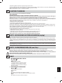
SICUREZZA AVVERTENZE
L’impianto elettrico è munito di collegamento a terra secondo le norme di sicurezza internazionali; è inoltre conforme alle normative
Europee sull’antidisturbo radio.
Non collegare l’apparecchio a condotti di scarico dei fumi prodotti dalla combustione (caldaie, caminetti,ecc). Verificare che la tensione
di rete corrisponda a quella riportata dalla targhetta posta all’interno della cappa.
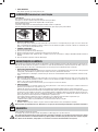
Non fare cotture a fiamma “libera” sotto la cappa. Controllare le friggitrici durante l’uso: I’olio surriscaldato potrebbe infiammarsi.
- Assicurarsi che vi sia una adeguata ventilazione nella stanza se la cappa è utilizzata con altri apparecchi che utilizzano combustibili
come gas o altro.
- Non accendere fiamme libere sotto la cappa.
- Non collegare l’apparecchio a condotti di scarico dei fumi prodotti dalla combustione (caldaie, caminetti, ecc).
- Assicurarsi che tutte le normative vigenti sullo scarico dell’aria all’esterno del locale siano rispettate prima dell’utilizzo della cappa.
Prima di procedere a qualsiasi operazione di pulizia o di manutenzione, disinserire l’apparecchio togliendo la spina o agendo sull’in-
terruttore generale. La casa costruttrice declina ogni responsabilità per eventuali danni che possano, direttamente o indirettamente,
essere causati a persone, cose ed animali domestici in conseguenza alla mancanza di tutte le prescrizioni indicate nell’apposito
libretto istruzioni e concernenti, specialmente, le avvertenze in tema di installazione, uso e manutenzione dell’apparecchio.
- Rischio di incendio se la pulizia non è condotta secondo le istruzioni del presente libretto.
ATTENZIONE: parti accessibili possono essere calde quando usate con apparecchi di cottura.
- La lunghezza massima della vite di fissaggio del camino (fornita dal fabbricante) è di 10 mm.
AVVERTENZA: l’installazione delle viti o dei dispositivi di fissaggio non conforme alle presenti istruzioni può comportare rischi di natura
elettrica.
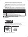
CARATTERISTICHE TECNICHE
B
I dati tecnici dell’elettrodomestico sono riportati su delle targhette, posizionate all’interno della cappa.
INSTALLAZIONE
C
(parte riservata solo a persone qualificate per il montaggio della cappa)
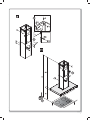
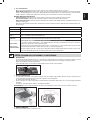
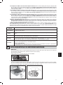
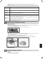
La distanza fra il piano cottura e la parte più bassa della cappa da cucina è di norma almeno 65 cm (vedi figura C1). Tale distanza è
misurata a rigore nel punto più basso della cappa con tensione non di sicurezza. Sulla base di questa dettaglio previsto dalle norme
Europee è possibile ridurre la distanza su alcuni modelli come specificato nel catalogo generale. Se le istruzioni del piano di cottura a
gas specificano una distanza maggiore, bisogna tenerne conto.
Nella versione aspirante il tubo di uscita dei fumi deve avere un diametro non inferire a quello del raccordo della cappa.
Nei tratti orizzontali il tubo deve avere una leggera inclinazione (10% circa) verso l’alto per convogliare l’aria all’esterno dell’ambiente.
Ridurre al minimo le curve, verificare che i tubi abbiano una lunghezza minima indispensabile.

9
Italiano
Rispettare le norme vigenti sullo scarico dell’aria all’esterno.
In caso di utilizzo contemporaneo di altre utenze (caldaie, stufe, caminetti, ecc.) alimentate a gas o con altri combustibili, provvedere ad
una adeguata ventilazione del locale in cui avviene l’aspirazione dei fumi, secondo le norme vigenti.
Istruzioni di montaggio: vedi sez. “O” del presente manuale.
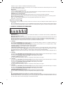
ALLACCIAMENTO ELETTRICO
D
(parte riservata solo a persone qualificate per l’allacciamento)
ATTENZIONE!
Prima di effettuare qualsiasi operazione all’interno della cappa scollegare l’apparecchio dalla rete elettrica.
Assicurarsi che non vengano scollegati o tagliati fili elettrici all’interno della cappa; nel caso si verifichino tali situazioni contattare
il centro assistenza più vicino. Per l’allacciamento elettrico rivolgersi a personale qualificato.
Il collegamento deve essere eseguito in conformità con le disposizioni di legge in vigore. Controllare che la valvola limitatrice e l’impianto
elettrico possano sopportare il carico dell’apparecchio (vedere targhetta caratteristiche tecniche al punto B). Alcuni tipi di apparecchi
possono essere dotati di cavo senza spina; in questo caso, la spina da utilizzare deve essere dei tipo “normalizzato” tenendo conto che:
- il filo giallo-verde deve essere utilizzato per la messa a terra,
- il filo blu deve essere utilizzato per il neutro,
- il filo marrone deve essere utilizzato per la fase, il cavo non deve entrare in contatto con parti calde aventi temperature superiori a
70°C.
- montare sul cavo di alimentazione una spina adatta al carico e collegarla ad una adeguata spina di sicurezza.
Se un apparecchio fisso non è provvisto di cavo di alimentazione e di spina, o di altro dispositivo che assicuri la disconnessione dalla
rete, con una distanza di apertura dei contatti che consenta la disconnessione completa nelle condizioni della categoria di sovratensione
III, le istruzioni devono indicare che tali dispositivi di disconnessione devono essere previsti nella rete di alimentazione conformemente
alle regole di installazione.
Il cavo di terra giallo/verde non deve essere interrotto dall’interruttore.
Prima di collegare l’apparecchio alla rete elettrica, controllare che:
- la tensione d’alimentazione corrisponda a quella indicata dalla targhetta caratteristiche tecniche.
- la presa di terra sia corretta e funzionale.
- l’impianto di alimentazione sia munito di efficace collegamento di terra secondo le norme vigenti.
- la presa o l’interruttore omnipolare usati siano facilmente raggiungibili con l’apparecchiatura installata.
La casa costruttrice declina ogni responsabilità nel caso le norme di sicurezza non vengano rispettate.
E
CAPPA IN VERSIONE
AD EVACUAZIONE ESTERNA (aspirante)
In questa versione i fumi e i vapori della cucina vengono convogliati verso l’esterno attraverso un tubo di scarico.
Il convogliatore di scarico che sporge sulla parte superiore della cappa deve essere collegato con un tubo che conduce i fumi e i vapori
in una uscita esterna.
In questa versione vanno tolti i filtri al carbone attivo se esistenti; per l’estrazione vedere istruzioni al punto F. Quando la cappa da cucina
viene utilizzata contemporaneamente ad altri apparecchi che impiegano gas o altri combustibili, il locale deve disporre di sufficiente
ventilazione secondo le norme vigenti.
Deviazione per la Germania:
Quando la cappa da cucina e apparecchi alimentati con energia diversa da quella elettrica sono in funzione simultaneamente, la pres-
sione negativa nel locale non deve superare i 4 Pa (4 x 10⁻⁵ bar).
F
CAPPA IN VERSIONE A RICICLO INTERNO (filtrante)
In questa versione l’aria passa attraverso i filtri di carbone attivo per essere purificata e viene riciclata nell’ambiente cucina.
Controllare che i filtri al carbone attivo siano montati sul motore, in caso negativo applicarli come indicato nelle istruzioni al punto H.
Se la cappa viene predisposta in versione filtrante rimuovere la valvola di non ritorno montata sul raccordo di uscita del motore.
Per il miglior rendimento si consiglia di utilizzare la terza velocità in presenza di forti odori e vapori, la seconda velocità nelle condi-
zioni normali, la prima velocità per mantenere l’aria pulita con bassi consumi di energia elettrica.
Si consiglia di mettere in funzione la cappa quando si inizia a cuocere e manteneria in funzione fino alla scomparsa degli odori.
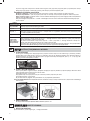
G
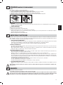
FUNZIONAMENTO
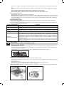
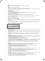
1. PULSANTIERA A 5 TASTI
LUCE - Pulsante
ON/OFF LUCE
MOTORE - Pulsante 1, 2, 3, OFF
1: avvia il motore alla velocità minima
2: avvia il motore alla velocità media
3: avvia il motore alla velocità massima
OFF: spegne il motore
2. PULSANTIERA ELETTRONICA
Pulsante luce
• ON: luce accesa (pulsante illuminato);
• OFF: luce spenta;

10
Pulsante -
Premendo il tasto si riduce la velocità del motore.
La velocità 1, 2 e 3 è visualizzata dal n° di led accesi escluso led luce e timer.
Pulsante +
Premendo il tasto si incrementa la velocità del motore.
La velocità 1,2 e 3 è visualizzata dal n° di led accesi escluso led luce e timer.
(Nella versione a 4 velocità il tasto + presenta una luce intermittente. La 4° velocità o intensiva è temporizzata e dopo circa 7 minuti
il motore passa automaticamente in 3° velocità).
Pulsante modalità
Funzione: accensione e spegnimento motore cappa.
La funzione velocità desiderata permette di avviare il motore con l’ultima velocità selezionata prima del precedente spegnimento.
Optional: versione con radiocomando (disponibile solo su alcune versioni).
AVVERTENZE (versione con radiocomando):
Posizionare l’apparecchio lontano da sorgenti di onde elettromagnetiche che potrebbero interferire con l’elettronica della cappa.
Distanza massima di funzionamento 5 metri. Tale distanza può variare in difetto in funzione delle interferenze elettromagnetiche di
altri apparecchi.
Pulsante luce del telecomando: on/off luce.
Pulsante – e + decremento/incremento velocità (per avviare il motore premere indifferentemente tasto + o in tasto -.
Pulsante timer: vedi istruzione sottostante.
Pulsante timer e saturazione filtri
- Questa funzione permette lo spegnimento automatico della cappa dopo 15 minuti di funzionamento alla velocità precedentemente
impostata (pulsante con luce intermittente).
- Dopo circa 30 ore di funzionamento il pulsante propone il lavaggio dei filtri metallici (pulsante illuminato di rosso). Per disattivare
l’allarme premere il pulsante timer per qualche secondo fino allo spegnimento della luce rossa. Successivamente spegnere la cappa
e riaccenderla per verificare l’annullamento dell’allarme.
3. PULSANTIERA ELETTRONICA CAPACITIVA
1: Timer/Allarme filtri
La luce fissa ROSSA sta ad indicare l’allarme filtro grassi attivato (dopo 30 ore), per disattivare questo allarme ed azzerare i contatori
tenere premuto il tasto per 3 secondi.
Luce ROSSA lampeggiante sta ad indicare che la funzione timer è attiva. Tale funzione è attivabile solo se alla pressione del tasto
(prolungata o meno) il motore è già attivo ad una velocità qualsiasi. Tale funzione determina l’autospegnimento della cappa dopo 15
minuti.
Con la funzione Timer attiva, la cappa può essere in ogni caso spenta dall’utente e la funzione verrà disattivata. La funzione Timer
rimane associata ad una velocità. Il cambio della velocità, con la funzione timer attiva, implica la disattivazione di quest’ultima.
2: 1° Velocità
Nella situazione di LED spento, la pressione non prolungata del tasto implica l’accensione della cappa al la 1° velocità e l’accensione
del relativo LED. La funzione si attiverà al rilascio del tasto.
Nella situazione di LED spento ed un’altra velocità attiva, la pressione del tasto implica la selezione della 1° velocità, l’accensione
del relativo LED e lo spegnimento del LED associato alla velocità precedentemente selezionata.
A LED accesso la pressione del tasto implica lo spegnimento del LED e del MOTORE.
A LED spento la pressione prolungata (almeno 3sec) del tasto implica l’attivazione della funzione ricircolo. Durante la funzione ricir-
colo (della durata 24 ore), il LED lampeggia. Dall’attivazione di tale funzione, la cappa resta accesa per 1 ora alla 1° velocità, poi si
ferma per 3 ore e si riattiva per un’altra ora. Tali cicli vengono ripetuti fino al timeout.
Con questa funzione attivata non si possono selezionare le altre velocità. Per Togliere questa funzione, tenere premuto per almeno
3 secondi il tasto 2.
3: 2° Velocità
Nella situazione di LED spento ed un’altra velocità attiva, la pressione del tasto (prolungata o meno) implica la selezione della 2°
velocità, l’accensione del relativo LED e lo spegnimento del LED associato alla velocità precedentemente selezionata.
Nella situazione di LED spento e nessuna velocità attiva, la pressione del tasto non ha effetto.
A LED accesso la pressione del tasto3 non ha effetti.
Per spegnere la cappa occorre selezionare prima la 1° velocità, poi premere nuovamente tale tasto.
4: 3° Velocità
Nella situazione di LED spento ed un’altra velocità attiva, l a pressione del tasto (prolungata o meno) implica la selezione della 3°
velocità, l’accensione del relativo LED e lo spegnimento del LED associato alla velocità precedentemente selezionata.
Nella situazione di LED spento e nessuna velocità attiva, la pressione del tasto non ha effetto.
A LED accesso la pressione del tasto4 non ha effetti.
Per spegnere la cappa occorre selezionare prima la 1° velocità, poi premere nuovamente tale tasto.
5: 4° Velocità
Nella situazione di LED spento ed un’altra velocità attiva, la pressione(prolungata o meno) del tasto implica la selezione della 4°
velocità, l’accensione del relativo LED e lo spegnimento del LED associato alla velocità precedentemente selezionata.
Nella situazione di LED spento e nessuna velocità attiva, la pressione del tasto non ha effetto.
A LED accesso la pressione del tasto5 non ha effetti.
La quarta velocità deve restare accesa per massimo 7 minuti, dopo di che si deve ritornare alla terza.
Per spegnere la cappa occorre selezionare prima la 1° velocità, poi premere nuovamente tale tasto.

11
Italiano
6: Luce - Remote Binding
Luce: La pressione breve del tasto T6 accende e spegne la luce. Il tasto T6 si illumina se la luce è accesa.
Remote Binding (opzionale): Con motore e luce spenta, la pressione lunga del tasto T6 attiva la modalità di associazione del teleco-
mando. Il Tasto T6 lampeggia per un massimo di 10 secondi. Durante il lampeggio deve essere premuto almeno un tasto del radioco-
mando. La funzione si disattiva allo scadere dei 10 secondi o prima se viene rilevato un telecomando compatibile.
Gestione della pressione dei tasti:
Pressione prolungata = dito presente sul tasto per almeno 3 secondi, la funzione si attiva durante la pressione.
Pressione non prolungata = dito presente sul tasto per meno di 3 secondi, la funzione di attiva al rilascio.
Radiocomando (opzionale): Posizionare l’apparecchio lontano da sorgenti di onde elettromagnetiche che potrebbero interferire con
l’elettronica della cappa.
Distanza massima di funzionamento 4 metri. Tale distanza può variare in difetto in funzione delle interferenze elettromagnetiche di
altri apparecchi.
Funz. Radiocom. DESCRIZIONE
Tasto Luce
La pressione del tasto Luce accende/spegne la luce
Tasto ‘ - ‘
La pressione del tasto ‘-’ decrementa la velocità del motore. Se si è in 1° velocità, la pressione del tasto ‘-’ spegne il motore
Tasto ‘ + ‘
Se il motore è spento, la pressione del tasto ‘+’ attiva il motore alla 1° velocità. Se il motore è in funzione, la pressione del
tasto ‘+’ incrementa la velocità fino alla massima.
Tasto Timer
Se il motore è attivo, la pressione del tasto timer attiva/disattiva la funzione timer
Cambio Codice
(solo in caso di
malfunzionamento)
Premere il tasto “Luce” insieme al tasto “Timer” del radiocomando fino a che il led blu non inizia a lampeggiare lentamen-
te. Se entro 5 secondi si preme il tasto “-” del radiocomando viene generato e memorizzato il nuovo codice. La memoriz-
zazione viene confermata da 3 lampeggi brevi del led.
Per ritornare al codice di default bisogna premere il tasto “-” insieme al tasto “+” del radiocomando per più di 5 secondi.
La memorizzazione del codice di default viene segnalata con 3 brevi lampeggi del led.
Ogni volta che viene generato un nuovo codice o impostato il codice di default nel telecomando, bisogna eseguire anche
la procedura Remote Binding (Tasto Luce della pulsantiera) descritta precedentemente.
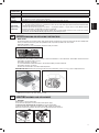
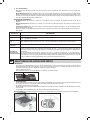
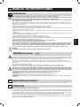
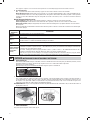
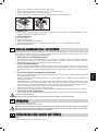
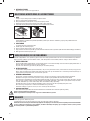
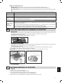
FILTRI ISTRUZIONI PER L’ESTRAZIONE E LA SOSTITUZIONE
H
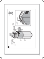
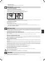
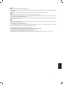
1. FILTRI METALLICI
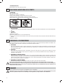
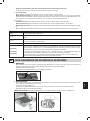
Per l’estrazione dei filtro metallico antigrasso è sufficiente agire sulla maniglia A fino a quando esce dalla guida anteriore; a questo
punto, inclinando leggermente verso il basso, farlo uscire dalla guida posteriore. Per l’inserimento invertire l’operazione.
Cappe con pannello per aspirazione perimetrale:
- aprire il pannello (vedi fig. 1). Per rimuovere il filtro metallico antigrasso agire sulla maniglia A.
A
2. FILTRI AL CARBONE ATTIVO
Per la sostituzione dei filtri al carbone attivo si proceda come segue: togliere i filtri metallici come indicato sopra. A questo punto si
accede facilmente ai due filtri che sono agganciati sul lato dx e sx del convogliatore.
Per il montaggio/sostituzione vedi figura.
Nel caso di cappa con camera motore il filtro è posizionato nella parte inferiore della camera stessa. Per il montaggio/sostituzione
vedi figura.
Per ordinare i nuovi filtri carbone rivolgersi al distributore/rivenditore.
SOLO PER ITALIA: Scaricare l’apposito modulo ordine filtro sul sito: www.falmec.com (accedere sul menù a tendina assistenza).
3. PANNELLO REMOVIBILE
Per rimuovere il pannello seguire l’istruzione in fig. H3

12
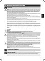
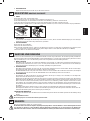
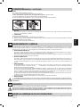
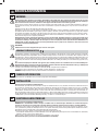
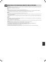
ILLUMINAZIONE MONTAGGIO E SOSTITUZIONE
I
1. FARETTO
Per sostituire la lampada del “Square halogen light”:
a) Accertarsi che l’apparecchio sia scollegato dalla rete elettrica.
b) Aprire completamente il pannello fino ad un angolo di 90° (vedi figura) premendo su PUSH
c) Sostituire la lampada con una analoga (alogena max 20 W, 12 Volt attacco G4).
d) Richiudere i pannello. Se il pannello non si richiude correttamente ripetere l’operazione al punto b.
Square halogen light
2. FARETTO LED
In questo caso la cappa è dotata di illuminazione di faretti led ad alta efficienza, basso consumo e durata molto elevata in condizioni
di normale utilizzo.
3. LAMPADA FLUORESCENTE
Sostituzione del tubo fluorescente:
a) Scollegare l’apparecchio dalla rete di alimentazione;
b) Rimuovere l’eventuale pannello in acciaio svitando le viti di fissaggio;
c) Togliere il tubo fluorescente ruotandolo di 90° e sostituirlo con uno di analoghe caratteristiche (8W-13W-21W-28W a seconda del
modello);
d) Ricollegare l’apparecchio alla rete di alimentazione.
MANUTENZIONE E PULIZIA
L
Una costante manutenzione garantisce un buon funzionamento ed un buon rendimento nel tempo. Particolari attenzioni vanno rivolte ai
filtri metallici antigrasso ed ai filtri al carbone attivo, infatti la pulizia frequente dei filtri e dei loro supporti garantisce che sulla cappa non
si accumulino grassi che sono pericolosi per la facilità di incendio.
1. FILTRI ANTIGRASSO METALLICI
Hanno la funzione di trattenere le particelle grasse in sospensione, pertanto si consiglia di lavarli ogni mese in acqua calda e deter-
sivo evitando di piegarli. Attendere che siano ben asciutti prima di rimontarli.
Per lo smontaggio e montaggio vedi istruzioni al punto H1. Si raccomanda costante frequenza nell’operazione.
2. FILTRI AL CARBONE ATTIVO
Hanno la funzione di trattenere gli odori presenti nel flusso d’aria che li attraversa. L’aria depurata per successivi passaggi attraverso
i filtri viene rimessa nell’ambiente cucina. l filtri al carbone attivo non possono essere lavati e vanno sostituiti mediamente ogni 3-4
mesi (dipende poi dall’uso). Per la sostituzione dei filtri al carbone attivo seguire le istruzioni come al punto H2.
3. PULIZIA ESTERNA
Si raccomanda di pulire le superfici esterne delle cappe almeno ogni 15 giorni per evitare che le sostanze oleose o grasse possano
intaccare le superfici in acciaio.
La pulizia della cappa va eseguita usando un panno umido con detersivo liquido neutro o con alcool denaturato.
Nel caso di materiale con trattamento antimpronta (Fasteel) eseguire la pulizia solo con acqua e sapone neutro utilizzando un panno
morbido avendo cura di risciacquare e asciugare accuratamente. Non si devono utilizzare prodotti contenenti sostanza abrasive,
panni con superfici ruvide o panni comunemente in commercio per la pulizia dell’acciaio. L’utilizzo di sostanze abrasive e panni ruvidi
danneggerà irreparabilmente il trattamento superficiale dell’acciaio.
Conseguenza diretta del non rispetto di tali avvertenze sarà il deterioramento irreversibile della superficie dell’acciaio.
Tali avvertenze dovranno essere conservate insieme al libretto istruzioni della cappa.
Il produttore declina ogni responsabilità qualora non vengano rispettate tali istruzioni.
4. PULIZIA INTERNA
É vietata la pulizia di parti elettriche o parti relative al moto re all’interno della cappa, con liquidi o solventi;
Non usare prodotti contenenti abrasivi.
Effettuare tutte queste operazioni scollegando preven tivamente l’apparecchio dalla rete elettrica.
GARANZIA
M
La sua nuova apparecchiatura è coperta da garanzia.
Le condizioni di garanzia sono riportate per esteso sull’ulti ma pagina di copertina di questo libretto.
La casa costruttrice non risponde delle possibili ine sattezze, imputabili ad errori di stampa o di trascrizio ne, contenute nel presente
libretto. Si riserva di appor tare ai propri prodotti quelle modifiche che ritenesse necessarie o utili, anche nell’interesse dell’utenza,
senza pregiudicare le caratteristiche essenziali di fun zionalità e di sicurezza.
N
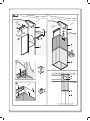
MONTAGGIO CAPPA AD ISOLA CON TRALICCIO
AVVERTENZA: L’installazione di viti o dispositivi di fissaggio non in conformità con le presenti istruzioni può comportare pericolo di
folgorazione.

13
Italiano
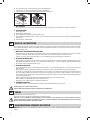
Fase 1
- Individuare l’altezza desiderata per il posizionamento della cappa (Fig. C1).
- Far scorrere i tralicci (C) e (C1) fino ad ottenere l’altezza desiderata (H1), successivamente bloccarli con 8 viti (V2) autofilettanti (Fig.A).
- Fissare il traliccio (C) al soffitto utilizzando 4 fischer da Ø 8 e relative viti (V1) (Fig. 2 + 2 bis).
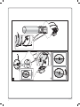
Fase 2
- Infilare la prolunga sul camino e bloccarli tra loro con dello scotch di carta (Fig. 2).
- Fissare l’assieme camino-prolunga (D+E) al traliccio (C) tramite le 4 viti metriche M4 (V3) inserite nei fori già esistenti senza bloccarle
definitivamente (Fig. 2).
- Nel caso di versione aspirante: individuare l’altezza ottimale del tubo rigido o flessibile di scarico dei fumi (F) e collegarlo al raccordo
motore (N) (Fig. 1-2-2 bis)).
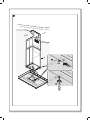
Fase 3
- Alzare la cappa agganciandola alle 4 viti metriche M5 (V4) pre-avvitate al traliccio (C) (centrare i fori Ø11 sull’asola dell’intercamera e
traslarla lateralmente) (Fig. 3).
- Serrare definitivamente le 4 viti M5 (V4) (Fig. 3).
- Togliere lo scotch di carta (Fig. 4), togliere le 4 viti metriche M4 (V3) avvitate precedentemente sul traliccio e far scorrere verso il basso
l’assieme camino-prolunga.
- Eseguire il collegamento del tubo al raccordo del foro di scarico del soffitto (nel caso di versione aspirante).
- Eseguire il collegamento elettrico solo dopo aver disinserito l’alimentazione elettrica.
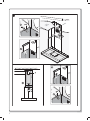
- Fissare la prolunga al traliccio (C) tramite le 4 viti metriche M4 (V3), senza bloccarle definitivamente.
- Bloccare definitivamente la prolunga sul traliccio (C) serrando le 4 viti metriche M4 (V3).
- Bloccare il camino tramite viti autofilettanti (V5) (Fig. 5).
- Utilizzare gli elementi supporto prolunga (A) (Fig. 2 bis) solo nel caso non venga usato il traliccio superiore, oppure nel caso di un
contro-soffitto.

14
GB
INSTRUCTIONS BOOKLET
WARNINGS
A
This instruction booklet must be kept together with the appliance for future reference. If the appliance is sold or consigned to other
parties, check that the booklet is supplied with it, to ensure that the new user has the correct information on the operation of the range
hood and is aware of the warnings. These warnings have been provided for the your safety and the safety of others. As a result, please
read them carefully before installing and operating the appliance.
This appliance is not intended for use by persons (including children) with reduced physical, sensory or mental capabilities, or lack of
experience and knowledge, unless they have been given supervision or instruction concerning use of the appliance by a person respon-
sible for their safety.
Children should be supervised to ensure that they do not play with the appliance.
The appliance must be installed by qualified personnel, in accordance with the standards in force. If the supply cord is damaged, it must
be re-placed by the manufacturer, its service agent or similarly qualified persons in order to avoid a hazard. Any modifications that may
be required to the electrical system for the installation of the range hood must only be made by qualified electricians. It is dangerous to
modify or attempt to modify the characteristics of this system. In the event of malfunctions or if repairs are required to the appliance, do
not attempt to solve the problems directly.
Repairs performed by unqualified persons may cause damage. For all repair and other work on the appliance, contact an authorised
service/spare parts centre.
Always check that all the electrical parts (lights, exhaust device), are off when the appliance is not being used. Read the entire instruction
booklet before performing any operations on the range hood.
The range hood must only be used for the exhaust of cooking fumes in home kitchens. The manufacturer disclaims all liability for any
other use of the appliance.
The maximum weight of any object placed above the hood, or hung to it (if possible) must not exceed 1,5 kilos. After installing the
stainless steel hood, clean it in order to remove any residue of the protective glue, and stains of grease or oil. The manufacturer
recommends its cleaning cloth available for purchase. The manufacturer accepts no liability in case of damage caused by the use of
different detergent types.
CAUTION:
This product must be disposed of at end of life according to the rules in force.
SAFETY WARNINGS
The electrical system features an earth connection in compliance with international safety standards; furthermore, it is compliant with
the European standard for electromagnetic compatibility.
Do not connect the appliance to flues (from boilers, fireplaces, etc.). Make sure the mains voltage corresponds to the values on the rating
plate located inside the range hood.
Never cook on “open” flames under the range hood.
Check deep-fryers during use: superheated oil may be flammable.
- Ensure there is adequate ventilation of the room when the rangehood is used at the same time as appliances burning gas or other fuels.
- Do not flambe under the rangehood
- The exhaust air must not be discharged into a flue which is used for exhausting fumes from appliances burning gas or other fuels.
- Ensure that all regulations concerning the discharge of exhaust air have been fulfilled before you use the appliance.
Before performing any cleaning or maintenance operations, disconnect the appliance by unplugging it or using the main switch. The
manufacturer disclaims all liability for any damage that may be directly or indirectly caused to people, things and animals due to the
failure to follow all the instructions provided in this booklet and above all the warnings relating to the installation, operation and
maintenance of the appliance.
- there is a fire risk if cleaning is not carried out in accordance with the instructions.
CAUTION: Accessible parts may become hot when used with cooking appliances.
- Max. length screw for fixing the chimney is 10 mm (provided by the manufacturer).
WARNING: Failure to install the screws or fixing device in accordance with these instructions may result in electrical hazards.
Warning only for Australia: hood width less than 90 cm: use max. 4 hobs
TECHNICAL SPECIFICATIONS
B
The technical data pertaining to the electric appliance The technical specifications of the appliance are shown on the rating plates
located inside the range hood.
INSTALLATION
C
(Section reserved for qualified installers of the range hood)
The distance between the hob and the lowest part of the rangehood is normally at least 65 cm (see figure C1). This distance is measuresd
in the lowest part of the rangehood not operating at safety voltage. Based on this detail provided by European Standards, the distance
may be reduced in some models as specified in the general catalogue. If the instructions for installation for the gas hob specify a greater
distance, this has to be taken into account.
In the outside exhaust version, the diameter of the fume discharge duct must be no smaller than the range hood connection.
In the horizontal sections, the duct must slope slightly (around 10%) upwards, so as to better convey the air outside of the room.
Avoid using angled pipes, make sure that the pipes are at least of the minimum length.
Comply with the current regulations on air discharge into the atmosphere.

15
English
If a boiler, stove, fireplace, etc. that uses gas or other fuels is being used at the same time, make sure the room where the fumes are
extracted is well ventilated, in compliance with the current regulations.
Mounting instruction: see section “O” of the booklet.
ELECTRICAL CONNECTIONS
D
(Section reserved for qualified installers)
WARNING!
Before doing any work inside the range hood, disconnect the appliance from the mains power supply.
Check that the wires inside the range hood are not disconnected or cut; if this is the case, contact your nearest service centre. The
electrical connections must be performed by qualified personnel.
The connections must be performed in compliance with the legal standards in force. Check that the relief valve and the electrical system
are able to support the load of the appliance (see the technical specifications in point B).
Some types of appliance are supplied with a cable without plug; in this case, “standardised” plugs must be used, keeping in mind that:
- the yellow-green wire must be used for the earth,
- the blue wire must be used for the neutral,
- the brown wire must be used for the phase; the cable must not come into contact with hot parts (over 70°C).
- fit a plug that is suitable for the load to the power cable, and connect it to a suitable power outlet.
For appliances that come supplied with cable and plug please ensure they are plugged into a circuit suitable for this appliance.
Please refer to a qualifed person. (See technical specifications in point B).
The manufacturer declines all liability if the safety standards are not observed.
E
RANGE HOOD WITH OUTSIDE DISCHARGE (exhaust)
In this version, the fumes and steam from the kitchen are conveyed outside through an exhaust duct.
The exhaust conveyor that protrudes from the upper part of the range hood must be connected to a duct that carries the fumes and steam
outside. In this version, the charcoal filters, if fitted, should be removed; to do this, see the instructions in point F. There must be adequate
ventilation of the room when the range hood is used at the same time as appliances burning gas or other fuels, according to the standard.
Deviation for Germany:
When the range hood and appliances supplied with energy other than electricity are simultaneously in operation, the negative pressure
in the room must not exceed 4 Pa (4x10 E-5 bar).
F
RECIRCULATING RANGE HOOD (with filter)
In this version, the air passes through charcoal filters for purification, and is then recirculated back into the kitchen.
Check that the charcoal filters are fitted to the motor, and if not, install them as described in the instructions in point H.
If the hood is of filtering type, remove the non-return valve fitted at the motor’s outlet.
For maximum efficiency, the third speed should be used when there are strong odours or a lot of steam, the second speed in normal
conditions, and the first speed for keeping the air clean with minimum energy consumption. The range hood should be switched on
when starting to cook, and left on until the odours disappear.
G
OPERATION
1. FIVE BUTTON CONTROL PANEL
LIGHT- button
Pressed: the light is on
Released: the light is off
MOTOR button - 1, 2, 3, OFF
1: starts the motor at minimum speed
2: starts the motor at medium speed
3: starts the motor at maximum speed
OFF: stops the motor
2. ELECTRONIC CONTROL PANEL
Light pushbutton
- ON: light on (the pushbutton is lit);
- OFF: light off;
Pushbutton -
Press to reduce motor speed
Speed 1, 2 and 3 are indicated by the number of LEDs that light up (excluding the light and the timer LEDs).
Pushbutton +
Press to increase motor speed
Speed 1, 2 and 3 are indicated by the number of LEDs that light up (excluding the light and the timer LEDs).
(In the 4-speed version the pushbutton + blinks. The fourth speed remains on for a set duration of time. After 7 minutes the motor
returns to the third speed).
Mode pushbutton
Function: it turns hood motor on and off.
The function “desired speed” enables to start the motor at the speed that was selected before the hood was last turned off.
Optional: version with remote control (some versions only).
WARNING:

16
Install the hood away from sources of electromagnetic waves, as these could affect the correct operation of the electronic system.
Maximum operating distance: 5 metres. The maximum operating distance could be less than 5 metres in case of electromagnetic
interference by other equipment.
Light pushbutton on remote control: light on/off.
– and + pushbutton: increase/decrease speed (to start the motor press either the + or the – pushbutton).
Timer pushbutton: see instructions below.
Timer and ‘filter clogged’ alarm pushbutton
- This function allows the automatic turning off of the hood after running for 15 minutes at the speed previously set (the pushbutton
shows a flickering light).
- After about 30 hours of running the pushbutton indicates the need for washing the metal filters (the pushbutton shows a solid red
light). To disable the alarm press the pushbutton for a few seconds until the red light turns off. Then turn the hood off and on again
to check that the alarm has disappeared.
3. ELECTRONIC CONTROL PANEL
1: Timer/Alarm filters
The steady RED light indicates that the fat filter alarm is activated (after 30 hours), to deactivate this alarm and zero the meters,
maintain the Key pressed for 3 seconds.
Flashing RED light indicates that the timer function is activated. This function can only be activated if the motor is activated and run-
ning at any velocity when the Key is pressed (either prolonged or not). This function will cause the automatic switch-off of the hood
after 15 minutes.
With the Timer function activated, the hood can be switched-off by the operator in any case and the function will be deactivated.
The Timer function remains associated to a velocity. A change in the velocity, with the Timer function activated, will deactivate it.
2: 1st Velocity
When the LED is switched-off, non-prolonged pressing of the key will switch-on the hood at the 1
st
velocity and illuminate the re-
spective LED. The function will switch-on when the Key is released.
When the LED is switched-off and another velocity is activated, pressing the Key will imply selection of the 1
st
velocity, switching-on
of the respective LED and switching-off of the LED associated with the velocity that was previously selected.
When the LED is on, pressing the Key will imply the switching-off the LED and MOTOR.
When the LED is switched-off, prolonged pressing (at least 3 seconds) of the Key will cause activation of the recirculation function.
During the recirculation function (with a duration of 24 hours), the LED will flash. From the activation of this function, the hood will
remain switched-on for one hour at the 1
st
velocity, after which it will switch-off for 3 hours and then reactivate for another hour.
These cycles are repeated until the timeout.
With this function activated, the other functions cannot be selected. To remove this function, keep Key 2 pressed for at least 3 sec-
onds.
3: 2nd Velocity
When the LED is switched-off and another velocity activated, pressing the Key (either prolonged or not) will imply the selection of
the 2
nd
velocity, switching-on of the respective LED and switching-off of the LED associated with the velocity that was previously
selected.
When the LED is switched-off and no velocity activated, pressing the Key will have no effect.
When the LED is switched-on, pressing the Key 3 will have no effect.
To switch the hood off, it will be necessary to firstly select the 1
st
velocity and then repress the same Key.
4: 3rd Velocity
When the LED is switched-off and another velocity activated, pressing the Key (either prolonged or not) implies the selection of
the 3
rd
velocity, the switching-on of the respective LED and switching-off of the LED associated to the velocity that was previously
selected.
When the LED is switched-off and no velocity activated, pressing the Key will have no effect.
When the LED is switched-on, pressing the Key 4 will have no effect.
To switch the hood off, it will be necessary to firstly select the 1
st
velocity and then repress the same Key.
5: 4th Velocity
When the LED is switched-off and another velocity activated, pressing the Key (either prolonged or not) implies the selection of the
4
th
velocity, switching-on of the respective LED and switching-off of the LED associated to the velocity that was previously selected.
When the LED is switched-off and no velocity activated, pressing the Key will have no effect.
When the LED is switched-on, pressing the key 5 will have no effect.
The forth velocity must remain on for a maximum of 7 minutes, after which, one must return to the third.
To switch the hood off, it will be necessary to firstly select the 1
st
velocity and then repress the same key.
6: Light - Remote Binding
Light: Briefly pressing key T6 will turn the light on and off. The T6 key will light up if the light is on.
Remote Binding (optional): With motor and light turned off, applying prolonged pressure on the T6 key will activate remote binding
mode. The T6 Key will flash for a maximum of 10 seconds. During flashing, at least one radio control key must be pressed. The func-
tion will deactivate upon completion of the 10 seconds, or earlier if a compatible remote control is detected.
Key pressure management:
Prolonged pressure = finger pressed on key for at least 3 seconds, the function activates during pressure.
Non-prolonged pressure = finger pressed on key for less than 3 seconds, the function activates upon its release.
Radio control (optional): Place the device far from sources of electromagnetic waves which could interfere with the range hood’s
electronic functions
Maximum operating distance 4 metres. This distance may vary in defect based on electromagnetic interference of other devices.

17
English
Function of the
remote control
DESCRIPTION
Light Key
Pressing the Light key will switch the light on/off
‘ - ‘ Key
Pressing the ‘-’ Key will decrease motor speed. If 1° (1st) speed is in gear, pressing the ‘-’ key will turn off the motor
‘ + ‘ Key
If the motor is turned off, pressing the ‘+’ key will activate the motor at 1° (1st) speed. If the motor is operating, pressing the
‘+’ key will increase motor speed up to the maximum.
Timer Key
If the motor is active, pressing the timer key will activate/deactivate the timer function
Code Change
(only in case of
malfunction)
Press the “Luce” (Light) key together with the “Timer” key of the remote control until the blue LED begins to slowly flash. If
the “-” key of the remote control is pressed within 5 seconds, the new code will be generated and memorised. Memorisation
is confirmed by 3 brief flashes of the LED.
To return to the default code, apply pressure on the “-” key together with the “+” key for over 5 seconds. Memorisation of
the default code will be signalled with 3 brief flashes of the LED.
Each time that a new code is generated or that the default code is set in the remote control, it is necessary to also carry out
the previously described Remote Binding (Light Key of the pushbutton) procedure.
FILTERS REMOVING AND REPLACING’S INSTRUCTIONS
H
1. METAL FILTERS
To remove the metal grease-trapping filter, simply pull the handle A until releasing it from the front guide; then tilt it slightly down-
wards, and slide it out of the rear guide. To reposition the filter, repeat the operation in the reverse order.
Hoods with perimeter suction:
- Open the panel (see fig. 1). Use handle A to remove the metal grease filter.
A
2. CHARCOAL FILTERS
To replace the charcoal filters, proceed as follows: remove the metal filters as described above. The two filters located at the ends
of the motor can now be easily accessed.
To install the new fi lters see picture.
In case of hood with the motor box the fi lter is located on the botton part of the motor box.
To install the new fi lters see picture.
To order new charcoal fi lters contact the distributor/retailer.
VALID ONLY FOR ITALY: download the appropriate order form from: www.falmec.com (access the assistance drop-down menu).
3. REMOVABLE PANEL
Follow the instructions on fig. H3 to remove the panel.
LIGHTING ASSEMBLY AND REPLACEMENT
I
1. SPOTLIGHT
How to replace a square halogen light:
a) Check that the equipment is disconnected from the power supply.
b) Open the panel completely till 90° (see figure) pressing the PUSH button
c) Replace the lamp with a similar one (halogen, max 20 W, 12 Volt, G4 connection).
d) Close the panel. If the panel does not close correctly repeat the operation at point b.
Square halogen light

18
2. LED SPOTLIGHT
In this case the hood is equipped with high efficiency, low power LED spotlights with extremely high durability under normal use
conditions.
3. FLUORESCENT TUBE
Replacing the fluorescent tube:
a) Disconnect the device from the mains;
b) Unscrew the fixing screws and remove the bottom panel;
c) Remove the fluorescent tube, by rotating through 90°, and replace it with one of similar features (8W-13W-21W-28W according with
the model);
d) Reconnect the device to the mains.
MAINTENANCE AND CLEANING
L
Constant maintenance ensures the correct operation and efficiency of the appliance over time. Special attention should be paid to the
metal grease-trapping filters and the charcoal filters. Frequent cleaning of the filters and their supports will ensure that fats and grease
do not accumulate on the range hood, with the consequent risk of fire.
1. METAL GREASE-TRAPPING FILTERS
These trap the fat and grease particles suspended in the air, and therefore should be washed every month in hot water and deter-
gent, without bending them. Wait until they are completely dry before repositioning them. To remove and replace these
filters, see the instructions in point H1. This operation should be performed at regular intervals.
2. CHARCOAL FILTERS
These trap the odours present in the stream of air that passes through them. The air is purified by passing a number of times through
the filters and being recirculated into the kitchen. The charcoal filters cannot be cleaned, and should be replaced on average every
3-4 months (according to use). To replace the charcoal filters, see the instructions in point H2.
3. CLEANING THE OUTSIDE OF THE APPLIANCE
It is advised to clean the external hood surfaces at least every 15 days in order to avoid that oily or greasy substances affect the steel
surfaces.
The ouside of the range hhod should be cleaned using a damp cloth and neutral liquid detergent or denatured alcohol.
In case of fingerprint-less finish (fasteel) clean only with water and neutral soap using clean with a soft cloth, rinse and wipe dry
thoroughly. Do not use products that contain abrasive substances, rough cloths or cloths specifically designed for cleaning steel. Us-
ing abrasive substances or rough cloths will inevitably damage the finish of steel. The steel surface will be irrevocably damaged if the
instructions above are not complied with.
Keep these instructions together with the instructions for use of your hood.
The manufacturer accepts no liability for any damage caused by non-compliance with the instructions above.
4. CLEANING THE INSIDE OF THE APPLIANCE
The electrical parts or parts of the motor assembly inside the range hood must not be cleaned using liquids or solvents.
Do not use abrasive products. All the above operations must be performed after having disconnected the appliance from the mains
power supply.
WARRANTY
M
The new equipment is covered by warranty.
The warranty conditions are provided by the distributor.
The manufacturer is not liable for any inaccuracies in this booklet resulting from printing or transcription errors. The manufacturer
reserves the right to modify its products as it considers necessary or in the interests of the user, without compromising their essential
safety and operating characteristics.
N
INSTALLATION OF ISLAND HOOD WITH LATTICE-WORK
WARNING: Failure to install the screws or fixing device in accordance with these instructions may result in electrical hazards.
Step 1
- Identify the desired height for the positioning of the hood (Fig. C1).
- Slide the lattice-works (C) and (C1) to the desired height (H1), then block them with the 8 self-threading screws (V2) (Fig.A).
- Fasten the lattice-work (C) to the ceiling using the four Ø 8 expansion plugs and relative screws(V1) (Fig. 2 + 2 bis).
Step 2
- Insert the extension on the flue and fasten them to each other with masking tape (Fig. 2).
- Fasten the flue-extension assembly (D+E) to the lattice-work (C) with the 4 M4 metric screws (V3) inserted in the existing holes without
tightening them completely (Fig. 2).
- For suction version: identify the optimal height for the rigid or flexible exhaust pipe (F) and connect it to the motor connection (N) (Fig.
1-2-2 bis).
Step 3
- Raise the hood, hooking it onto the 4 M5 metric screws (V4) pre-tightened to the lattice-work (C) (center the Ø11 holes on the slot of the
inner liner and move it laterally)(Fig. 3).
- Completely tighten the 4 M5 screws (V4) (Fig. 3).
- Remove the masking tape (Fig. 4), remove the four M4 metric screws (V3) previously tightened onto the lattice-work and slide the flue-
extension assembly downwards.
- Connect the pipe to the connection of the ceiling discharge hole.
- Make electrical connections only after having removed electrical power supply.
- Fasten the extension to the lattice-work (C) by means of the 4 M4 metric screws(V3), without tightening them completely.
- Block the extension completely to the lattice-work (C) by screwing down the 4 M4 metric screws (V3).
- Block the flue with the self-threading screws (V5) (Fig. 5).
- Use the extension support elements(A) (Fig. 2 bis) only if the upper lattice-work is not used, or in the case of a false ceiling.
La pagina sta caricando ...
La pagina sta caricando ...
La pagina sta caricando ...
La pagina sta caricando ...
La pagina sta caricando ...
La pagina sta caricando ...
La pagina sta caricando ...
La pagina sta caricando ...
La pagina sta caricando ...
La pagina sta caricando ...
La pagina sta caricando ...
La pagina sta caricando ...
La pagina sta caricando ...
La pagina sta caricando ...
La pagina sta caricando ...
La pagina sta caricando ...
La pagina sta caricando ...
La pagina sta caricando ...
La pagina sta caricando ...
La pagina sta caricando ...
La pagina sta caricando ...
La pagina sta caricando ...
La pagina sta caricando ...
La pagina sta caricando ...
La pagina sta caricando ...
La pagina sta caricando ...
La pagina sta caricando ...
La pagina sta caricando ...
La pagina sta caricando ...
La pagina sta caricando ...
La pagina sta caricando ...
La pagina sta caricando ...
La pagina sta caricando ...
La pagina sta caricando ...
La pagina sta caricando ...
La pagina sta caricando ...
La pagina sta caricando ...
La pagina sta caricando ...
La pagina sta caricando ...
La pagina sta caricando ...
La pagina sta caricando ...
La pagina sta caricando ...
La pagina sta caricando ...
La pagina sta caricando ...
La pagina sta caricando ...
La pagina sta caricando ...
La pagina sta caricando ...
La pagina sta caricando ...
La pagina sta caricando ...
La pagina sta caricando ...
La pagina sta caricando ...
La pagina sta caricando ...
La pagina sta caricando ...
La pagina sta caricando ...
La pagina sta caricando ...
La pagina sta caricando ...
La pagina sta caricando ...
La pagina sta caricando ...
La pagina sta caricando ...
La pagina sta caricando ...
La pagina sta caricando ...
La pagina sta caricando ...
La pagina sta caricando ...
La pagina sta caricando ...
-
 1
1
-
 2
2
-
 3
3
-
 4
4
-
 5
5
-
 6
6
-
 7
7
-
 8
8
-
 9
9
-
 10
10
-
 11
11
-
 12
12
-
 13
13
-
 14
14
-
 15
15
-
 16
16
-
 17
17
-
 18
18
-
 19
19
-
 20
20
-
 21
21
-
 22
22
-
 23
23
-
 24
24
-
 25
25
-
 26
26
-
 27
27
-
 28
28
-
 29
29
-
 30
30
-
 31
31
-
 32
32
-
 33
33
-
 34
34
-
 35
35
-
 36
36
-
 37
37
-
 38
38
-
 39
39
-
 40
40
-
 41
41
-
 42
42
-
 43
43
-
 44
44
-
 45
45
-
 46
46
-
 47
47
-
 48
48
-
 49
49
-
 50
50
-
 51
51
-
 52
52
-
 53
53
-
 54
54
-
 55
55
-
 56
56
-
 57
57
-
 58
58
-
 59
59
-
 60
60
-
 61
61
-
 62
62
-
 63
63
-
 64
64
-
 65
65
-
 66
66
-
 67
67
-
 68
68
-
 69
69
-
 70
70
-
 71
71
-
 72
72
-
 73
73
-
 74
74
-
 75
75
-
 76
76
-
 77
77
-
 78
78
-
 79
79
-
 80
80
-
 81
81
-
 82
82
-
 83
83
-
 84
84


Falmec Astra Island Manuale del proprietario
- Categoria
- Cappe da cucina
- Tipo
- Manuale del proprietario
- Questo manuale è adatto anche per
in altre lingue
- English: Falmec Astra Island Owner's manual
- français: Falmec Astra Island Le manuel du propriétaire
- español: Falmec Astra Island El manual del propietario
- Deutsch: Falmec Astra Island Bedienungsanleitung
- русский: Falmec Astra Island Инструкция по применению
- português: Falmec Astra Island Manual do proprietário
- dansk: Falmec Astra Island Brugervejledning
- polski: Falmec Astra Island Instrukcja obsługi
- svenska: Falmec Astra Island Bruksanvisning
- suomi: Falmec Astra Island Omistajan opas

