Yamaha EM-202VCD Manuale utente
- Categoria
- Ricevitore
- Tipo
- Manuale utente

VIDEO CD CHANGER RECEIVER EM
–
202VCD
PHONES
POWER
DISC
123
PROGRAM
ECHO ECHO
MUSIC
USER
MEMORY
INPUT SELECTOR
VCR/LD-TV/VCD-CD/TUNER/TAPE•MD/AUX
VOLUME
RANDOM
DISPLAY
MIC
MIN MAX
MIC MIXING
REPEAT TIME MEMORY AUTO/MAN'L
HOUR
PRESET/TUNING/BAND
A/B/C/D/E
MIN TIME ADJ TIMER
OPEN/
CLOSE
DISC
CHANGE
VIDEO CD
Version 2.0
/
Playback Control
VIDEO CD CHANGER RECEIVERVIDEO CD CHANGER RECEIVER
OWNER’S MANUALOWNER’S MANUAL
T

22
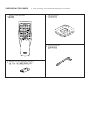
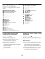
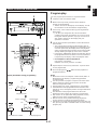
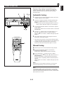
SUPPLIED ACCESSORIES
●
After unpacking, check that the following parts are contained.
●
Remote control transmitter
●
●
Batteries (size AA, UM/SUM-3, R6, HP-7)
●
●
AM loop antenna
●
●
Indoor FM antenna
●
TIME
A
PROG
B C D
+I0
E
VCD/CD
1
1
2
2
3
3
4
4
5
5
6
6
7
7
8
8
9 0
PRESET
INPUT
TIME INDEX
INTRO DIGEST
POWER
DISPLAY
SLEEP
MUSIC
FLAT
PROGRAM
USER
VOLUME
DISC SKIP
RETURN
PREV NEXT
SELECT
LEVEL
TEST
CENTER/REAR
/DELAY
ECHO/
KEY
OPEN/CLOSE
INDEXMODE
TUNER

33
PHONES
POWER
DISC
123
PROGRAM
ECHO ECHO
MUSIC
USER
MEMORY
INPUT SELECTOR
VCR/LD-TV/VCD-CD/TUNER/TAPE•MD/AUX
VOLUME
RANDOM
DISPLAY
MIC
MIN MAX
MIC MIXING
REPEAT TIME MEMORY AUTO/MAN'L
HOUR
PRESET/TUNING/BAND
A/B/C/D/E
MIN TIME ADJ TIMER
OPEN/
CLOSE
DISC
CHANGE
VIDEO CD
Version 2.0
/
Playback Control
MHz
PRESET
USER
NOR TEST
PHANTOM
TIMER
SLEEP
STEREO
TUNED MEMORY
AUTO
PROGRAMMUSIC
ROCK BLUES
RAP JAZZ
PRO LOGIC HALL ARENA
3 STEREO KARAOKE L R
1 2
3 4
100 350 1K 3.5K 10K
VOLUME
G
8 976543
HI F EJ
1
2
D
0
B
A
C
1 2 3 4 5 6 7 8 9 0 A
B
C ED
1

44
PHONES
POWER
DISC
123
PROGRAM
ECHO ECHO
MUSIC
USER
MEMORY
INPUT SELECTOR
VCR/LD-TV/VCD-CD/TUNER/TAPE•MD/AUX
VOLUME
RANDOM
DISPLAY
MIC
MIN MAX
MIC MIXING
REPEAT TIME MEMORY AUTO/MAN'L
HOUR
PRESET/TUNING/BAND
A/B/C/D/E
MIN TIME ADJ TIMER
OPEN/
CLOSE
DISC
CHANGE
VIDEO CD
Version 2.0
/
Playback Control
TRACK
TOTAL REM
USER
VIDEO CD
RANDOM
PBC
PROGRAMMUSIC
ROCK
ARENA
100 350 1K 3.5K 10K
PROG
S F REP
VOLUME
OVER 15
1234
78910
13 14 15
5
11
6
12
N OML
T
K
P
Q
M NL O P
HF G I J K
SR
2

55
INPUT
TIME INDEX
INTRO DIGEST
POWER
DISPLAY
SLEEP
MUSIC
FLAT
PROGRAM
USER
VOLUME
LEVEL
TEST
CENTER/REAR
/DELAY
ECHO/
KEY
T
R
S
TIME
A
PROG
B C D
+I0
E
VCD/CD
1
1
2
2
3
3
4
4
5
5
6
6
7
7
8
8
9 0
PRESET
DISC SKIP
RETURN
PREV NEXT
SELECT
OPEN/CLOSE
INDEXMODE
TUNER
I
H
J
K
Q
L O PM N
TIME
A
PROG
B C D
+I0
E
VCD/CD
1
1
2
2
3
3
4
4
5
5
6
6
7
7
8
8
9 0
PRESET
INPUT
TIME INDEX
INTRO DIGEST
POWER
DISPLAY
SLEEP
MUSIC
FLAT
PROGRAM
USER
VOLUME
DISC SKIP
RETURN
PREV NEXT
SELECT
LEVEL
TEST
CENTER/REAR
/DELAY
ECHO/
KEY
OPEN/CLOSE
INDEXMODE
TUNER
G
F
D
C
E
B
0
9
7
8
6
5
4
3
2
1
A
3
1
3
2
4
30°
30°
0.2 m – 6 m
(8” – 20’)
5

SPEAKERS
CENTER/REAR
VOLTAGE
SELECTOR
SPEAKERS
FRONT
AC OUTLET
MAINS
R L
CENTERREAR REAR
REAR SINGLE
CENTER :8
Ω
MIN./SPEAKER
6
Ω
MIN./SPEAKER
SEE OWNER'S MANUAL FOR CONNECTION.
SEE OWNER'S MANUAL FOR CONNECTION.
REAR
:4
Ω
MIN./SPEAKER
REAR SINGLE
:8
Ω
MIN./SPEAKER
RL
L
UNSWITCHED
100W MAX.
AUDIO SIGNAL
AUX
TAPE
•
MD LD
•
TV
AUDIO SIGNAL
VCR SUBWOOFER
R
IN OUT IN OUT
OUT
VCR MONITOR
OUT
LD
•
TV
VIDEO SIGNAL
ANTENNA
AM
FM
GND
75
Ω
UNBAL.
NORMALAUTO
50kHz
9kHz
10kHzNTSC
100kHz
FM
AM
PHANTOMPAL
CENTER
MODE
TV
MODE
FREQUENCY
STEP
IN OUT
VIDEO SIGNAL
SUBWOOFER
OUT
OUT
SPEAKERS
CENTER/REAR
SPEAKERS
FRONT
R L
CENTERREAR REAR
REAR SINGLE
CENTER :8
Ω
MIN./SPEAKER
6
Ω
MIN./SPEAKER
SEE OWNER'S MANUAL FOR CONNECTION.
SEE OWNER'S MANUAL FOR CONNECTION.
REAR
:4
Ω
MIN./SPEAKER
REAR SINGLE
:8
Ω
MIN./SPEAKER
RL
Center speaker
Front speakers
Subwoofer
Rear speakers
L
R
L
R
66
6

SPEAKERS
CENTER/REAR
VOLTAGE
SELECTOR
SPEAKERS
FRONT
AC OUTLET
MAINS
R L
CENTERREAR REAR
REAR SINGLE
CENTER :8
Ω
MIN./SPEAKER
6
Ω
MIN./SPEAKER
SEE OWNER'S MANUAL FOR CONNECTION.
SEE OWNER'S MANUAL FOR CONNECTION.
REAR
:4
Ω
MIN./SPEAKER
REAR SINGLE
:8
Ω
MIN./SPEAKER
RL
L
UNSWITCHED
100W MAX.
AUDIO SIGNAL
AUX
TAPE
•
MD LD
•
TV
AUDIO SIGNAL
VCR SUBWOOFER
R
IN OUT IN OUT
OUT
VCR MONITOR
OUT
LD
•
TV
VIDEO SIGNAL
ANTENNA
AM
FM
GND
75
Ω
UNBAL.
NORMALAUTO
50kHz
9kHz
10kHzNTSC
100kHz
FM
AM
PHANTOMPAL
CENTER
MODE
TV
MODE
FREQUENCY
STEP
IN OUT
VIDEO SIGNAL
To AC Outlet
AUDIO OUT
VIDEO OUT
AUDIO OUT
AUDIO OUT
AUDIO IN
VIDEO OUT
VIDEO IN
LINE OUT
LINE IN
VIDEO IN
Tape deck, etc. Tape deck, MD recoder, etc. Video cassette recorder
LD player, etc.
Monitor TV
(General model)
77
7
*

88
9
SPEAKERS
CENTER/REAR
VOLTAGE
SELECTOR
SPEAKERS
FRONT
AC OUTLET
MAINS
R L
CENTERREAR REAR
REAR SINGLE
CENTER :8
Ω
MIN./SPEAKER
6
Ω
MIN./SPEAKER
SEE OWNER'S MANUAL FOR CONNECTION.
SEE OWNER'S MANUAL FOR CONNECTION.
REAR
:4
Ω
MIN./SPEAKER
REAR SINGLE
:8
Ω
MIN./SPEAKER
RL
L
UNSWITCHED
100W MAX.
AUDIO SIGNAL
AUX
TAPE
•
MD LD
•
TV
AUDIO SIGNAL
VCR SUBWOOFER
R
IN OUT IN OUT
OUT
VCR MONITOR
OUT
LD
•
TV
VIDEO SIGNAL
ANTENNA
AM
FM
GND
75
Ω
UNBAL.
NORMALAUTO
50kHz
9kHz
10kHzNTSC
100kHz
FM
AM
PHANTOMPAL
CENTER
MODE
TV
MODE
FREQUENCY
STEP
IN OUT
VIDEO SIGNAL
50kHz
9kHz
NORMAL
PHANTOM
CENTER
MODE
TV
MODE
AUTO
NTSC
PAL
0
PHONES
POWER
DISC
123
PROGRAM
ECHO ECHO
MUSIC
USER
MEMORY
INPUT SELECTOR
VCR/LD-TV/VCD-CD/TUNER/TAPE•MD/AUX
VOLUME
RANDOM
DISPLAY
MIC
MIN MAX
MIC MIXING
REPEAT TIME MEMORY AUTO/MAN'L
HOUR
PRESET/TUNING/BAND
A/B/C/D/E
MIN TIME ADJ TIMER
OPEN/
CLOSE
DISC
CHANGE
VIDEO CD
Version 2.0
/
Playback Control
INPUT
TIME INDEX
INTRO DIGEST
POWER
DISPLAY
SLEEP
MUSIC
FLAT
PROGRAM
USER
VOLUME
DISC SKIP
RETURN
PREV NEXT
SELECT
LEVEL
TEST
CENTER/REAR
/DELAY
ECHO/
KEY
REPEAT TIME MEMORY
HOUR MIN TIME ADJ
DISPLAY
REPEAT TIME MEMORY
HOUR MIN TIME ADJ
1
2
3
Changes.
Changes.
A
VOLUME
VOLUME
VOLUME
B
PHONES
POWER
DISC
123
PROGRAM
ECHO ECHO
MUSIC
USER
MEMORY
INPUT SELECTOR
VCR/LD-TV/VCD-CD/TUNER/TAPE•MD/AUX
VOLUME
RANDOM
DISPLAY
MIC
MIN MAX
MIC MIXING
REPEAT TIME MEMORY AUTO/MAN'L
HOUR
PRESET/TUNING/BAND
A/B/C/D/E
MIN TIME ADJ TIMER
OPEN/
CLOSE
DISC
CHANGE
VIDEO CD
Version 2.0
/
Playback Control
PHONES
C
To AC Outlet
SPEAKERS
CENTER/REAR
VOLTAGE
SELECTOR
SPEAKERS
FRONT
AC OUTLET
MAINS
R L
CENTERREAR REAR
REAR SINGLE
CENTER :8
Ω
MIN./SPEAKER
6
Ω
MIN./SPEAKER
SEE OWNER'S MANUAL FOR CONNECTION.
SEE OWNER'S MANUAL FOR CONNECTION.
REAR
:4
Ω
MIN./SPEAKER
REAR SINGLE
:8
Ω
MIN./SPEAKER
RL
L
UNSWITCHED
100W MAX.
AUDIO SIGNAL
AUX
TAPE
•
MD LD
•
TV
AUDIO SIGNAL
VCR SUBWOOFER
R
IN OUT IN OUT
OUT
VCR MONITOR
OUT
LD
•
TV
VIDEO SIGNAL
ANTENNA
AM
FM
GND
75
Ω
UNBAL.
NORMALAUTO
50kHz
9kHz
10kHzNTSC
100kHz
FM
AM
PHANTOMPAL
CENTER
MODE
TV
MODE
FREQUENCY
STEP
IN OUT
VIDEO SIGNAL
8

E-1
English
ENGLISH
INTRODUCTION
CONTENTS
Page
PRECAUTIONS.............................................2-3
FEATURES.......................................................4
NAMES OF CONTROLS AND
INDICATORS....................................................5
REMOTE CONTROL TRANSMITTER.............6
SETTING UP THE SPEAKERS........................7
CONNECTIONS ............................................8-9
SETTING THE VIDEO OUTPUT FORMAT
SELECTOR (TV MODE) SWITCH..................10
TURNING THE POWER TO THIS UNIT
ON OR IN THE STANDBY MODE..................10
SETTING THE CLOCK...................................10
ADJUSTING BRIGHTNESS OF
THE DISPLAY.................................................11
VOLUME CONTROL......................................11
LISTENING WITH HEADPHONES.................11
Page
CARE OF VIDEO CDS (CDS) ........................11
SPEAKER BALANCE ADJUSTMENT .....12-13
VIDEO CD PLAYER OPERATION............14-21
PLAYBACK CONTROL OF VIDEO CD
(Ver. 2.0)....................................................22-24
TUNING OPERATION...............................25-27
OPERATING EXTERNAL UNITS
CONNECTED WITH THIS UNIT.....................28
USING GRAPHIC EQUALIZER................29-30
USING SOUND FIELD PROCESSOR......31-34
STORING YOUR OWN PROGRAMS ............35
KARAOKE OPERATION ..........................36-37
HOW TO USE THE BUILT-IN TIMER .......38-40
TROUBLESHOOTING....................................41
SPECIFICATIONS ..........................................42
Thank you for purchasing this YAMAHA product. We hope it will give you many years of trouble-free enjoyment. For the best
performance, read this manual carefully. It will guide you in operating your YAMAHA product.
For basic source play, the following illustrations on top of
pages will help you to look for the section you need.
......Video CD (CD) playback ......Tuning

IMPORTANT
Please record the serial number of this unit in the space
below.
Serial No.:
The serial number is located on the rear of the unit.
Retain this Owner’s Manual in a safe place for future
reference.
WARNING
TO REDUCE THE RISK OF FIRE OR ELECTRIC SHOCK,
DO NOT EXPOSE THIS APPLIANCE TO RAIN OR
MOISTURE.
E-2
PRECAUTIONS: READ THIS BEFORE OPERATING YOUR UNIT
■ The voltage to be used must be the same as that specified
on this unit. Using this unit with a higher voltage than that
which is specified is dangerous and may result in a fire or
other type of accident causing damage. YAMAHA will not
be held responsible for any damage resulting from use of
this unit with a voltage other than that which is specified.
■ The sound level at a given volume setting depends on
speaker location and other factors. Care should be taken
to avoid exposure to sudden high levels of sound, which
may occur when turning on the unit with the volume control
setting at high, and to continuous high levels of sound.
■ Sudden temperature changes and storage or operation in
an extremely humid environment may cause condensation
inside the cabinet.
Condensation can cause the unit to malfunction.
To eliminate condensation:
•
Pickup
Leave the power on with no disc in the unit until normal
playback is possible (about 1 hour).
•
Remote control
Wipe off condensation on the transmitter window with a
soft cloth before operating the unit.
■ To assure the finest performance, please read this manual
carefully. Keep it in a safe place for future reference.
■ Choose the installation location of this unit carefully. Avoid
placing it in direct sunlight or close to a source of heat.
Also avoid locations subject to vibration and excessive
dust, heat, cold or moisture. Keep it away from sources of
hum such as transformers and electric motors.
■ Do not operate this unit upside-down. It may overheat,
possibly causing damage.
■ Never open the cabinet. If something drops into the set,
contact your dealer.
■ The openings on the cabinet assure proper ventilation of
the unit. If these openings are obstructed, the temperature
inside the cabinet will rise rapidly. Therefore, avoid
placing objects against these openings, and install the unit
in well-ventilated condition. Make sure to allow a space of
at least 20 cm behind, 20 cm on the both sides and 30 cm
above the top panel of the unit. Otherwise it may not only
damage the unit, but also cause fire.
■ Always set the VOLUME control to minimum before
starting an audio source play: increase the volume
gradually to an appropriate level after play has started.
■ When not planning to use this unit for long periods of time
(ie., vacation, etc.), disconnect the AC power plug from the
wall outlet.
■ Grounding or polarization – Precautions should be taken
so that the grounding or polarization of the unit is not
defeated.
■ Do not use force on switches, controls or connection wires.
When moving the unit, first disconnect the power plug and
the wires connected to other equipment. Never pull the
wire itself.
■ Do not attempt to clean the unit with chemical solvents;
this might damage the finish. Use a clean, dry cloth.
■ Be sure to read the “TROUBLESHOOTING” section
regarding common operating errors before concluding that
the unit is faulty.
■ To prevent lightning damage, disconnect the AC power
plug and the antenna cable when there is an electrical
storm.
■ Do not plug the AC power plug to the wall socket before
you finish all connections.

WARNING
To reduce the risk of fire or electric shock, do not expose this
unit to rain or moisture.
To avoid electrical shock, do not open the cabinet. Refer
servicing to qualified personnel only.
E-3
English
NOTE
Please check the copyright laws in your country to record
from records, compact discs, radio, etc. Recording of
copyright material may infringe copyright laws.
CAUTION FOR CARRYING THIS UNIT
Be sure not to carry or tip this unit with discs remaining in
it.
CAUTION FOR MOVING THIS UNIT
Before moving this unit, first remove all discs from the disc
table and close the table by pressing the OPEN/CLOSE
button. After you confirm that “NO DISC” lights up on the
display, switch off the power by pressing the POWER
switch, and then disconnect the power plug from the AC
outlet.
CAUTION 1
Use of controls or adjustments or performance of
procedures other than those specified herein may result in
hazardous radiation exposure.
CAUTION 2
As the laser beam used in this unit is harmful to the eyes,
do not attempt to disassemble the cabinet. Refer servicing
to qualified personnel only.
Laser component in this product is capable of emitting
radiation exceeding the limit for Class 1.
PRECAUTIONS: READ THIS BEFORE OPERATING YOUR UNIT
This unit is classified as a CLASS 1
LASER product.
The CLASS 1 LASER PRODUCT
label is located on the rear exterior.
Laser Diode Properties
•
Material: GaAlAs
•
Wavelength: 780nm
•
Emission Duration: continuous
•
Laser Output: max. 44.6µW*
* This output is the value measured at a distance of about
200mm from the objective lens surface on the Optical
Pick-up Block.
CLASS 1 LASER PRODUCT
VOLTAGE SELECTOR (General model only)
The voltage selector on the rear panel of this unit must
be set for your local main voltage BEFORE plugging
into the AC main supply.
Voltages are 110/120/220/240V AC, 50/60 Hz.
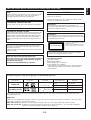
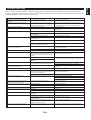
The Video CD player on this unit can play discs of the following types only.
Never attempt to load a disc other than above on this unit because it may cause a damage to this unit and/or other units
connected to this unit.
VIDEO CD
Video CDs are classified into two types, version 1.1 and 2.0. This unit can play not only discs of version 1.1, but also version
2.0 on which a Playback Control can be made.
Video CD, version 1.1: With the same operation as compact discs, you can enjoy sounds and pictures (movies).
Video CD, version 2.0: In addition to a normal play which is the same as discs of version 1.1, you can make a Playback
Control. (For details on Playback Control, refer to page 22.)
Type of disc
Video CD
CD
(including CD-G)
Mark printed
on the disc
Type of signal
recorded
Sound
+
Picture (Movie)
Sound
Sound
only
+
Still picture
Size (Dimension)
12 cm
8 cm (Single type)
12 cm
8 cm (Single type)
Maximum possible
play time
74 minutes
20 minutes
74 minutes
20 minutes
This unit is not disconnected from the AC power source
as long as it is connected to the wall outlet, even if this
unit itself is turned off.
In this state, this unit is designed to consume a very small
quantity of power.
GRAPHICS

E-4
FEATURES
The System
● 5 speaker Configuration
Front L, R: 75W + 75W (6Ω) RMS Output
Power, 10% THD,
1 kHz
65W + 65W (6Ω) RMS Output
Power, 1% THD,
1 kHz
Center
: 30W (8Ω) RMS Output Power,
10% THD, 1 kHz
20W (8Ω) RMS Output Power,
1% THD, 1 kHz
Rear 30W (8Ω) RMS Output Power,
10% THD, 1 kHz
20W (8Ω) RMS Output Power,
1% THD, 1 kHz
● Adjustable Display Brightness
● 2 Microphone Jacks and Mic Mixing Level
Control for Karaoke
● Echo Level and Key Level Control Capability
● Multi-Use Timer/Sleep Timer
● Automatic Power-Off Function
● 5 External Audio/Video Component
Connecting Capability
● SUBWOOFER Output Terminal Which
Passes Low Frequencies Only
● Video Output Format Selector (TV MODE)
Switch
● Remote Control Capability
Video CD Player
● 3-Disc Carousel Auto-Changer (for Playing
Back Video CDs and Compact Discs)
● PLAYXCHANGE; Disc Changing Capability
while Playing Back Another
● 20-Track Random Access Programmable
Playback
● Single Track/Entire Disc/All Disc Repeat Play
● Random-sequence Play
● Playback Control Function Available for
Video CDs, Version 2.0
● Quick Overview of a Track and a Disc with a
Touch of the DIGEST and INTRO Buttons
Tuner
● 40 Station Random Access Preset Tuning
● 40 Station Automatic Preset Tuning
Sound Field Processor Including Dolby Pro
Logic Surround Decoder
● 2 Programs for Dolby Surround Decoding
(DOLBY PRO LOGIC and DOLBY 3 STEREO)
2 Programs for Sound Field Processing
(HALL and ARENA)
4 Programs for Singing Karaoke
● Automatic Input Balance Control for Dolby
Pro Logic Surround
● 2 Center Channel Modes
(NORMAL/PHANTOM)
● Test Tone Generator for Easier Speaker
Balance Adjustment
Graphic Equalizer
● 5-Band Adjustable Graphic Equalizer
● 4 Preset Graphic Equalizer Modes
Selectable According to the Music Source
(ROCK, BLUES, RAP and JAZZ)
● 4-Sound Field and 4-Equalizer Control Mode
Storing Capability
Dolby Pro Logic Surround
This unit employs a Dolby Pro Logic Surround decoder similar
to professional Dolby Stereo decoders used in many movie
theaters. By using the Dolby Pro Logic Surround decoder,
you can experience the dramatic realism and impact of Dolby
Surround movie theater sound in your own home. Dolby Pro
Logic employs a four channel five speaker system. The Pro
Logic Surround system divides the input signal into four
levels: the left and right main channels, the center channel
(used for dialog), and the rear surround sound channels
(used for sound effects, background noise, and other ambient
noises). The center channel allows listeners seated in even
less-than-ideal positions to hear the dialog originating from
the action on the screen while experiencing good stereo
imaging.
Dolby Surround is encoded on the sound track of pre-
recorded video tapes, laser discs, and some TV/cable
broadcasts. When you play a source encoded with Dolby
Surround on this unit, the Dolby Pro Logic Surround decoder
decodes the signal and distributes the surround-sound
effects.
In addition, this unit features a built-in automatic input balance
control. This always assures you the best performance
without manual adjustment.
Manufactured under license from Dolby Laboratories
Licensing Corporation. “Dolby”, the double-D symbol and “Pro
Logic” are trademarks of Dolby Laboratories Licensing
Corporation.

E-5
English
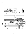
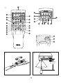
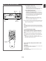
NAMES OF CONTROLS AND INDICATORS
For amplifier/tuner
(See figure 1 on page 33 at the beginning part of this
manual.)
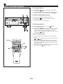
1 POWER Switch
2 PHONES Jack
3 Remote Control Sensor
4 USER Button
5 User Program MEMORY Button
6 DISPLAY Button
7 PRESET/TUNING/BAND Selector Button
8 MIC (Microphone) Jacks
9 A/B/C/D/E Button
0 MIC MIXING (Microphone Mixing) Level Control
A (Down)/ (Up) Buttons
B AUTO/MAN’L (TIMER) Button
C Tuner MEMORY (TIME ADJUST) Button
D VOLUME Control
E MIN Button
F HOUR Button
G INPUT SELECTOR
H MUSIC Button
I Equalizer Control Buttons
(ECHO Buttons)
(Key Level Control / Buttons)
J PROGRAM Selector Button
Display
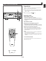
1 Preset Equalizer Mode Indicator (MUSIC)
2 Sound Field Program Indicator (PROGRAM)
3 User Program Number Indicator
4 Center Channel Mode (NOR/PHANTOM) Indicator
5 TEST Indicator
6 TIMER Set Indicator
7 SLEEP Indicator
8 AUTO Tuning Indicator
9 TUNED Indicator
@ STEREO Indicator
A MEMORY Indicator
B Volume Level Meter
C Graphic Equalizer Level Indicators
D Preset Number Indicator
E Multi Information Display
(Time, Station Frequency, Volume Level, etc.)
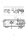
For Video CD player
(See figure 2 on page 44 at the beginning part of this
manual.)
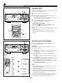
K Disc Table
L DISC Selector Buttons
M RANDOM Button
N Stop Button:
O Play/Pause Button: /
P Skip Buttons: /
(Search Buttons: / )
Q TIME Button
R REPEAT Button
S OPEN/CLOSE Button:
T DISC CHANGE Button
Display
F VIDEO CD Indicator
G PBC Indicator
H RANDOM Play Indicator
I Music Calendar Indicator
J Music Calendar OVER 15 Indicator
K Disc Indicator
L Track Number Indicator
M Time Display
N Play Indicator:
O (S, F) REPEAT Indicator
P Program (PROG) Play Indicator

E-6
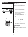
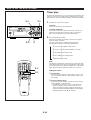
Loading the batteries for the
remote control transmitter
(See figure 4 on page 55.)
1 Remove the battery compartment cover.
(Slide the cover in the direction of the arrow.)
2 Insert 2 “AA” size batteries (UM/SUM-3, R6, HP-7 or
equivalent) into the battery compartment.
* Installing the batteries improperly may cause failure.
3 Replace the battery compartment cover.
Precautions for battery use
•
Insert the batteries according to the direction indicated in
the battery compartment.
•
Replace all batteries with new ones at the same time.
•
Remove the batteries if they are weak or if the unit is not
in use for long periods.
•
Don’t mix normal batteries with rechargeable batteries.
Proper use of the remote control
transmitter
(See figure 5 on page 55.)
Aim (within the range of 60° with no obstacles) the remote
control transmitter at the remote control sensor and operate
as shown.
Notes concerning use
•
Replace the batteries if control distance decreases or
operation becomes unstable.
•
Periodically clean the transmitter window on the remote
control transmitter and the sensor on the main unit with a
soft cloth.
•
Exposing the sensor on the main unit to strong light
(especially an inverter type of fluorescent lamp etc.) may
interfere with operation. In this case, reposition the main
unit to avoid direct lighting.
•
Keep the remote control transmitter away from moisture,
excessive heat, shock and vibrations.
•
The remote control transmitter’s usable range is within
0.2m (8”) and 6m (20’) away from the sensor.
Names of control buttons
(See figure 3 on page 55 at the beginning part of this
manual.)
■
Amplifier/tuner control buttons
1 Remote Control Transmitter Window
2 Preset Station Number Buttons
3 A, B, C, D, E Selector Buttons
4 LEVEL Control Buttons
5 CENTER/REAR/DELAY Selector Button
(ECHO/KEY Selector Button)
6 TEST Button
7 MUSIC Button
8 PROGRAM Button
9 SLEEP Button
0 VOLUME – (Down)/+ (Up) Buttons
A POWER Switch
B DISPLAY Button
C USER Button
D FLAT Button
E INPUT Selector Buttons
F TUNER Input Selector Button
G PRESET Number (Down)/ (Up) Buttons
■ Video CD player control buttons
H Track Number Input Buttons
I TIME Button
J PROGRAM Button
K Disc Play MODE Selector Button
L DISC SKIP Button
M INDEX Buttons
N Skip Buttons: /
(Search Buttons: / )
(PREV/NEXT Buttons)
O Stop Button:
(RETURN Button)
P Play/Pause Button: /
(SELECT Button)
Q OPEN/CLOSE Button:
R TIME INDEX Buttons
S DIGEST Button
T INTRO Button
REMOTE CONTROL TRANSMITTER

E-7
English
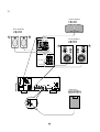
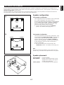
SETTING UP THE SPEAKERS
This unit designed to provide the best sound-field quality with a 5-speaker configuration: front speakers, rear speakers and a
center speaker. You may omit the center speaker, if for some reason it is not practical to use a center speaker. (Refer to the “4-
Speaker Configuration” shown below.)
The front speakers are used for the main source sound plus the effect sounds. The rear speakers are used for the effect and
surround sounds, and the center speaker is for the center sounds (dialog etc.).
(1)
(2)
Front R
Center
Front L
TV set
Rear R
Rear L
Speaker configuration
(1)5-Speaker Configuration
This configuration is the most effective and recommended
one. In this configuration, the center speaker is
necessary as well as the rear speakers. If the sound field
program DOLBY PRO LOGIC or DOLBY 3 STEREO is
selected, conversations will be output from the center
speaker and the ambience will be excellent.
● Set the center channel mode to the “NORMAL”
position. (For details, refer to page 12.)
(2)4-Speaker Configuration
The center speaker is not used in this configuration. If the
sound field program DOLBY PRO LOGIC is selected, the
center sound is output from the left and the right front
speakers, although the program DOLBY 3 STEREO is
useless in this configuration. However, the sound effect
of other programs can be the same as that of the 5-
speaker configuration.
● Be sure to set the center channel mode to the
“PHANTOM” position. (For details, refer to page 12.)
Note
Be sure to use two rear speakers. If you connect one rear
speaker only, sound will not be output from the rear speaker.
Speaker placement
Front speakers: In normal position.
Rear speakers: Behind your listening position, facing
slightly inward. Nearly 1.8 m (approx.
six feet) up from the floor.
Center speaker: Precisely between the front speakers.
Front L Center Front R
Dialogue
Surround sound
Dialogue
Surround sound
Rear L
Rear R
Front L Front R
Dialogue
Surround sound
Dialogue
Surround sound
Rear L Rear R

E-8
ANTENNA
AM
FM
GND
75
Ω
UNBAL.
ANTENNA
AM
FM
GND
75
Ω
UNBAL.
(1)
(2)
(3)
(4)
ANTENNA
AM
FM
GND
75
Ω
UNBAL.
NORMALAUTO
50kHz
9kHz
10kHzNTSC
100kHz
FM
AM
PHANTOMPAL
CENTER
MODE
TV
MODE
FREQUENCY
STEP
VCR MONITOR
OUT
D
EO SIGNAL
ANTENNA
AM
FM
GND
75
Ω
UNBAL.
N
OUT
E
O SIGNAL
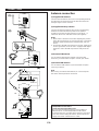
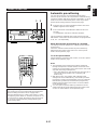
Antenna connection
(1) Supplied FM antenna
Connect the FM antenna wire to the corresponding terminal
and direct the FM antenna wire to the direction where the
strongest signal can be received.
(2) Supplied AM loop antenna
Connect the AM loop antenna wires to the corresponding
terminals. Position the AM loop antenna for optimum
reception. Place the AM loop antenna on a shelf etc., or
install it on the rack or wall with screws (not supplied).
Notes
•
When static is still heard even after adjusting the position
of the AM loop antenna, try reversing the wire connections
(from the upper terminal to the lower terminal, and vice
versa).
•
Do not place the AM loop antenna on the unit. It will result
in noise generation, since the unit is equipped with digital
electronics. Place the AM loop antenna away from the
unit.
(3) External FM antenna
Use an external FM antenna instead of an indoor FM
antenna if you need better reception. Consult your dealer.
(4) External AM antenna
Use an external AM antenna if you need better reception.
Consult your dealer.
Note
When using an external AM antenna, be sure to keep the
wire of the AM loop antenna connected.
CONNECTIONS
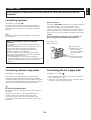
FREQUENCY STEP switch
(China and General models only)
Because the interstation frequency spacing differs in
different areas, set the FREQUENCY STEP switch
(located at the rear) according to the frequency spacing in
your area. Before setting this switch, disconnect the AC
supply lead of this unit from the AC outlet.
or
15 m (49 feet)
7.5 m (25 feet)
Earth rod

E-9
English
CONNECTIONS
Connecting speakers
(See figure 6 on page 66.)
Connect the front speakers to the FRONT SPEAKERS
terminals, the center speaker to the CENTER SPEAKERS
terminals and the rear speakers to the REAR SPEAKERS
terminals.
Note
Use speakers with the specified impedance shown on the
rear of this unit.
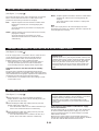
How to Connect:
Connect the SPEAKERS terminals to your speakers with wire
of the proper gauge, cut as short as possible. If the
connections are faulty, no sound will be heard from the
speakers. Make sure that the polarity of the speaker wires is
correct, that is the + and – markings are observed. If these
wires are reversed, the sound will be unnatural and lack bass.
Caution
Do not let the bare speaker wires touch each other as
this could damage the amplifier and/or speakers.
Red: positive (+)
Black: negative (–)
➀
Press up the tab.
➁
Insert the bare wire.
[Remove approx.
5mm (1/4”) insulation
from the speaker
wires.]
➂
Press down the tab
and secure the wire.
➀
➁
➂
Never plug the AC supply lead of this unit into the AC outlet until all connections are
completed.
Note on connecting a subwoofer (separate
purchase)
You may wish to add a subwoofer to reinforce the bass
frequencies.
Connect the SUBWOOFER OUT terminal on the rear of
this unit to the INPUT terminal of the subwoofer
amplifier, and connect the speaker terminals of the
subwoofer amplifier to the subwoofer.
With some subwoofers, including the Yamaha Active
Servo Processing Subwoofer System, the amplifier and
subwoofer are in the same unit.
* The SUBWOOFER OUT terminal is for output to a
monaural amplifier driving a subwoofer. Only frequencies
below 200 Hz from the front and center channels are
output.
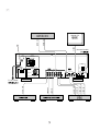
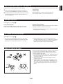
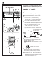
Connecting external components
(See figure 7 on page 77.)
This unit can be connected with external audio and video
components. Make connections between this unit and other
components using RCA pin plug connector cables correctly, that
is to say L (left) to L and R (right) to R. Also, refer to the owner’s
manual for each component to be connected to this unit.
AC OUTLET (UNSWITCHED)
The power cord of any audio/video unit can be connected to
this outlet.
The power to this outlet is not controlled by this unit’s
POWER switch. This outlet will supply power to the
connected unit even if this unit is in the standby mode.
The maximum power that can be connected to this outlet is
100 watts.
Connecting the AC supply lead
(See figure 8 on page 88.)
•
After completing all connections, plug the AC supply lead
into a convenient AC outlet.
•
Unplug the AC supply lead from the AC outlet if the unit is
not to be used for a long period of time.
*

E-10
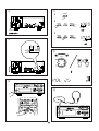
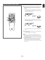
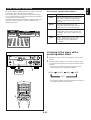
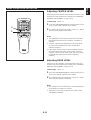
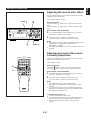
SETTING THE CLOCK
(See figure A on page 88.)
1 While the power is on, press the DISPLAY button to
display the time. If this unit is into the standby mode, you
can proceed to the next step.
2 While holding the TIME ADJ button pressed, press the
HOUR button and set the hour.
* Press the HOUR button once to advance the time by 1
hour. Press and hold to advance continuously.
3 While holding the TIME ADJ button pressed, press the
MIN button and set the minute.
* Press the MIN button once to advance the time by 1
minute. Press and hold to advance continuously.
Singapore model uses a 24-hour display. China and
General models use either a 24-hour display or a 12-hour
display [shown by “AM (PM) 12:00”] is selected
depending on the setting of the FREQUENCY STEP
switch on the rear panel, so you cannot select a desired
type freely.
In the event of a power failure or when the AC supply
lead is disconnected.
The time display will go out, however, the clock will function
for about 5 minutes without power supply. So you do not
have to reset the time if the AC power supply is resumed
within about 5 minutes.
When the AC power supply is resumed after more than 5
minutes pass without power supply, the time display will flash
on and off to indicate that the time must be reset.
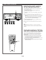
TURNING THE POWER TO THIS UNIT ON OR IN THE STANDBY MODE
(See figure 0 on page 88.)
If the AC supply lead is connected to the AC outlet, this unit
can be turned on and turned into the standby mode by
pressing the POWER switch on the front panel or the
POWER switch on the remote control transmitter.
•
While the power is on, the display shows the name of
currently selected input source or other information.
In the standby mode, the display shows only the time.
Automatic function to turn this unit into the standby
mode
The power of this unit will be automatically turned into the
standby mode if there is no operation on the control parts of this
unit, no illumination on the graphic equalizer level indicators and
no playback of Video CD (CD) for about 30 minutes.
* This function is not available unless time setting is made
on the built-in clock.
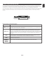
(See figure 9 on page 88.)
The Video CD player on this unit is designed for use with the
NTSC and PAL television formats. Set this switch to the
position for the format your monitor TV employs.
PAL: Outputs signals in the PAL format no matter which
format (PAL or NTSC) the currently playing disc
employs.
Set to this position if your monitor TV employs the
PAL format.
AUTO: Outputs signals in the same format as the currently
playing disc employs.
Set to this position if your monitor TV can be
switched in between the PAL and NTSC formats
automatically.
NTSC: Outputs signals in the NTSC format no matter which
format (PAL or NTSC) the currently playing disc
employs.
Set to this position if your monitor TV employs the
NTSC format.
Note
Make sure to play back a disc which employs the same
format that your monitor TV employs, otherwise a picture will
not be played back normally.
SETTING THE VIDEO OUTPUT FORMAT SELECTOR (TV MODE) SWITCH
Standby mode
While the power is on, pressing the POWER switch (or the
POWER switch on the remote control transmitter) switches
this unit to the Standby mode. (In this mode, the display
shows only the time.) In this mode, main voltage is still
present inside this unit. If you want to switch off this unit
completely, disconnect the AC power plug from the AC
outlet.

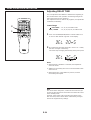
E-11
English
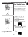
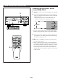
If desired, you can adjust brightness of the display.
1 Press and hold the DISPLAY button for more than 2
seconds so that “DIMMER±0” appears on the display.
2 Holding the DISPLAY button pressed, turn the VOLUME
control clockwise to increase or counterclockwise to
decrease brightness.
This adjustment can be made even though this unit is in the
standby mode.
Control range
When the power is on: ±0 to –6 (Preset value: ±0)
In the standby mode: +3 to –3 (Preset value: ±0)
ADJUSTING BRIGHTNESS OF THE DISPLAY
(See figure B on page 88.)
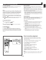
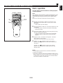
Front panel operation
Rotate the VOLUME control clockwise to increase the
volume, and counterclockwise to decrease the volume.
Remote control operation
Press the VOLUME + button to increase the volume and the
VOLUME – button to decrease the volume.
* Adjusted volume level is shown by the volume level meter
and in figures on the display.
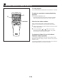
VOLUME CONTROL
(See figure C on page 88.)
•
Be sure that your headphones have a 3.5 mm (1/8”)
diameter plug and are between 16 ohms and 50 ohms
impedance. Recommended impedance is 32 ohms.
•
When headphones are connected, the speakers are
defeated automatically and you can listen to the sound to
be output from the front speakers through headphones.
Adjust the VOLUME control for desired volume.
LISTENING WITH HEADPHONES
Discs are fairly resistant to damage, however mistracking can
occur due to an accumulation of dirt on the disc surface.
Follow the guidelines below for maximum enjoyment from
your disc collection and player.
•
Do not write on either side of the disc, particularly the non-
label side. Signals are read from the non-label side. Do
not mark this surface.
•
Keep your discs away from direct sunlight, heat and
excessive moisture.
•
Always hold the discs by the edges. Fingerprints, dirt or
water on the discs can cause noise or mistracking. If a
disc is dirty or does not play properly, clean it with a soft,
dry cloth, wiping straight out from the center, along the
radius.
CARE OF VIDEO CDS (CDS)

E-12
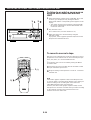
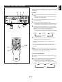
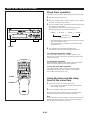
SPEAKER BALANCE ADJUSTMENT
SPEAKERS
CENTER/REAR
VOLTAGE
SELECTOR
SPEAKERS
FRONT
AC OUTLET
MAINS
R L
CENTERREAR REAR
REAR SINGLE
CENTER :8
Ω
MIN./SPEAKER
6
Ω
MIN./SPEAKER
SEE OWNER'S MANUAL FOR CONNECTION.
SEE OWNER'S MANUAL FOR CONNECTION.
REAR
:4
Ω
MIN./SPEAKER
REAR SINGLE
:8
Ω
MIN./SPEAKER
RL
L
UNSWITCHED
100W MAX.
AUDIO SIGNAL
AUX
TAPE
•
MD LD
•
TV
AUDIO SIGNAL
VCR SUBWOOFER
R
IN OUT IN OUT
OUT
VCR MONITOR
OUT
LD
•
TV
VIDEO SIGNAL
ANTENNA
AM
FM
GND
75
Ω
UNBAL.
NORMALAUTO
50kHz
9kHz
10kHzNTSC
100kHz
FM
AM
PHANTOMPAL
CENTER
MODE
TV
MODE
FREQUENCY
STEP
IN OUT
VIDEO SIGNAL
NORMAL
PHANTOM
CENTER
MODE
NORMALAUTO
50kHz
9kHz
10kHzNTSC
100kHz
FM
AM
PHANTOMPAL
CENTER
MODE
TV
MODE
FREQU
PHONES
POWER
DISC
123
PROGRAM
ECHO ECHO
MUSIC
USER
MEMORY
INPUT SELECTOR
VCR/LD-TV/VCD-CD/TUNER/TAPE•MD/AUX
VOLUME
RANDOM
DISPLAY
MIC
MIN MAX
MIC MIXING
REPEAT TIME MEMORY AUTO/MAN'L
HOUR
PRESET/TUNING/BAND
A/B/C/D/E
MIN TIME ADJ TIMER
OPEN/
CLOSE
DISC
CHANGE
VIDEO CD
Version 2.0
/
Playback Control
TIME
A
PROG
B C D
+I0
E
VCD/CD
1
1
2
2
3
3
4
4
5
5
6
6
7
7
8
8
9 0
PRESET
INPUT
TIME INDEX
INTRO DIGEST
POWER
DISPLAY
SLEEP
MUSIC
FLAT
PROGRAM
USER
VOLUME
DISC SKIP
RETURN
PREV NEXT
SELECT
LEVEL
TEST
CENTER/REAR
/DELAY
ECHO/
KEY
OPEN/CLOSE
INDEXMODE
TUNER
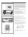
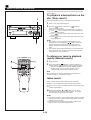
This procedure lets you adjust the sound output level balance
between the front, center, and rear speakers using the built-in
test tone generator. When this adjustment is performed, the
sound output level heard at the listening position will be the
same from each speaker. This is important for the best
performance of the built-in Dolby Pro Logic surround decoder.
The adjustment of each speaker output level should be
done at your listening position with the remote control
transmitter. Otherwise, the result may not be satisfactory.
Before operation
Set the CENTER MODE switch on the rear panel of this unit
to the position suitable for your speaker system configuration.
(Refer to page 7 for details.)
NORMAL (For 5 speaker configuration):
Select this position when you use the center speaker.
PHANTOM (For 4 speaker configuration):
Select this position when you do not use the center
speaker. The center sound will be output from the left
and right front speakers.
1 Press the POWER switch to turn the power on.
2 Turn the VOLUME control fully counterclockwise to
decrease the volume to minimum.
3 Press the PROGRAM button once or more so that “
PRO LOGIC” lights up on the sound field program
indicator.
4 Press the TEST button.
* “TEST” flashes on and off on the display.
5 Press the VOLUME + (up) button to increase the volume.
You will hear a test tone (like pink noise) from the left front
speaker, then the center speaker, then the right front
speaker, and then the rear speakers, for about two seconds
each. The display changes as shown below.
* The test tone from the left rear speaker and the right rear
speaker will be heard at the same time.
(L and R)
4
3
1
5
2
3
1
2, 5
La pagina si sta caricando...
La pagina si sta caricando...
La pagina si sta caricando...
La pagina si sta caricando...
La pagina si sta caricando...
La pagina si sta caricando...
La pagina si sta caricando...
La pagina si sta caricando...
La pagina si sta caricando...
La pagina si sta caricando...
La pagina si sta caricando...
La pagina si sta caricando...
La pagina si sta caricando...
La pagina si sta caricando...
La pagina si sta caricando...
La pagina si sta caricando...
La pagina si sta caricando...
La pagina si sta caricando...
La pagina si sta caricando...
La pagina si sta caricando...
La pagina si sta caricando...
La pagina si sta caricando...
La pagina si sta caricando...
La pagina si sta caricando...
La pagina si sta caricando...
La pagina si sta caricando...
La pagina si sta caricando...
La pagina si sta caricando...
La pagina si sta caricando...
La pagina si sta caricando...
La pagina si sta caricando...
-
 1
1
-
 2
2
-
 3
3
-
 4
4
-
 5
5
-
 6
6
-
 7
7
-
 8
8
-
 9
9
-
 10
10
-
 11
11
-
 12
12
-
 13
13
-
 14
14
-
 15
15
-
 16
16
-
 17
17
-
 18
18
-
 19
19
-
 20
20
-
 21
21
-
 22
22
-
 23
23
-
 24
24
-
 25
25
-
 26
26
-
 27
27
-
 28
28
-
 29
29
-
 30
30
-
 31
31
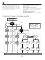
-
 32
32
-
 33
33
-
 34
34
-
 35
35
-
 36
36
-
 37
37
-
 38
38
-
 39
39
-
 40
40
-
 41
41
-
 42
42
-
 43
43
-
 44
44
-
 45
45
-
 46
46
-
 47
47
-
 48
48
-
 49
49
-
 50
50
-
 51
51


Yamaha EM-202VCD Manuale utente
- Categoria
- Ricevitore
- Tipo
- Manuale utente
in altre lingue
- English: Yamaha EM-202VCD User manual
- français: Yamaha EM-202VCD Manuel utilisateur
- español: Yamaha EM-202VCD Manual de usuario
- Deutsch: Yamaha EM-202VCD Benutzerhandbuch
- русский: Yamaha EM-202VCD Руководство пользователя
- Nederlands: Yamaha EM-202VCD Handleiding
- português: Yamaha EM-202VCD Manual do usuário
- dansk: Yamaha EM-202VCD Brugermanual
- čeština: Yamaha EM-202VCD Uživatelský manuál
- polski: Yamaha EM-202VCD Instrukcja obsługi
- svenska: Yamaha EM-202VCD Användarmanual
- Türkçe: Yamaha EM-202VCD Kullanım kılavuzu
- suomi: Yamaha EM-202VCD Ohjekirja
- română: Yamaha EM-202VCD Manual de utilizare
Documenti correlati
-
Yamaha EM-203VCD Manuale utente
-
-
-
-
-
-
-
-
-