
363511
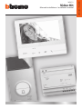
Video Kit
Manuale installatore • Installation manual
LE09435AC-1PC-20W01

2
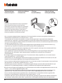
Attenzione: le operazioni di installazione, configurazione, messa in servizio e manutenzione devono
essere effettuate da personale qualificato.
Caution: installation, configuration, starting-up and maintenance must be performed by qualified personnel.
Attention: les opérations d’installation, de configuration, de mise en service et d’entretien doivent
être confiées à un personnel qualifié.
Achtung: die Installation, Konfiguration, Inbetriebnahme und Wartung dürfen nur von qualifizierten
Fachleuten vorgenommen werden.
Atención: las operaciones de instalación, configuración, puesta en servicio y mantenimiento han de
ser efectuadas por personal cualificado.
Opgelet: laat de installatie, de configuratie, de inbedrijfstelling en het onderhoud door gekwalificeerd
personeel verrichten.
Atenção: As operações de instalação, configuração, colocação em serviço e manutenção devem ser
realizadas por pessoal qualificado.

Video Kit
3
230 Vac 12 V
230 Vac
230 Vac 12 V
230 Vac
*
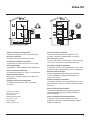
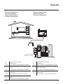
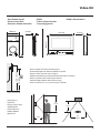
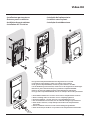
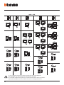
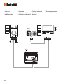
• Vecchio impianto a campanello
Impianto esistente con 3 fili e sola chiamata.
• Old system with bell
Existing system with 3 wires and just call.
• Ancienne installation a sonnette
Installation existante à 3 fils et un seul appel.
• Alte klingelanlage
Vorhandene 3-Leiter Anlage nur mit Ruffunktion.
• Vieja instalación con timbre
Instalación existente con 3 hilos y una llamada.
• Oude deurbelinstallatie
Bestaande 3-aderige installatie met alleen een
oproepfunctie.
• Antiga instalação em campaínha
Instalação existente com 3 fios e somente
chamada.
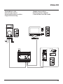
• Nuovo impianto citofonico
Impianto realizzato senza modifiche ai 2 fili
esistenti: chiamata, videocitofono e serratura.
• New door entry system
System made without modifications to the 2 existing
wires; call, video handset and electric door lock.
• Nouvelle installation phonique
Installation réalisée sans modifications sur les 2 fils
existants: appel, vidéophone, et serrure électrique.
• Neue haustelefonanlage
Anlage ohne Änderungen an den vorhandenen
2 Leiter: Ruffunktion, Gegensprechanlage und
elektrisches Schloss.
• Nueva instalación interfónica
Instalación realizada sin las modificaciones a los 2
hilos existentes: llamada, videoportero y cerradura
eléctrica.
• Nieuwe deurtelefooninstallatie
Installatie aangelegd zonder wijzigingen aan de
2 bestaande aders: oproep, beeldhuistelefoon en
elektrisch deurslot.
• Nova instalação do intercomunicador
Instalação realizada sem modificar os 2 fios
existentes: chamada, intercomunicador vídeo e
fechadura eléctrica.
* Acquistabile separatamente
* Can be purchased separately
* Vendu séparément
* Auf Anfrage getrennt erhältlich
* A la venta por separado
* Apart verkrijgbaar
* Adquirível separadamente

4
D
B C
A
>0,2 mm
2
BTicino
L4669
0,35 mm
2
0,28 mm
2
BTicino
C9881U/5E
AWG24 UTP5
BTicino
336904
One PTT
278 TP
0,28 mm
2
OneSYT
+ Digital
TP
5/10
OneSYT
+ Num
TP
5/10
GIGA TW
CAT5E
AWG24
One SYT
+ Num TP
8/10
Cable
ARB.6060-1
6/10
Cable
EV6R
6/10
1
mm
2
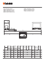
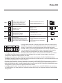
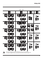
A 50 m 140 m 145 m 200 m 200 m 145 m 200 m 50 m –
B 50 m 115 m 80 m 200 m 115 m 80 m 200 m 50 m –
C 50 m 100 m 65 m 200 m 100 m 65 m 200 m 50 m –
D 30 m 30 m – 50 m 30 m – – –
100
m
• Cavi e distanze (mm
2
)
• Cables and distances (mm
2
)
• Câbles et distances (mm
2
)
• Kabeln und Abstände (mm
2
)
• Cables y distancias (mm
2
)
• Kabels en afstanden (mm
2
)
• Cabos e distâncias (mm
2
)

Video Kit
5
N
= –
= –
T = –
S = –
P
= –
–
=
ON
OFF
P
= –
= –
= –
= –
M
J2
J1
N
= –
= –
2
1
BUS
PL S+
S-
A
B
BUS5M 21 1
Bifamiliare - Two family
Monofamiliare - One family
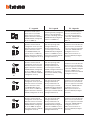
•
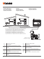
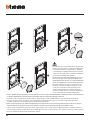
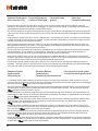
Schema monofamiliare
•
One-family diagram
•
Schéma mono-familial
•
Schema Einfamilienhaus
•
Esquema monofamiliar
•
Schema eensgezins
•
Esquema monofamiliar
• A Pulsante locale apertura serratura.
B Chiamata al piano.
S+ S- 18 V; 4 A impulsivi. 250 mA mantenimento (30 Ω max).
• A Door lock release local pushbutton.
B Floor call.
S+ S- 18 V; 4 A impulsive. 250 mA holding current (30 Ω max).
• A Bouton local ouverture serrure.
B Appel à l’étage.
S+ S- 18 V; 4 A impulsifs. 250 mA entretien (30 Ω max).
• A Lokale Schlossöffnungstaste.
B Etagenruf.
S+ S- 18 V; 4 A impulsstrom. 250 mA Haltestrom (30 Ω max).
• A Pulsador local apertura cerradura.
B Llamada al piso.
S+ S- 18 V; 4 A por impulsos. 250 mA mantenimiento (30 Ω max).
• A Lokale knop opening slot.
B Oproep aan verdieping.
S+ S- 18 V; 4 A impulsief; 250 mA onderhoud (30 Ω max).
• A Botão local de abertura da fechadura.
B Chamada ao piso.
S+ S- 18 V; 4 A instantâneos. 250 mA continuos (30 Ω max).

6
ON
OFF
ON
OFF
P
= –
= –
= –
= –
M
J2
J1
N
= –
= *1
P
= –
= –
= –
= –
M
J2
J1
N
= –
= –
BUS
PL S+
S-
N
= –
= –
T = –
S = –
P
= –
–
=
2
1
A
B
BUS5M 21 1
B
BUS5M 21 1
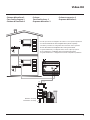
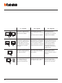
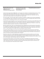
* • Il secondo posto interno ed il configuratore 3501/1 devono essere acquistati separatemente.
• The second internal unit and the 3501/1 configurator must be purchased separately.
• Le deuxième poste interne et le configurateur 3501/1 doivent être achetés séparément.
• Die zweite Hausstation und der Konfigurator 3501/1 werden getrennt verkauft.
• La segunda unidad interior y el configurador 3501/1 se han de comprar por separado.
• De tweede binnenpost en de configurator 3501/1 moeten apart worden gekocht.
• A segunda unidade interna e o configurador 3501/1 devem ser adquiridos separadamente.
*
Bifamiliare - Two family
Monofamiliare - One family
• Schema bifamiliare
• Two-family diagram
• Schéma bi-familiale
• Schema
Zweifamilienhaus
• Esquema bifamiliar
• Schema tweegezins
• Esquema bifamiliar
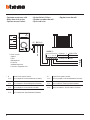
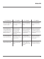
• A Pulsante locale apertura serratura.
B Chiamata al piano.
S+ S- 18 V; 4 A impulsivi. 250 mA mantenimento (30 Ω max).
• A Door lock release local pushbutton.
B Floor call.
S+ S- 18 V; 4 A impulsive. 250 mA holding current (30 Ω max).
• A Bouton local ouverture serrure.
B Appel à l’étage.
S+ S- 18 V; 4 A impulsifs. 250 mA entretien (30 Ω max).
• A Lokale Schlossöffnungstaste.
B Etagenruf.
S+ S- 18 V; 4 A impulsstrom. 250 mA Haltestrom (30 Ω max).
• A Pulsador local apertura cerradura.
B Llamada al piso.
S+ S- 18 V; 4 A por impulsos. 250 mA mantenimiento (30 Ω max).
• A Lokale knop opening slot.
B Oproep aan verdieping.
S+ S- 18 V; 4 A impulsief; 250 mA onderhoud (30 Ω max).
• A Botão local de abertura da fechadura.
B Chamada ao piso.
S+ S- 18 V; 4 A instantâneos. 250 mA continuos (30 Ω max).

Video Kit
7
BUS
PL S+
S-
ON
OFF
ON
OFF
P
= –
= –
= –
= –
M
J2
J1
N
= –
= *1
P
= –
= –
= –
= –
M
J2
J1
N
= –
= –
N
= –
= –
T = –
S = –
P
= –
–
=
2
1
A
B
BUS5M 21 1
B
BUS5M
2
1
1
*
Bifamiliare - Two family
Monofamiliare - One family
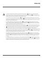
* • Il secondo posto interno ed il configuratore 3501/1 devono essere acquistati separatemente.
• The second internal unit and the 3501/1 configurator must be purchased separately.
• Le deuxième poste interne et le configurateur 3501/1 doivent être achetés séparément.
• Die zweite Hausstation und der Konfigurator 3501/1 werden getrennt verkauft.
• La segunda unidad interior y el configurador 3501/1 se han de comprar por separado.
• De tweede binnenpost en de configurator 3501/1 moeten apart worden gekocht.
• A segunda unidade interna e o configurador 3501/1 devem ser adquiridos separadamente.
• Schema bifamiliare 2
• Two-family diagram 2
• Schéma bi-familiale 2
• Schema
Zweifamilienhaus 2
• Esquema bifamiliar 2
• Schema tweegezins 2
• Esquema bifamiliar 2

8
BUSPL S+
S-
N
= –
= –
T = –
S = –
P
= –
–
=
8 A cosφ = 1
4 A cosφ = 0,7
3 A cosφ = 0,4
24 Vdc; 24 Vac
24 Vac
24 Vac
NO
NC
C
346250 (*)
S-
S+
C
NC
NO
A
* • Fornito a corredo.
• Supplied.
• Fourni.
• Wird mitgeliefert.
• En dotación.
• Standaard meegeleverd.
• Fornecido no equipamento base.
• Opzione serratura a relè
• Relay door lock option
• Option serrure à relais
• Option Relais-Schloss
• Opción cerradura de relé
• Optie relaisslot
• Opção trinco de relê
• A Pulsante locale apertura serratura.
S+ S- 18 V; 4 A impulsivi. 250 mA mantenimento (30 Ω max).
• A Door lock release local pushbutton.
S+ S- 18 V; 4 A impulsive. 250 mA holding current (30 Ω max).
• A Bouton local ouverture serrure.
S+ S- 18 V; 4 A impulsifs. 250 mA entretien (30 Ω max).
• A Lokale Schlossöffnungstaste.
S+ S- 18 V; 4 A impulsstrom. 250 mA Haltestrom (30 Ω max).
• A Pulsador local apertura cerradura.
S+ S- 18 V; 4 A por impulsos. 250 mA mantenimiento (30 Ω max).
• A Lokale knop opening slot.
S+ S- 18 V; 4 A impulsief; 250 mA onderhoud (30 Ω max).
• A Botão local de abertura da fechadura.
S+ S- 18 V; 4 A instantâneos. 250 mA continuos (30 Ω max).

Video Kit
9
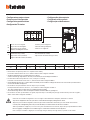
194 mm
162 mm
25 mm
100 mm
190 mm
26 mm
• Altezza consigliata salvo diversa normativa vigente.
• Recommended height, unless different regulations are specified.
• Hauteur conseillée sauf autre norme en vigueur.
• Empfohlene Höhe falls die gesetzlichen Vorschriften nichts anderes vorschreiben.
• Altura recomendada salvo normativa vigente diferente.
• Aanbevolen hoogte behoudens andere normen in voege.
• Altura aconselhada a não ser se a norma em vigor for diferente.
160 – 165 cm
90–130 cm
• Dati dimensionali
• Dimensional data
• Données dimensionnelles
• Maße
• Datos dimensionales
• Formaatgegevens
• Dados dimensionais
• Campo di ripresa
• Field of view
• Éclairage cadrage caméra
• Aufnahmebereich
• Campo de filmación
• Campo de filmagem
• Opnameveld
50 cm
105°
140 cm
80°
115 cm
50cm

10
1
2
3
4
4
5
6
15
14
13
11
12
10
9
8
7
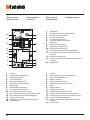
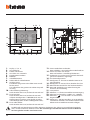
1 - Telecamera
2 - LED illuminazione campo di ripresa
3 - Morsetti di collegamento
4 - Pulsanti di chiamata
5 - LED connessione attiva
6 - LED indicazione porta aperta
7 - Microfono
8 - Regolazione microfono
9 - Regolazione altoparlante
10 - Switch mono/bifamiliare
11 - Pulsante programmazione badge/Reset
12 - Pannello LED per illuminazione pulsante di
chiamata
13 - Sede dei configuratori
14 - Sensore di luminosità per retroilluminazione
notturna
15 - Altoparlante
1 - Caméra
2 - Voyant éclairage champ de cadrage
3 - Bornes de branchement
4 - Boutons d’appel
5 - Voyant connexion active
6 - Voyant indication porte ouverte
7 - Micro
8 - Réglage micro
9 - Réglage haut-parleur
10 - Commutateur mono/bi-familial
11 - Bouton de programmation badge/Reset
12 - Panneau Voyant d’éclairage bouton d’appel
13 - Logement des configurateurs
14 - Capteur de luminosité pour rétro-éclairage
nocturne
15 - Haut-parleur
1 - Camera
2 - Viewing field lighting LED
3 - Connection clamps
4 - Call pushbuttons
5 - Active connection LED
6 - Open door notification LED
7 - Microphone
8 - Microphone adjustment
9 - Loudspeaker adjustment
10 - One-family/two-family switch
11 - Key card programming pushbutton / Reset
12 - LED panel for call pushbutton lighting
13 - Configurator socket
14 - Brightness sensor for night backlighting
15 - Loudspeaker
• Posto esterno
• Entrance panel
• Poste extérieur
• Türstation
• Placa exterior
• Externe plaats
• Unidade externa

Video Kit
11
1 - Camera
2 - Led verlichting camerabereik
3 - Aansluitklemmen
4 - Oproepknoppen
5 - LED verbinding geactiveerd
6 - LED aanduiding deur geopend
7 - Microfoon
8 - Regeling microfoon
9 - Regeling luidspreker
10 - Schakelaar een-/tweegezins
11 - Knop badgeprogrammering/reset
12 - LED paneel voor verlichting oproepknop
13 - Plaats van de configuratoren
14 - Lichtsensor voor achtergrondverlichting ‘s
nachts
15 - Luidspreker
1 - Kamera
2 - LED Beleuchtung des Aufnahmefelds
3 - Anschlussklemmen
4 - Ruftasten
5 - LED Verbindung aktiv
6 - LED Anzeige Tür offen
7 - Mikrophon
8 - Einstellung des Mikrophons
9 - Einstellung des Lautsprechers
10 - Switch Ein-/Zweifamilienhaus
11 - Programmierungstaste Badge/Reset
12 - LED-Tafel zur Beleuchtung der Ruftaste
13 - Sitz der Konfiguratoren
14 - Helligkeitssensor zur nächtlichen
Rückbeleuchtung
15 - Lautsprecher
1 - Câmara de vídeo
2 - LED de iluminação do campo de filmagem
3 - Bornes de conexão
4 - Botões de chamada
5 - LED de conexão ativa
6 - LED indicação de porta aberta
7 - Microfone
8 - Regulação do microfone
9 - Regulação do altifalante
10 - Interruptor mono/bifamiliar
11 - Botão de programação do Crachá/Rearme
12 - Painel LED para iluminação do botão de
chamada
13 - Sede dos configuradores
14 - Sensor de luminosidade para retroiluminação
noturna
15 - Altifalante
1 - Telecámara
2 - LED iluminación campo de grabación
3 - Bornes de conexión
4 - Pulsadores de llamada
5 - LED conexión activada
6 - LED indicación puerta abierta
7 - Micrófono
8 - Regulación del micrófono
9 - Regulación del altavoz
10 - Switch mono/bifamiliar
11 - Pulsador de programación credencial/Reset
12 - Panel LED para iluminación pulsador de
llamada
13 - Alojamiento de los configuradores
14 - Sensor de luminosidad para retroiluminación
nocturna
15 - Altavoz

12
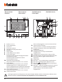
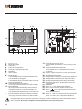
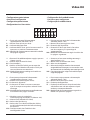
• Posto interno
• Handset
• Poste interne
• Hausstation
• Unidad interior
• Intern punt
• Unidade interna
1 2 3 4 5 6
14
13
15
891011128
7 16
19
20
21
21
18
22232425
17
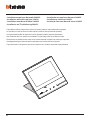
L’immagine rappresenta il dispositivo con tutte le funzioni abilitate. Verifica sul manuale installatore come
abilitare le funzioni. I manuali completi sono disponibili sul sito: www.bticino.com
1 - Display 7” (16 : 9)
2 - Tasto spegnimento
3 - Data e ora
4 - Esclusione suoneria
5 - Attivazione Studio professionale
6 - Microfono
7 - Azioni rapide
8 - Guide tattili per non vedenti
9 - Tasto connessione:
l’accensione del led verde lampeggiante indica
una chiamata in arrivo
l’accensione del led verde fisso indica la
comunicazione in corso
10 - Autoaccensione/Ciclamento:
alla pressione del tasto il LED rosso si accende
11 - Tasto Preferiti:
alla pressione del tasto il LED rosso si accende
(Configurazione base = LUCE SCALE. Per una
diversa configurazione fare riferimento alla tabella
della configurazione fisica alle pagine successive.)
12 - Tasto apertura serratura:
alla pressione del tasto il LED rosso si accende
13 - Stato presenza note:
Led rosso lampeggiante = nuova/e note non lette
14 - Stato Esclusione chiamata:
Led rosso acceso = Suoneria chiamata disattivata
15 - Funzioni (compaiono solo le icone delle funzioni
configurate)
16 - Sede dei configuratori
17 - Configuratore J1: estrai per alimentazione
supplementare
18 - Configuratore J2: Master/Slave, estrai per Slave
19 - Microinterruttore ON/OFF di terminazione di tratta
20 - Presa mini USB per aggiornamento Firmware
dispositivo
21 - Altoparlante
22 - Morsetti (1 - 2) per alimentazione supplementare
23 - Morsetti per il collegamento al BUS SCS 2 FILI
24 - Morsetti ( ) per il collegamento di un pulsante
esterno di chiamata al piano
25 - Morsetti (1 - 5M) per il collegamento di una suoneria
supplementare. Devi effettuare il collegamento
punto - punto sui morsetti delle suonerie
supplementari

Video Kit
13
The image shows the device with all its functions enabled. Check on the Installer Manual how to enable the
functions. The complete manuals are available on the website: www.bticino.com
1 - 7” (16 : 9) display
2 - OFF key
3 - Date and time
4 - Bell exclusion
5 - Office activation
6 - Microphone
7 - Quick actions
8 - Tactile guides for the blinds
9 - Connection key:
The green LED flashes to indicate an incoming call
The green LED comes on steady to indicate that
there is an active call
10 - Auto-switching on/Cycling:
The red LED turns on when the key is pressed
11 - Favorites Key:
The red LED turns on when the key is pressed
(Basic configuration = STAIRCASE LIGHT. For
a different configuration refer to the physical
configuration table in the following pages.)
12 - Door lock release key:
The red LED turns on when the key is pressed
13 - Message status:
Red LED flashing = new unread note/s
14 - Call Exclusion Status:
Red LED on = Call bell disabled
15 - Functions (only the icons for the configured
functions are displayed)
16 - Configurator seat
17 - Configurator J1: remove for additional power
supply
18 - J2 configurator: Master/Slave, remove for Slave
19 - Line termination ON/OFF micro-switch
20 - Mini USB socket for device Firmware update
21 - Loudspeaker
22 - Additional power supply clamps (1 - 2)
23 - 2 WIRE SCS/BUS connection clamps
24 - Clamps ( ) for the connection of an external
call to the floor pushbutton
25 - Additional bell connection clamps (1 - 5M) Point-
to-Point connections are required on the clamps
of the additional bells
1 -
Écran 7” (16:9)
2 -
Touche d’extinction
3 -
Date et heure
4 -
Exclusion sonneries
5 -
Activation Bureau
6 -
Micro
7 -
Actions rapides
8 -
Guides tactiles pour non-voyants
9 -
Touche connexion :
l’allumage du voyant vert clignotant indique la
présence d’un appel entrant
l’allumage du voyant vert fixe indique la
communication en cours
10 -
Auto-allumage/Cyclage :
à la pression sur la touche le VOYANT rouge s’allume
11 -
Touche Favoris :
à la pression sur la touche le VOYANT rouge s’allume
(Configuration de base = LUMIÈRE ESCALIER. Pour une
configuration différente, faire référence au tableau de
la configuration physique dans les pages suivantes.)
12 -
Touche d’ouverture serrure:
à la pression sur la touche le VOYANT rouge s’allume
13 -
État présence notes :
Voyant rouge clignotant = nouvelle(s) note(s) non lue(s)
14 -
État Exclusion appel:
Voyant rouge allumé = Sonnerie appel désactivée
15 -
Fonctions (seules les icônes des fonctions
configurées s’affichent)
16 -
Logement configurateurs
17 -
Configurateur J1 : extraire pour alimentation
supplémentaire
18 -
Configurateur J2: Master/Slave, extraire pour Slave
19 -
Microinterrupteur ON/OFF de terminaison de ligne
20 -
Prise miniUSB de mise à jour Firmware dispositif
21 -
Haut-parleur
22 -
Bornes (1 – 2) d’alimentation supplémentaire
23 -
Bornes de branchement au BUS SCS 2 FILS
24 -
Bornes ( ) de branchement d’un bouton externe
d’appel à l’étage
25 -
Bornes (1 - 5M) de branchement d’une sonnerie
supplémentaire Le branchement doit être
effectué point - point sur les bornes des sonneries
supplémentaires
L’image représente le dispositif avec toutes les fonctions activées. Vérifier dans le Manuel Installateur le
mode d’activation des fonctions. Les manuels complets sont disponibles sur le site: www.bticino.com

14
Das Bild stellt eine Vorrichtung mit allen aktivierten Funktionen dar. Sehen Sie im Installationshandbuch
nach, wie die Funktionen aktiviert werden. Die vollständigen Handbücher können von dieser Webseite
herunter geladen werden: www.bticino.com
1 - Display 7” (16 : 9)
2 - Ausschalttaste
3 - Datum und Uhrzeit
4 - Ausschluss des Läutwerks
5 - Freigabe Büro-Funktion
6 - Mikrofon
7 - Schnellfunktionen
8 - Taktile Hilfe für Sehbehinderte
9 - Anschlusstaste:
Das Blinken der grünen Led meldet einen eintref-
fenden Anruf
Das Aufleuchten der grünen Led meldet Gespräch
im Gang
10 - Selbstschaltung/Taktierung:
Durch Drücken der Taste, leuchtet die rote LED auf
11 - Taste Favoriten:
Durch Drücken der Taste, leuchtet die rote LED
auf (Basis-Konfiguration = TREPPENLICHT. Um die
Konfiguration zu ändern, siehe Tabelle der physi-
schen Konfiguration auf der nachfolgenden Seite.)
12 - Taste Schlossöffner:
Durch Drücken der Taste, leuchtet die rote LED auf
13 - Status Nachrichten vorhanden:
Rote Led blinkt = neue nicht gelesene Nachricht/en
14 - Status Ausschluss des Anrufs:
Rote Led leuchtet = Anrufklingel deaktiviert
15 - Funktionen (es werden nur die Symbole der konfi-
gurierten Funktionen angezeigt)
16 - Sitz der Konfiguratoren
17 - Konfigurator J1: für eine zusätzliche Stromversor-
gung abziehen
18 - Konfigurator J2: Master/Slave, abziehen für Slave
19 - Mikroschalter ON/OFF fur den Streckenabschluss
20 - Mini-USB-Steckbuchse zur Aktualisierung der
Firmware der Vorrichtung
21 - Lautsprecher
22 -
Klemmen (1 -2) für eine zusätzliche Stromversorgung
23 - Klemmen zum Anschluss an BUS, SCS, 2-DRAHT
24 - Klemmen ( ) zum Anschluss an eine externe
Etagenruftaste
25 - Klemmen (1 - 5M) zum Anschluss an ein zusätzliches
Läutwerk Der Anschluss muss Punkt zu Punkt an den
Klemmen des zusätzlichen Läutwerks erfolgen
1 2 3 4 5 6
14
13
15
891011128
7 16
19
20
21
21
18
22232425
17

Video Kit
15
1 - Pantalla 7” (16 : 9)
2 - Tecla apagado
3 - Fecha y hora
4 - Exclusión timbre
5 - Activación Oficina Profesional
6 - Micrófono
7 - Acciones rápidas
8 - Guías táctiles para invidentes
9 - Tecla conexión:
el encendido del led verde parpadeante indica
una llamada entrante
el encendido del led verde fijo indica la comunica-
ción en curso
10 - Autoencendido/Visualización cíclica:
al presionar la tecla el LED rojo se enciende
11 - Tecla Favoritos:
al presionar la tecla el LED rojo se enciende
(Configuración base = LUZ ESCALERAS. Para una
configuración distinta, consulte la tabla de la con-
figuración física en las páginas sucesivas.)
12 - Tecla apertura cerradura:
al presionar la tecla el LED rojo se enciende
13 - Estado presencia notas:
Led rojo parpadeante = nueva/s notas no leída/s
14 - Estado Exclusión llamada:
Led rojo encendido = Timbre llamada desactivado
15 - Funciones (aparecen solamente los iconos de las
funciones configuradas)
16 - Alojamiento configuradores
17 - Configurador J1: extraiga para alimentación adi-
cional
18 - Configurador J2: Master/Slave, extraiga para Slave
19 - Microinterruptor ON/OFF terminal de tramo
20 - Toma mini USB para actualización del firmware del
dispositivo
21 - Altavoz
22 - Bornes (1 - 2) para alimentación adicional
23 - Bornes para la conexión al BUS SCS 2 HILOS
24 - Bornes ( ) para la conexión de un pulsador
externo de llamada a la planta
25 - Bornes (1 - 5M) para la conexión de un timbre adi-
cional. Ha de efectuar la conexión punto - punto
en los bornes de los timbres adicionales
La imagen representa el dispositivo con todas las funciones habilitadas. Busque en el manual del instalador
cómo habilitar las funciones. Los manuales completos están disponibles en la web: www.bticino.com
1 - Display 7” (16 : 9)
2 - Uitschakeltoets
3 - Datum en tijd
4 - Uitsluiting beltoon
5 - Activering professionele studio
6 - Microfoon
7 - Sneltoetsen
8 - Tastgeleiders voor blinden
9 - Toets verbinding:
de groene led knippert om een binnenkomende
oproep aan te geven
de groene led brandt om een lopend gesprek aan
te geven
10 - Automatische inschakeling/cyclische weergave:
bij een druk op de toets gaat de rode led branden
11 -
Toets Favorieten:
bij een druk op de toets gaat de rode led branden
(Standaardconfiguratie = TRAPHUISVERLICHTING.
Voor een andere configuratie raadpleeg de tabel met
de fysieke configuratie op de volgende pagina’s.)
12 - Toets slotontgrendeling:
bij een druk op de toets gaat de rode led branden
13 - Status notities aanwezig:
Rode led knippert = nieuwe notitie(s)
14 - Status uitsluiting oproep:
Rode led brandt = Beltoon oproep gedeactiveerd
15 - Functies (uitsluitend de iconen van de geconfigu-
reerde functies worden weergegeven)
16 - Plaats van de configuratiemodules
17 - Configurator J1: uitnemen voor extra voeding
18 - Configurator J2: Master/Slave, uitnemen voor Slave
19 - Microschakelaar ON/OFF van beëindiging traject
20 - Mini-UBS-aansluiting voor de update van de firm-
ware van het apparaat
21 - Luidspreker
22 - Aansluitklemmen (1 - 2) voor extra voeding
23 - Aansluitklemmen voor de verbinding met de SCS
2-DRAADS BUS
24 - Morsetti ( ) voor de verbinding van een ex-
terne knop op de etage
25 - Aansluitklemmen (1 - 5M) voor de verbinding
van een extra beltoon. Verricht een punt - punt
verbinding op de aansluitklemmen van de extra
beltonen
De afbeelding toont het apparaat met ingeschakelde functies. Raadpleeg de installatiehandleiding voor de
inschakeling van de functies. De complete handleidingen zijn verkrijgbaar op de website: www.bticino.com

16
1 - Ecrã 7” (16 : 9)
2 - Botão de desligar
3 - Data e hora
4 - Exclusão da campainha
5 - Ativação do Estúdio profissional
6 - Microfone
7 - Ações rápidas
8 - Guias táteis para não videntes
9 - Botão de ligar:
o acendimento do led verde intermitente indica
uma chamada em chegada
o acendimento do led verde fixo indica a comuni-
cação em andamento
10 - Autoacendimento e Ciclamento:
ao carregar no botão acende-se o LED vermelho
11 - Botão Preferido:
ao carregar no botão acende-se o LED vermelho
(Configuração básica = LUZ DAS ESCADAS. Para
uma configuração diferente, roga-se consultar a ta-
bela da configuração física nas próximas páginas.)
12 - Botão de abertura da fechadura:
ao carregar no botão acende-se o LED vermelho
13 - Estado de presença de notas:
Led vermelho intermitente = nova (s) nota (s) não
lida (s)
14 - Estado de Exclusão de chamada:
Led vermelho aceso = Campainha de chamada
desativada
15 - Funções (aparecem apenas os ícones das funções
configuradas)
16 - Alojamento configurador
17 - Configurador J1: extrai para alimentação adicional
18 - Configurador J2: Master/Slave, extrai para Slave
19 - Microinterruptor ON/OFF de término de trecho
20 - Tomada mini USB para atualização do Firmware
do dispositivo
21 - Altifalante
22 - Bornes (1 - 2) para alimentação adicional
23 - Bornes para a conexão ao BUS SCS DE 2 FIOS
24 - Bornes ( ) para a conexão de um botão exter-
no de chamada no piso
25 - Bornes (1 - 5M) para a conexão de uma campainha
adicional. Você deverá fazer a conexão – ponto a
ponto - nos bornes das campainhas adicionais
A imagem representa o dispositivo com todas as funções ativadas. Verifique no manual do instalador como
ativar as funções Os manuais completos estão disponíveis no sítio: www.bticino.com
1 2 3 4 5 6
14
13
15
891011128
7 16
19
20
21
21
18
22232425
17

Video Kit
17
4
3
5
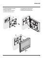
** Prima dell’installazione assicurarsi che la vite sia completamente avvitata.
** Before installing make sure that the screw is completely tightened.
** Avant l’installation, s’assurer que la vis soit complètement vissée.
** Vor der Installation sicherstellen, dass die Schraube richtig festgeschraubt ist.
** Antes de la instalación, compruebe que el tornillo esté completamente
enroscado.
** Vóór de installatie controleren of de schroef volledig vastgedraaid is.
** Antes da instalação vericar se o parafuso está completamente atarraxado.
* Per garantire l’impermeabilità montare le guarnizioni a corredo.
* To guarantee water tightness make sure to t the seals supplied.
* Pour garantir l’imperméabilité, monter les joints fournis à cet eet.
* Um die Abdichtung sicherzustellen, montieren Sie die mitgelieferten Dichtungen.
* Montar las juntas de la dotación para garantizar la impermeabilidad.
* Monteer de geleverde pakkingen om de waterdichtheid te waarborgen.
* Para garantir a impermeabilidade, montar as vedações fornecidas juntamente.
**
2
*
*
1
• Installazione posto esterno
• Entrance panel installation
•
Installation du poste extérieur
• Installation der Türstation
•
Instalación de la placa exterior
• Installatie externe plaats
•
Instalação da unidade externa

18
1
2
3
4
5
• Die Kamera darf nicht vor starken Lichtquellen oder an Orten installiert werden, wo das Subjekt sich im Gegenlicht befindet. Farbkameras besitzen bei schlechter Beleuchtung
eine geringere Empfindlichkeit als Schwarz/Weiß Kameras. Wir empfehlen daher eine zusätzliche Beleuchtungsquelle vorzusehen.
• La telecámara no debe ser instalada delante de fuentes luminosas grande en lugares en donde el individuo filmado se encuentre demasiado en contraluz. Las
telecámaras en colores presentan, en condiciones de escasa luminosidad, una sensibilidad inferior respecto a las telecámaras en blanco/negro. Por lo tanto es
aconsejable en ambientes escasamente iluminados prever una fuente de iluminación extra.
• Installeer de camera niet tegenover grote lichtbronnen of op plaatsen waar de opname van het onderwerp door sterk tegenlicht wordt gestoord. Camera’s met zijn bij een
zwakke verlichting minder gevoelig dan zwart-wit camera’s. Daarom is het raadzaam om zwak verlichte omgevingen van extra verlichting te voorzien.
• A câmara não deve ser montada diante de fortes fontes de luz, ou então em lugares onde o elemento que deve ser filmado fique muito em contraluz. As câmaras em
cores apresentam, quando há pouca luminosidade, uma sensibilidade inferior em relação às câmaras em branco e preto. Portanto, recomenda-se, quando os ambientes
forem pouco iluminados providenciar uma fonte de iluminação adicional.
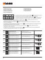
• La telecamera non deve essere installata di fronte a grandi sorgenti
luminose, oppure in luoghi dove il soggetto ripreso rimanga molto
in controluce. Le telecamere a colori presentano, in condizioni di
scarsa luminosità, una sensibilità inferiore rispetto alle telecamere
in bianco/nero. Si consiglia pertanto, in ambienti poco illuminati di
prevedere una fonte di illuminazione aggiuntiva.
• The camera must not be installed in front of large light sources, or in
places where the subject viewed remains in deep shadow. In poor
lighting conditions colour cameras are less sensitive than black/white
cameras. An extra lighting source should be added in poorly lit rooms.
• La télécaméra ne doit pas être installée en face de fortes sources
lumineuses, ou bien dans des endroits où le sujet pris reste très
à contre-jour. Les télécaméras couleurs présentent, dans des
conditions de faible luminosité, une sensibilité inférieure aux
télécaméras noir/blanc. Il est donc conseillé, dans des milieux peu
éclairés, de prévoir une source de lumière supplémentaire.

Video Kit
19
• Se si manifestasse il disturbo del fischio, (effetto Larsen), ridurre prima la potenza del microfono , agendo con un cacciavite sul potenziometro
corrispondente, fino ad un livello accettabile. Qualora il fenomeno persista, agire sul potenziometro dell’altoparlante
in modo da eliminare l’incon-
veniente. Se il volume è troppo basso, aumentare prima il volume dell’altoparlante ed eventualmente anche quello del microfono, tenendo presente che è
preferibile una trasmissione chiara e priva di disturbi, che una al limite dell’innesco (Larsen).
• In case of a whistle (Larsen effect), first reduce the microphones
power, adjusting the corresponding potentiometers with a screw driver, until an
acceptable level is reached. Should the whistle persist, adjust the loudspeakers
volume in order to eliminate the trouble. If the volume is too low level
then, increase first the potentiometer of the loudspeaker and secondly the one for the microphone, bearing in mind that a clear and noise free reception is
preferable than one just before whistling (Larsen).
• Lors de sifflement (effet de Larsen), reduire d’abord la puissance du micro sur le potentiomètre correspondant, à l’aide d’un tournevis, jusqu’à
l’obtention d’un niveau satisfaisant. Si le sifflement persiste, régler le potentiomètre du hautparleur
jusqu’à l’élimination de celui-ci. Si le volume
est trop bas, augmenter d’abord la puissance du haut-parleur et éventuellement celle du micro, en considérant qu’une réception claire et sans parasite est
préférable à une communication à la limite de l’accrochage (effet de Larsen).
• Beim etwaigen Auftreten eines Pfeiftones (Larsen-Effekt), zuerst die Lautstärke des Mikrophones bis auf einen annehmbaren Wert herabsetzen, indem
man das entsprechende Potentiometer mit einem Schraubendreher einstellt. Sollte die Störung weiterhin bestehen, dann das Potentiometer des Lautsprechers
bis zur Beseitigung des Pfeiftones einstellen. Ist die Lautstärke nun zu niedrig, dann zuerst die des Lautsprechers und erst danach evtl. auch die des
Mikrophones erhohen, wobei ein deutlicher und störungsfreier Empfang einem an der Störungsgrenze liegendem (Larsen-Effekt) vorzuziehen ist.
• Si se manifesta el silbido de acoplamiento, (efecto Larsen), reducir primero la potencia del micrófono , girando con un destornillador el potenciómetro
correspondiente, hasta obtener un nivel aceptable. Si el fenómeno persistiera, regular el potenciómetro del altavoz
hasta eliminar la interferencia. Si
el volumen es demasiado bajo, aumentar primero el volumen del altavoz y eventualmente también el del micrófono, teniendo en cuenta que es preferible
una transmissión clara y limpia de interferencias, que una al limite del acoplo (Larsen).
• Als er een fluittoon hoorbaar is (effect van Larsen): verminder eerst het vermogen van de microfoon met behulp van een schroevendraaier zijn
stroomregelaar zo te regelen dat de geluidssterkte van het gefluit aanvaardbaar is. Als het verschijnsel niet verdwijnt, dan moet u ook de stroomregelaar
van de luidspreker bijstellen. Als de geluidssterkte nu te klein is, verhoog dan eerst de geluidssterkte van de luidspreker en daarna eventueel ook die
van de microfoon, en denk er bij het bijstellen aan dat een duidelijk hoorbaar en ongestoord geluid beter is dan een harder geluid op de grens van het
Larsen effect.
• Se se manifestar uma interferência no som (efeito de Larsen), começar por diminuir a potência do microfone , rodando o potenciómetro correspon-
dente com uma chave de parafusos, até obter um nível aceitável. Se o fenómeno persistir, regular o potenciómetro do altifalante
de modo a eliminar
o problema. Se o volume estiver demasiado baixo, começar por aumentar o volume do altifalante e depois, se necessário, o do microfone, tendo presente
que é melhor ter uma transmissão clara e sem interferências, que uma no limiar de início de efeitos Larsen.

20
• Configurazione posto esterno
• Entrance panel configuration
• Configuration poste extérieur
• Konfiguration Türstation
• Configuración placa exterior
• Configuratie externe plaats
•
Configuração unidade externa
P T S N
P
- Possono non essere configurati.
- They do not need to be configured.
- Ils peuvent ne pas être configurés
- Brauchen nicht konfiguriert zu werden.
- Pueden no precisar configuración.
- Kunnen niet worden geconfigureerd.
- Podem não serconfigurados.
N
S
T
- Temporizzatore serratura (vedi tabella).
- Door lock timer relay (see table).
- Temporisation serrure (voir tableau).
- Zeitgeber schlossrelaiscerradura (siehe Tabelle).
- Temporizador relé cerradura (véase la tabla).
- Timer deurslotrelais (zie de tabel).
- Temporizador do relé da fechadura (veja a tabela).
– 1 2 3 4 5 6 7
4 s 1 s 2 s 3 s
*
6 s 8 s 10 s
* Funzionamento come pulsante per max. 10 sec. dopodichè entra in stand-by.
Per estendere tale funzionamento oltre i 10 sec. utilizzare l’attuatore 346210 configurato con MOD=5.
* Operation as pushbutton for 10 sec. max after which it goes in stand-by.
In order to extend this type of operation over 10 seconds, use the actuator, item 346210 configured with MOD=5.
* Fonctionnement comme bouton pendant 10 sec. max., ensuite passe en stand-by.
Pour étendre ce fonctionnement au-delà de 10 sec., utiliser l’actionneur 346210 configuré sur MOD=5.
* Die Tastenfunktion dauert max. 10 sec.; danach schaltet sie auf Standby. Um diese Funktion zu verlängern und mehr als 10 sec. dauern zu lassen, den Aktor 346210
verwenden und mit MOD=5 konfigurieren.
* Funcionamiento como pulsador durante al máx.10 s. después se pone en standby.
Para ampliar dicho funcionamiento a más de 10 s., use el actuador art. 346210 configurado con MOD = 5.
* 10 sec. lange werking als knop, vervolgens vindt de overschakeling naar stand-by plaats.
Laat deze functie langer dan 10 sec. duren met behulp van de actuator 346210 die als MOD=5 is geconfigureerd.
* Funcionamento como botão por um máximo de 10 segundos, depois disto dispõe-se em standby. Para prolongar este funcionamento por mais de 10 segundos,
utilizar o atuador 346210 configurado com MOD=5.
• Tutte le volte che si modifica la configurazione è necessario togliere e ridare l’alimentazione all’impianto, attendendo circa 1 minuto.
• Every time the configuration is altered the system must be switched off and back on again, waiting for about 1 minute.
• Chaque fois que l’on modifie la configuration, il faut retirer, puis redonner l’alimentation à l’installation, après avoir attendu environ 1 minute.
• Jedes Mal, wenn die Konfiguration geändert wird, den Strom abschalten, etwa 1 Minute warten und dann wieder einschalten.
• Cada vez que modifica la configuración, es necesario cortar y volver a dar alimentación a la instalación, después de esperar aproximadamente 1 minuto.
• Na iedere wijziging in de configuratie moet de installatie ongeveer 1 minuut van het elektriciteitsnet worden afgesloten.
• Todas as vezes que se modificar a configuração é necessário ligar e desligar a instalação da energia eléctrica, esperando cerca de 1 minuto.
La pagina si sta caricando...
La pagina si sta caricando...
La pagina si sta caricando...
La pagina si sta caricando...
La pagina si sta caricando...
La pagina si sta caricando...
La pagina si sta caricando...
La pagina si sta caricando...
La pagina si sta caricando...
La pagina si sta caricando...
La pagina si sta caricando...
La pagina si sta caricando...
La pagina si sta caricando...
La pagina si sta caricando...
La pagina si sta caricando...
La pagina si sta caricando...
La pagina si sta caricando...
La pagina si sta caricando...
La pagina si sta caricando...
La pagina si sta caricando...
-
 1
1
-
 2
2
-
 3
3
-
 4
4
-
 5
5
-
 6
6
-
 7
7
-
 8
8
-
 9
9
-
 10
10
-
 11
11
-
 12
12
-
 13
13
-
 14
14
-
 15
15
-
 16
16
-
 17
17
-
 18
18
-
 19
19
-
 20
20
-
 21
21
-
 22
22
-
 23
23
-
 24
24
-
 25
25
-
 26
26
-
 27
27
-
 28
28
-
 29
29
-
 30
30
-
 31
31
-
 32
32
-
 33
33
-
 34
34
-
 35
35
-
 36
36
-
 37
37
-
 38
38
-
 39
39
-
 40
40


in altre lingue
- English: Bticino 363511 Operating instructions
- français: Bticino 363511 Mode d'emploi
- español: Bticino 363511 Instrucciones de operación
- Deutsch: Bticino 363511 Bedienungsanleitung
- Nederlands: Bticino 363511 Handleiding
- português: Bticino 363511 Instruções de operação
Documenti correlati
-
Bticino 361311 Istruzioni per l'uso
-
-
-
-
-
-
-
-
-