
75524 (C75524)_V11_08/01/2021
FR
2-9 / 51-64
www.gys.fr
EN
2 / 10-15 / 51-64
GYSPOT 2600
2700
34.02
34.04
39.02
39.04
PRO 230
PRO 400
DE
2 / 16-22 / 51-64
ES
2 / 23-29 / 51-64
RU
2 / 30-36 / 51-64
NL
2 / 37-43 / 51-64
IT
2 / 44-50 / 51-64

I
34.04
39.04
Pro 400
II
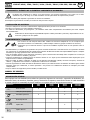
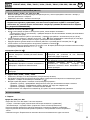
30 N.m
III
IV
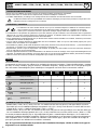
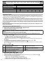
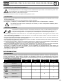
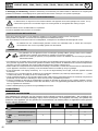
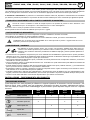
Niveau L 1 2 3 4 5 6 7 8 9 H
Tôle 0,3 mm 0,4 mm 0,5 mm 0,6 mm 0,7 mm 0,8 mm 0,9 mm 1 mm 1,1 mm 1,2 mm 1,3 mm
A
B
GYSPOT 34.02 & 34.04GYSPOT 2600 GYSPOT 2700
TOOLS
TOOLS
SELECT
TOOLS
DESIGN IN FRANCE
GYSPOT 39.02 / 39.04 / PRO 230 / PRO 400
10
10
2
GYSPOT 2600 / 2700 / 34.02 / 34.04 / 39.02 / 39.04 / PRO 230 / PRO 400

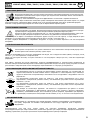
AVERTISSEMENTS - RÈGLES DE SÉCURITÉ
CONSIGNE GÉNÉRALE
Ces instructions doivent être lues et bien comprises avant toute opération.
Toute modication ou maintenance non indiquée dans le manuel ne doit pas être entreprise.
Tout dommage corporel ou matériel dû à une utilisation non-conforme aux inructions de ce manuel ne pourra être retenu à la
charge du fabricant.
En cas de problème ou d’incertitude, consulter une personne qualiée pour manier correctement l’inallation.
Ces inructions couvrent le matériel dans son état de livraison. Il e de la responsabilité de l’utilisateur de réaliser une analyse des
risques en cas de non-respect de ces inructions.
ENVIRONNEMENT
Ce matériel doit être utilisé uniquement pour faire des opérations de soudage dans les limites indiquées par la plaque signalétique
et/ou le manuel. Il faut respecter les directives relatives à la sécurité. En cas d’utilisation inadéquate ou dangereuse, le fabricant ne
pourra être tenu responsable.
L’inallation doit être utilisée dans un local sans poussière, ni acide, ni gaz inammable ou autres subances corrosives. Il en e
de même pour son ockage. S’assurer d’une circulation d’air lors de l’utilisation.
Plages de température :
Utilisation entre -10 et +40°C (+14 et +104°F).
Stockage entre -20 et +55°C (-4 et 131°F).
Humidité de l’air :
Inférieur ou égal à 50% à 40°C (104°F).
Inférieur ou égal à 90% à 20°C (68°F).
Altitude : Jusqu’à 1000 m au-dessus du niveau de la mer (3280 pieds).
PROTECTION INDIVIDUELLE ET DES AUTRES
Le soudage par résistance peut être dangereux et causer des blessures graves voire mortelles. Elle est destinée à être utilisée par du
personnel qualié ayant reçu une formation adaptée à l’utilisation de la machine (ex : formation carrossier).
Le soudage expose les individus à une source dangereuse de chaleur, d’étincelles, de champs électromagnétiques (attention au
porteur de pacemaker), de risque d’électrocution, de bruit et d’émanations gazeuses.
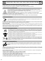
Pour bien se protéger et protéger les autres, respecter les instructions de sécurité suivantes :
An de se protéger de brûlures et rayonnements, porter des vêtements sans revers, isolants, secs, ignifugés et en
bon état, qui couvrent l’ensemble du corps.
Utiliser des gants qui garantissent l’isolation électrique et thermique.
Utiliser une protection de soudage et/ou une cagoule de soudage d’un niveau de protection susant (variable selon
les applications). Protéger les yeux lors des opérations de nettoyage. Les lentilles de contact sont particulièrement
proscrites.
Il est parfois nécessaire de délimiter les zones par des rideaux ignifugés pour protéger la zone des projections et des
déchets incandescents.
Informer les personnes dans la zone de soudage de porter les vêtements adéquats pour se protéger.
Utiliser un casque contre le bruit si le procédé de soudage atteint un niveau de bruit supérieur à la limite autorisée
(de même pour toute personne étant dans la zone de soudage).
Les pièces qui viennent d’être soudées sont chaudes et peuvent provoquer des brûlures lors de leur manipulation.
Lors d’intervention d’entretien sur la pince ou le pistolet, il faut s’assurer qu’il/elle soit susamment froid(e) en
attendant au moins 10 minutes avant toute intervention.
Il est important de sécuriser la zone de travail avant de la quitter an de protéger les personnes et les biens.
FUMÉES DE SOUDAGE ET GAZ
Les fumées, gaz et poussières émis par le soudage sont dangereux pour la santé. Il faut prévoir une ventilation
susante, un apport d’air est parfois nécessaire. Un masque à air frais peut être une solution en cas d’aération
insusante.
Vérier que l’aspiration est ecace en la contrôlant par rapport aux normes de sécurité.
Attention le soudage dans les environnements réduits nécessite une surveillance à diance de sécurité. Par ailleurs le soudage de
certains matériaux contenant du plomb, cadmium, zinc ou mercure voire du béryllium peuvent être particulièrement nocifs.
Dégraisser également les pièces avant de les souder. Le soudage doit être proscrit à proximité de graisse ou de peinture.
3
GYSPOT 2600 / 2700 / 34.02 / 34.04 / 39.02 / 39.04 / PRO 230 / PRO 400
FR
Notice originale

RISQUE DE FEU ET D’EXPLOSION
Protéger entièrement la zone de soudage, les matières inammables doivent être éloignées d’au moins 11 mètres.
Un équipement anti-feu doit être présent à proximité des opérations de soudage.
Attention aux projections de matières chaudes ou d’étincelles, car même à travers des ssures, elles peuvent être
source d’incendie ou d’explosion.
Éloigner les personnes, les objets inammables et les containers sous pressions à une diance de sécurité susante.
Le soudage dans des containers ou des tubes fermés e à proscrire et dans le cas où ils sont ouverts, il faut les vider de toute matière
inammable ou explosive (huile, carburant, résidus de gaz …).
Les opérations de meulage ne doivent pas être dirigées vers la source de courant de soudage ou vers des matières inammables.
SÉCURITÉ ÉLECTRIQUE
Le réseau électrique utilisé doit impérativement avoir une mise à la terre. Une décharge électrique peut être une
source d’accident grave direct ou indirect, voire mortel.
Ne jamais toucher les parties sous tension à l’intérieur comme à l’extérieur de la source de courant sous-tension (câbles, électrodes,
bras, piolet,…) car celles-ci sont branchées au circuit de soudage.
Avant d’ouvrir la source de courant de soudage, il faut la déconnecter du réseau et attendre 2 minutes. an que l’ensemble des
condensateurs soit déchargé.
Veiller à changer les câbles, électrodes ou bras, par des personnes qualiées et habilitées, si ceux-ci sont endommagés. Dimension-
ner la section des câbles en fonction de l’application. Toujours utiliser des vêtements secs et en bon état pour s’isoler du circuit de
soudage. Porter des chaussures isolantes, quel que soit le milieu de travail.
CLASSIFICATION CEM DU MATERIEL
Ce matériel de Classe A n’est pas prévu pour être utilisé dans un site résidentiel où le courant électrique est
fourni par le réseau public d’alimentation basse tension. Il peut y avoir des dicultés potentielles pour assurer la
compatibilité électromagnétique dans ces sites, à cause des perturbations conduites, aussi bien que rayonnées à
fréquence radioélectrique.
GYSPOT
2600 / 2700 / 34.04 /
39.04 / PRO 400
Ce matériel est conforme à la CEI 61000-3-11 si l’impédance du réseau au point de raccordement avec l’installation
électrique est inférieure à l’impédance maximale admissible du réseau Zmax = 0,77 Ohms.
GYSPOT
34.02 / 39.02 /
PRO 230
Ce matériel est conforme à la CEI 61000-3-11 si l’impédance du réseau au point de raccordement avec l’installation
électrique est inférieure à l’impédance maximale admissible du réseau Zmax = 0,84 Ohms.
Ce matériel n’est pas conforme à la CEI 61000-3-12 et est destiné à être raccordé à des réseaux basse tension
privés connectés au réseau public d’alimentation seulement au niveau moyenne et haute tension. S’il est connecté
à un réseau public d’alimentation basse tension, il est de la responsabilité de l’installateur ou de l’utilisateur du
matériel de s’assurer, en consultant l’opérateur du réseau de distribution, que le matériel peut être connecté.
EMISSIONS ELECTRO-MAGNETIQUES
Le courant électrique passant à travers n’importe quel conducteur produit des champs électriques et magnétiques
(EMF) localisés. Le courant de soudage produit un champ électromagnétique autour du circuit de soudage et du
matériel de soudage.
Les champs électromagnétiques EMF peuvent perturber certains implants médicaux, par exemple les imulateurs cardiaques. Des
mesures de protection doivent être prises pour les personnes portant des implants médicaux. Par exemple, rerictions d’accès pour
les passants ou une évaluation de risque individuelle pour les soudeurs.
Tous les soudeurs doivent utiliser les procédures suivantes an de minimiser l’exposition aux champs électromagnétiques provenant
du circuit de soudage:
• positionner les câbles de soudage ensemble – les xer avec une attache, si possible;
• se positionner (torse et tête) aussi loin que possible du circuit de soudage;
• ne jamais enrouler les câbles de soudage autour du corps;
• ne pas positionner le corps entre les câbles de soudage. Tenir les deux câbles de soudage sur le même côté du corps;
• raccorder le câble de retour à la pièce mise en œuvre aussi proche que possible à la zone à souder;
• ne pas travailler à côté de la source de courant de soudage, ne pas s’assoir dessus ou ne pas s’y adosser ;
• ne pas souder lors du transport de la source de courant de soudage ou le dévidoir.
Les porteurs de stimulateurs cardiaques doivent consulter un médecin avant d’utiliser ce matériel.
L’exposition aux champs électromagnétiques lors du soudage peut avoir d’autres eets sur la santé que l’on ne
connaît pas encore.
4
GYSPOT 2600 / 2700 / 34.02 / 34.04 / 39.02 / 39.04 / PRO 230 / PRO 400
FR
Notice originale

RECOMMANDATIONS POUR EVALUER LA ZONE ET L’INSTALLATION DE SOUDAGE
Généralités
L’utilisateur e responsable de l’inallation et de l’utilisation du matériel de soudage par résiance suivant les inructions du
fabricant. Si des perturbations électromagnétiques sont détectées, il doit être de la responsabilité de l’utilisateur du matériel de
soudage par résiance de résoudre la situation avec l’assiance technique du fabricant. Dans certains cas, cette action corrective
peut être aussi simple qu’une mise à la terre du circuit de soudage. Dans d’autres cas, il peut être nécessaire de conruire un écran
électromagnétique autour de la source de courant de soudage et de la pièce entière avec montage de ltres d’entrée. Dans tous les
cas, les perturbations électromagnétiques doivent être réduites jusqu’à ce qu’elles ne soient plus gênantes.
Evaluation de la zone de soudage
Avant d’inaller un matériel de soudage par résiance, l’utilisateur doit évaluer les problèmes électromagnétiques potentiels dans la
zone environnante. Ce qui suit doit être pris en compte:
a) la présence au-dessus, au-dessous et à côté du matériel de soudage par résiance d’autres câbles d’alimentation, de commande,
de signalisation et de téléphone;
b) des récepteurs et transmetteurs de radio et télévision;
c) des ordinateurs et autres matériels de commande;
d) du matériel critique de sécurité, par exemple, protection de matériel induriel;
e) la santé des personnes voisines, par exemple, emploi de imulateurs cardiaques ou d’appareils contre la surdité;
f) du matériel utilisé pour l’étalonnage ou la mesure;
g) l’immunité des autres matériels présents dans l’environnement.
L’utilisateur doit s’assurer que les autres matériels utilisés dans l’environnement sont compatibles. Cela peut exiger des mesures de
protection supplémentaires;
h) l’heure du jour où le soudage ou d’autres activités sont à exécuter.
La dimension de la zone environnante à prendre en compte dépend de la ructure du bâtiment et des autres activités qui s’y
déroulent. La zone environnante peut s’étendre au-delà des limites des inallations.
Evaluation de l’inallation de soudage
Outre l’évaluation de la zone, l’évaluation des inallations de soudage par résiance peut servir à déterminer et résoudre les cas de
perturbations. Il convient que l’évaluation des émissions comprenne des mesures in situ comme cela e spécié à l’Article 10 de la
CISPR 11. Les mesures in situ peuvent également permettre de conrmer l’ecacité des mesures d’atténuation.
RECOMMANDATIONS SUR LES METHODES DE REDUCTION DES EMISSIONS ELECTROMAGNETIQUES
a. Réseau public d’alimentation: Il convient de raccorder le matériel de soudage à l’arc au réseau public d’alimentation selon
les recommandations du fabricant. Si des interférences se produisent, il peut être nécessaire de prendre des mesures de prévention
supplémentaires telles que le ltrage du réseau public d’alimentation. Il convient d’envisager de blinder le câble d’alimentation dans
un conduit métallique ou équivalent d’un matériel de soudage à l’arc inallé à demeure. Il convient d’assurer la continuité électrique
du blindage sur toute sa longueur. Il convient de raccorder le blindage à la source de courant de soudage pour assurer un bon contact
électrique entre le conduit et l’enveloppe de la source de courant de soudage.
b. Maintenance du matériel de soudage par résiance : Il convient que le matériel de soudage par résiance soit soumis à
l’entretien de routine suivant les recommandations du fabricant. Il convient que tous les accès, portes de service et capots soient
fermés et correctement verrouillés lorsque le matériel de soudage à l’arc e en service. Il convient que le matériel de soudage à l’arc
ne soit modié en aucune façon, hormis les modications et réglages mentionnés dans les inructions du fabricant.
c. Câbles de soudage : Il convient que les câbles soient aussi courts que possible, placés l’un près de l’autre à proximité du sol ou
sur le sol.
d. Liaison équipotentielle : Il convient d’envisager la liaison de tous les objets métalliques de la zone environnante. Toutefois,
des objets métalliques reliés à la pièce à souder accroissent le risque pour l’opérateur de chocs électriques s’il touche à la fois ces
éléments métalliques et l’électrode. Il convient d’isoler l’opérateur de tels objets métalliques.
e. Mise à la terre de la pièce à souder : Lorsque la pièce à souder n’e pas reliée à la terre pour la sécurité électrique ou en
raison de ses dimensions et de son emplacement, ce qui e le cas, par exemple, des coques de navire ou des charpentes métalliques
de bâtiments, une connexion raccordant la pièce à la terre peut, dans certains cas, et non syématiquement, réduire les émissions.
Il convient de veiller à éviter la mise à la terre des pièces qui pourrait accroître les risques de blessure pour les utilisateurs ou
endommager d’autres matériels électriques. Si nécessaire, il convient que le raccordement de la pièce à souder à la terre soit
fait directement, mais dans certains pays n’autorisant pas cette connexion directe, il convient que la connexion soit faite avec un
condensateur approprié choisi en fonction des réglementations nationales.
f. Protection et blindage : La protection et le blindage sélectifs d’autres câbles et matériels dans la zone environnante peuvent
limiter les problèmes de perturbation. La protection de toute la zone de soudage peut être envisagée pour des applications spéciales.
TRANSPORT ET TRANSIT DE LA SOURCE DE COURANT DE SOUDAGE
La source de courant de soudage est équipée d’une (de) poignée(s) supérieure(s) permettant le portage / déplacement
à la main. Attention à ne pas sous-évaluer son poids. La (les) poignée(s) n’est (ne sont) pas considérée(s) comme un
moyen d’élingage.
Ne pas utiliser les câbles pour déplacer la source de courant de soudage.
Ne pas faire transiter la source de courant au-dessus de personnes ou d’objets.
5
GYSPOT 2600 / 2700 / 34.02 / 34.04 / 39.02 / 39.04 / PRO 230 / PRO 400
FR
Notice originale

6
GYSPOT 2600 / 2700 / 34.02 / 34.04 / 39.02 / 39.04 / PRO 230 / PRO 400
FR
Notice originale
INSTALLATION DU MATERIEL
• Prévoir une zone susante pour aérer la source de courant de soudage et accéder aux commandes.
• Ne pas utiliser dans un environnement comportant des poussières métalliques conductrices.
• Les câbles d’alimentation, de rallonge et de soudage doivent être totalement déroulés an d’éviter toute surchaue.
Le fabricant n’assume aucune responsabilité concernant les dommages provoqués à des personnes et objets dus à une
utilisation incorrecte et dangereuse de ce matériel.
ENTRETIEN / CONSEILS
• Les utilisateurs de cette machine doivent avoir reçu une formation adaptée à l’utilisation de la machine an de
tirer le maximum de ses performances et de réaliser des travaux conformes (ex : formation de carrossier).
• Vérier que le constructeur autorise le procédé de soudage employé avant toute réparation sur un véhicule.
• La maintenance et la réparation du générateur ne peut être eectuée que par le fabricant. Toute intervention dans ce générateur
eectuée par une tierce personne annulera les conditions de garantie. Le fabricant décline toute responsabilité concernant tout
incident ou accident survenant poérieurement à cette intervention.
• Couper l’alimentation en débranchant la prise, et attendre deux minutes avant de travailler sur le matériel. A l’intérieur, les tensions
et intensités sont élevées et dangereuses.
• Tous les outils de soudage subissent une détérioration lors de leur utilisation. Veiller à ce que ces outils reent propres pour que la
machine donne le maximum de ses possibilités.
• Avant d’utiliser le piolet, vérier l’état des diérents outils (étoile, électrode mono-point, électrode carbone, …) puis éventuellement
les nettoyer ou procéder à leur remplacement s’ils paraissent en mauvais état.
• Régulièrement, enlever le capot et dépoussiérer à la souette. En proter pour faire vérier la tenue des connexions électriques
avec un outil isolé par un personnel qualié.
• Contrôler régulièrement l’état du cordon d’alimentation et du faisceau du circuit de soudage. Si des signes d’endommagement sont
apparents, les remplacer par le fabricant, son service après-vente ou une personne de qualication similaire, an d’éviter tout danger.
• Laisser les ouïes de la source de courant de soudage libres pour l’entrée et la sortie d’air.
NOTICE
DESCRIPTION
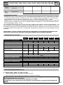
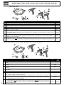
Ces appareils ont été conçus pour eectuer les opérations de carrosserie suivantes : Travaux de débosselage ; soudage
de clous, de rivets, rondelles, goujons moulures ; élimination d’impacts ; étirage de tôles. Ils ne sont pas prévu pour
faire des travaux d’assemblage de pièces métalliques. Ces appareils sont livrés avec les accessoires suivants :
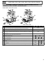
Accessoires 2600
2700
34.02
34.04
39.02
39.04
PRO 230
PRO 400
Plaque de masse
Câble piolet séparé
Automatic Quick Gun
Manual Quick Gun
Spotter Box
Spotter Box Pro
ALIMENTATION ÉLECTRIQUE
- GYSPOT 2600 / 2700 / 34.02 / 39.02 / Pro 230 : Ce matériel est livré avec une prise 16 A de type CEE7/7 et ne doit
être utilisé que sur une installation électrique monophasée 230 V (50 - 60 Hz) à trois ls avec un neutre relié à la terre.
((Zmax 39.02 / 34.02) = 0.84Ω) & (Zmax 2600 / 2700) = 0.77Ω))
- GYSPOT 34.04 / 39.04 / Pro 400 : Ce matériel est livré avec une prise 16 A de type CEE7/7 et ne doit être utilisé que
sur une installation électrique biphasée 400 V (50 - 60 Hz) à trois ls avec un neutre relié à la terre. (Zmax = 0.77Ω)
Le courant permanent absorbé (I1p ou ILp) indiqué dans la partie « caractéristiques électriques » de ce manuel cor-
respond aux conditions d’utilisation maximales. Vérier que l’alimentation et ses protections (fusible et/ou disjoncteur)
sont compatibles avec le courant nécessaire en utilisation. Dans certains pays, il peut être nécessaire de changer la
prise pour permettre une utilisation aux conditions maximales.
NB : Si l’appareil fait déclencher la protection de l’installation électrique, vérier le calibre et le type de
disjoncteur ou de fusibles utilisés.

7
GYSPOT 2600 / 2700 / 34.02 / 34.04 / 39.02 / 39.04 / PRO 230 / PRO 400
FR
Notice originale
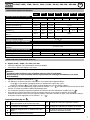
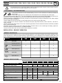
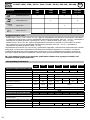
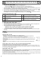
CARACTÉRISTIQUES TECHNIQUES
2600
2700
34.02 34.04 39.02 39.04 PRO 230 PRO 400
CARACTÉRISTIQUES ÉLECTRIQUES
Tension d’alimentation assignée U
1N
1 ~ 230 V 2 ~ 400 V 1 ~ 230 V 2 ~ 400 V 1 ~ 230 V 2 ~ 400 V
Fréquence
50/60 Hz
Tension à vide assignée U
20
5.5 V 7.6 V 7.8 V De 0.5 à 7.4 V
Puissance permanente Sp
1 kVA 1.8 kVA 2.0 kVA 1.8 kVA
Courant d’alimentation permanent I
1p
4.7 A 6.9 A 5.3 A 9 A 5 A 9 A 5 A
Courant maximal de court-circuit primaire
permanent I
1cc
43 A 80 A 51 A 90 A 52 A 90 A 52 A
Courant maximal de court-circuit secon-
daire I
2cc
1800 A 2400 A 2600 A 2800 A
Courant permanent secondaire I
2p
160 A 240 A 270 A 270 A
Type de courant de soudage
CARACTERISTIQUES THERMIQUES
Température ambiante de fonctionnement
De - 10°C à + 40°C
Température ambiante de stockage et de
transport
De -25°C à +55°C
CARACTERISTIQUES MECANIQUES
Dimensions (cm)
20x32x18 22.5x36 x23.5
Masse (kg)
17.8 21 22.7 23 25.5 25.5
Indice de protection
IP 21
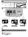
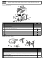
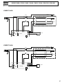
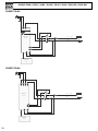
MISE EN ROUTE ET REGLAGE (FIG III)
A - Gyspot 39.02 / 39.04 / Pro 230 / Pro 400
• Connecter l’appareil à une alimentation électrique adaptée
• Connecter le pistolet à l’aide du connecteur.
Nb : Pro 230 et Pro 400 disposent en plus du connecteur de puissance d’un connecteur de commande
gâchette :
- Connecter cette dernière si vous souhaitez amorcer grâce à la gâchette.
- Déconnecter la, si vous souhaitez utiliser le générateur en amorçage automatique (voir partie
UTILISATION)
• Appuyer sur la touche « Marche/Arrêt » (
6
).
• Les acheurs et témoins lumineux s’allument un court instant puis l’appareil ache :
- L’outil
1
, n°1 par défaut (soudage d’étoiles ou utilisation de la pince tire-creux).
- Niveau de puissance
2
, n°5 par défaut (réglage adapté pour une tôle d’acier 0.8mm).
• Pour changer le niveau de puissance, appuyer sur les touches + ou –
3
. En maintenant enfoncé une de ces deux
touches, le niveau de puissance délera automatiquement.
• Les niveaux de puissance proposés permettent de redresser des tôles d’épaisseur variables (g. IV-
A
).
• Pour changer le type d’outil utilisé en bout de pistolet, appuyer sur la touche de sélection de l’outil
4
.
L’acheur de numéro d’outil se met à clignoter pendant 5 secondes. Pendant ce délai, il est possible de changer
de numéro d’outil en appuyant sur les touches + ou - (
3
).
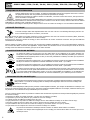
Outils disponibles (g. IV-
B
)
1
Travaux de débosselage à l’aide du marteau à
inertie, des étoiles ou de la pince tire-creux.
5 Soudage de rivets pour baguettes latérales
2
Soudage de l ondulé ou d’anneaux pour
des travaux de redressage.
6 Soudage de rondelles pour xation de la masse.
3
Rabattage d’impacts avec un embout cuivre spé-
cique.
7
Soudage de goujons pour xation des masses
véhicules et faisceaux de liaison
4
Electrode au carbone pour retente.

8
GYSPOT 2600 / 2700 / 34.02 / 34.04 / 39.02 / 39.04 / PRO 230 / PRO 400
FR
Notice originale
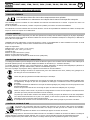
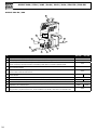
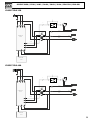
B - Gyspot 2600 / 2700 / 34.02 / 34.04
• Connecter l’appareil à une alimentation électrique adaptée,
• La mise en marche du GYSPOT 2600/ 2700 / 34.02 / 34.04 s’eectue par rotation du potentiomètre (la mise en
veille se fait sur la position «O» du potentiomètre). (
6
)
• Sélectionner le mode d’utilisation à l’aide du potentiomètre de réglage :
- Plage 7 (gauche) : Soudage d’étoiles ou d’anneaux pour des opérations de tirage de tôles.
- Plage 8 (haut) : Soudage de l ondulé, idéal pour les zones arrondies
- Plage 9 (droite) : Rabattage d’impacts avec l’embout cuivre adapté
• Pour changer le niveau de puissance, tourner le potentiomètre jusqu’à la puissance désirée dans la plage choisie..
UTILISATION
1- Amorçage
Gyspot Pro 230 / Pro 400
Le Gyspot Pro 230 et Pro 400 disposent de 2 systèmes d’amorçage :
En mode manuel, connecter le connecteur de puissance et le connecteur de commande de la gâchette.
En mode manuel, le mode automatique ne fonctionne plus, seule une pression sur la gâchette permet
le point de soudage. Le commutateur permet d’activer ou de désactiver la gâchette du pistolet.
GYSPOT 2600 / 39.02 / 39.04 / Pro 230 / Pro 400 avec gâchette déconnectée
L’appareil est muni d’un système d’amorçage automatique du point de soudage.
Le générateur va automatiquement détecter le contact électrique et générer un point de soudage dans un délai
inférieur à 1 seconde. Pour générer un 2ème point, il faut rompre le contact en bout de pistolet pendant au moins ½
seconde puis établir un nouveau contact.
Gyspot 2700 / 34.02 / 34.04
Ce générateur est équipé d’un pistolet à gâchette pour des opérations manuelles. Un commutateur permet d’activer la
fonction « crayon graphite » (bouton 10).
Le potentiomètre possède 2 plages d’utilisations en fonctions de la position du bouton 10. Une plage pour le crayon
graphite et une plage pour les autres outils.
A l’allumage de l’appareil, un clignotement toutes les ½ secondes de la LED jaune « STOP » indique que la gâchette
du pistolet est restée enfoncée, ou que le câble pistolet est défectueux.
2- Fonctionnement
Procéder comme suit :
• Connecter la plaque de masse du générateur à la pièce de tôlerie à redresser en suivant les conseils suivants:
- la placer au point le plus proche de l’endroit où vous devez travailler.
- ne pas la connecter sur une pièce voisine
(Exemple: ne pas connecter la masse sur une portière pour redresser l’aile du véhicule)
- décaper proprement la tôle à l’endroit de la connexion
• Décaper l’endroit où doit être travaillée la tôle.
• Placer au bout du pistolet un des outils fournis.
• Sélectionner l’outil et de la puissance (cf partie mise en marche et réglage)
• Mettre en contact l’outil du pistolet avec la tôle à souder.
• Réaliser votre point de soudure.
Pour un fonctionnement optimal, il est préconisé d’utiliser le câble de masse et les pistolets
livrés d’origine.
PROTECTION THERMIQUE DU GENERATEUR
L’appareil est muni d’un système de protection thermique automatique. Ce système bloque l’utilisation du générateur
pendant quelques minutes en cas d’utilisation trop intensive. Dans ce cas, le témoin jaune (g. III-
5
) de défaut
thermique s’allume.

9
GYSPOT 2600 / 2700 / 34.02 / 34.04 / 39.02 / 39.04 / PRO 230 / PRO 400
FR
Notice originale
GARANTIE
La garantie couvre tous défauts ou vices de fabrication pendant 2 ans, à compter de la date d’achat (pièces et main
d’oeuvre).
La garantie ne couvre pas :
• Toutes autres avaries dues au transport.
• L’usure normale des pièces (Ex. : câbles, pinces, etc.).
• Les incidents dus à un mauvais usage (erreur d’alimentation, chute, démontage).
• Les pannes liées à l’environnement (pollution, rouille, poussière).
En cas de panne, retourner l’appareil à votre distributeur, en y joignant :
- un justicatif d’achat daté (ticket de sortie de caisse, facture….)
- une note explicative de la panne.

STANDARD
GENERAL INSTRUCTIONS
Read and understand the following safety instructions before use.
Any modication or maintenance not specied in the instructions manual should not be undertaken.
The manufacturer is not liable for any injury or damage due to non-compliance with the inructions featured in this manual.
In the event of problems or uncertainties, please consult a qualied person to handle the inallation properly.
Make sure to keep the inructions as you might need to refer to them later.
These inructions cover the material in the condition it was delivered. It is the responsibility of the user to carry a risk analysis in
case the inructions are not followed.
ENVIRONMENT
This equipment mu only be used for welding operations in accordance with the limits indicated on the descriptive panel and/or in
the user manual. Safety inructions mu be followed. In case of improper or unsafe use, the manufacturer cannot be held liable.
This equipment mu be used and ored in a room free from du, acid, ammable gas or any other corrosive agent. The same
rules apply for orage. Operate the machine in an open, or well-ventilated area.
Operating temperature:
Use between -10 and +40°C (+14 and +104°F).
Storage between -20 and +55°C (-4 and 131°F).
Air humidity:
Lower or equal to 50% at 40°C (104°F).
Lower or equal to 90% at 20°C (68°F).
Altitude:
Up to 1000 meters above sea level (3280 feet).
PROTECTION OF THE INDIVIDUALS
Resistance welding can be dangerous and cause serious injuries or even death. It needs to be used by a qualied technician with
training relevant to the machine.
Welding exposes the user to dangerous heat, arc rays, electromagnetic elds, risk of electric shock, noise and gas fumes. People
wearing pacemakers are advised to consult a doctor before using the welding machine.
To protect oneself as well as the other, ensure the following safety precautions are taken:
In order to protect you from burns and radiations, wear clothing without turn-up or cus. These clothes must be
insulating, dry, reproof, in good condition and cover the whole body.
Wear protective gloves which guarantee electrical and thermal insulation.
Use sucient welding protective gear for the whole body: hood, gloves, jacket, trousers... (varies depending on the
application/operation). Protect the eyes during cleaning operations. Contact lenses are prohibited during use.
It may be necessary to install reproof welding curtains to protect others against arc rays, weld spatters and sparks. .
Ask people around the working area to look away from at the arc or the molten metal, and to wear protective clothing.
Ensure ear protection is worn by the operator if the work exceeds the authorised noise limit (the same applies to any
person in the welding area).
Parts that have previously been welded will be hot and may cause burns if manipulated. During maintenance work
on the torch or the electrode holder, you should make sure it’s cold enough and wait at least 10 minutes before any
intervention. When using a water-cooled torch, make sure that the cooling unit is switched on to avoid any burns
caused by the liquid.
It is important to secure the working area before leaving to ensure the protection of property and the safety of others.
WELDING FUMES AND GAS
Fumes, gas and dust produced during welding are hazardous to health. It is mandatory to ensure adequate
ventilation and/or extraction to keep fumes and gas away from the work area. Using an air fed welding helmet is
recommended in case of insucient ventilation in the workplace.
Check that the air supply is eective by referring to the recommended safety regulations.
10
GYSPOT 2600 / 2700 / 34.02 / 34.04 / 39.02 / 39.04 / PRO 230 / PRO 400
EN
Translation of the original instructions

Precautions mu be taken when welding in small areas, and the operator will need supervision from a safe diance. In addition, the
welding of certain materials containing lead, cadmium, zinc, mercury or beryllium may be particularly harmful.
Also remove any grease on the metal pieces before welding. Do not weld in areas where grease or paint are ored.
FIRE AND EXPLOSION RISKS
Protect the entire welding area. Flammable materials must be moved to a minimum safe distance of 11 meters.
A re extinguisher must be readily available near the welding operations.
Keep people, ammable materials/objects and containers that are under pressure at a safe diance.
Welding in closed containers or pipes should be avoided and , if they are opened, they mu be emptied of any ammable or explosive
material (oil, fuel, gas ...).
Grinding operations should not be carried out close to the power supply or any ammable materials.
ELECTRICAL SAFETY
The electrical mains used must have an earth terminal. An electric shock could cause serious injuries or potentially
even deadly accidents.
Never make contact with live parts inside or outside the current source (cables, electrodes, arms, guns...) as they are connected to
the welding circuit.
Before opening the device, it is imperative to disconnect it from the mains and wait 2 minutes, so that all the capacitors are discharged.
Damaged cables and torches mu be changed by a qualied and skilled professional. Make sure that the cable cross section is ade-
quate with the usage (extensions and welding cables). Always wear dry clothes which are in good condition in order to be isolated
from the welding circuit. Wear insulating shoes, regardless of the workplace/environment in which you work in.
EMC CLASSIFICATION
This Class A machine is not intended to be used on a residential site where the electric current is supplied by the
domestic low-voltage power grid. There may be potential diculties in ensuring electromagnetic compatibility at
these sites, due to conducted interferences as well as radiation.
GYSPOT
2600 / 2700 / 34.04 /
39.04 / PRO 400
This equipment complies with IEC 61000-3-11 if the power supply network’s impedance at the electrical
installation’s connection point is inferior to the network’s maximum admissible impendance Zmax = 0,77 Ohms.
GYSPOT
34.02 / 39.02 /
PRO 230
This equipment complies with IEC 61000-3-11 if the power supply network’s impedance at the electrical
installation’s connection point is inferior to the network’s maximum admissible impendance Zmax = 0,84 Ohms.
This equipment does not comply with IEC 61000-3-12 and is intended to be connected to domestic low-voltage
systems interfacing with the public supply only at the medium- or high-voltage level. If it is connected to a public
low-voltage power grid, the installer or user of the machine has to ensure, by checking with the network operator,
that the device can be connected.
ELECTROMAGNETIC INTERFERENCES
The electric currents owing through a conductor cause electrical and magnetic elds (EMF). The welding current
generates an EMF around the welding circuit and the welding equipment.
The EMF electromagnetic elds can interfere with certain medical implants, such as pacemakers. Protection measures mu be taken
for people having medical implants. For example, access rerictions for passers-by or an individual risk evaluation for the welders.
Each welder mu follow the procedures below in order to minimise exposure to electromagnetic generated by the welding circuit:
• position the welding cables together - rap them if possible;
• keep your head and top half of the body as far from the welding circuit as possible;
• never enrol the cables around your body;
• never position your body between the welding cables. Hold both welding cables on the same side of your body;
• connect the earth clamp as close as possible to the area being welded;
• do not work too close to, do not lean and do not sit on the welding machine
• do not weld when you’re carrying the welding machine or its wire feeder.
People wearing pacemakers are advised to consult their doctor before using this device.
Exposure to electromagnetic elds while welding may have other health eects which are not yet identied.
RECOMMENDATIONS FOR EVALUATING THE WELDING AREA AND INSTALLATION
Miscellaneous
The user is responsible for the correct inallation and usage of the welding material based on the inructions supplied by the
manufacturer. If electromagnetic diurbances are detected, it is the user’s responsibility to resolve the situation with the manufacturer’s
11
GYSPOT 2600 / 2700 / 34.02 / 34.04 / 39.02 / 39.04 / PRO 230 / PRO 400
EN
Translation of the original instructions

technical assiance. In some cases, this corrective action may be as simple as earthing the welding circuit. In other cases, it may be
necessary to conruct an electromagnetic shield around the welding power source and around the entire piece by tting input lters.
In all cases, electromagnetic interferences mu be reduced until they are no longer inconvenient.
Welding area assessment
Before inalling the machine, the user mu evaluate the possible electromagnetic problems that may arise in the area where the
inallation is planned. The following mu be taken into account:
a) the presence (above, below and next to the arc welding machine) of other power cables, remote cables and telephone cables;
b) television transmitters and receivers;
c) computers and other hardware;
d) critical safety equipment such as indurial machine protections;
e) the health and safety of the people in the area such as people with pacemakers or hearing aids;
f) calibration and measuring equipment;
g) the isolation of other pieces of equipment which are in the same area.
The user has to ensure that the devices and pieces of equipment used in the same area are compatible with each other. This may
require extra precautions;
h) the time of day during the welding or other activities have to be performed.
The surface of the area to be considered around the device depends on the building’s ructure and other activities that take place
there. The area taken into consideration can be larger than the limits of the inallations.
Review of the welding inallation
Reviewing the welding inallations can be useful to determine and resolve any case of electrical diurbances. The assessment of
emissions mu include in situ measurements as specied in Article 10 of CISPR 11. In situ measurements can also be used to conrm
the eectiveness of mitigation measures.
RECOMMANDATIONS SUR LES METHODES DE REDUCTION DES EMISSIONS ELECTROMAGNETIQUES
a. National power grid: The arc welding machine mu be connected to the national power grid in accordance with the manufacturer’s
recommendation. In case of interferences, it may be necessary to take additional precautions such as the ltering of the power supply
network. Consideration should be given to shielding the power supply cable in a metal conduit or equivalent of permanently inalled
arc welding equipment. It is necessary to ensure the electrical continuity of the shielding along its entire length. The shielding should
be connected to the welding current’s source to ensure good electrical contact between the conduct and the casing of the welding
current source.
b. Maintenance of the arc welding equipment: The arc welding machine should be subject to a routine maintenance check
according to the recommendations of the manufacturer. All accesses, service doors and covers should be closed and properly locked
when the arc welding equipment is on. The arc welding equipment mu not be modied in any way, except for the changes and
settings outlined in the manufacturer’s inructions.
c. Welding cables: Cables mu be as short as possible, close to each other and close to the ground, if not on the ground.
d. Equipotential bonding: consideration should be given to bonding all metal objects in the surrounding area. However, metal
objects connected to the workpiece increase the risk of electric shock if the operator touches both these metal elements and the
electrode. It is necessary to insulate the operator from such metal objects.
e. Earthing of the welded part: When the part is not earthed - due to electrical safety reasons or because of its size and its
location (which is the case with ship hulls or metallic building ructures), the earthing of the part can, in some cases but not
syematically, reduce emissions It is preferable to avoid the earthing of parts that could increase the risk of injury to the users or
damage other electrical equipment. If necessary, it is appropriate that the earthing of the part is done directly, but in some countries
that do not allow such a direct connection, it is appropriate that the connection is made with a capacitor selected according to national
regulations.
f. Protection and shielding: The selective protection and shielding of other cables and devices in the area can reduce perturbation
issues. The protection of the entire welding area can be considered for specic situations.
TRANSPORT ET TRANSIT DE LA SOURCE DE COURANT DE SOUDAGE
The welding source is tted with a handle to make it transportable by hand. Be careful not to underestimate the weight
of the machine. The handle are not design to be use to hang the machine to something else.
Do not use the cables or torch to move the machine.
Do not place/carry the unit over people or objects.
EQUIPMENT INSTALLATION
• Provide an adequate area to ventilate the machine and access the controls.
• Do not use in an area with conductive metal du.
• Power cables, extension leads and welding cables mu be fully uncoiled to prevent overheating.
12
GYSPOT 2600 / 2700 / 34.02 / 34.04 / 39.02 / 39.04 / PRO 230 / PRO 400
EN
Translation of the original instructions

The manufacturer does not accept any liability in relation to damages caused to objects or harm caused to persons
as the result of incorrect and/or dangerous use of the machine .
MAINTENANCE / RECOMMENDATIONS
• The operators must have received suitable training in order to use the machine at its maximum potential and
weld correctly.
• Check which welding process is authorised by the manufacturer before attempting any vehicle repair.
• The maintenance and the repair of the . Any work undertaken by a third party on the generator will invalidate the warranty. The
manufacturer will not accept liability in the event of an incident that would occur after this work was undertaken.
• Ensure the machine is unplugged from the mains, and wait for two minutes before carrying out maintenance work. Inside, voltages
and currents are high and dangerous.
• All the welding tools will wear o with use. Ensure that these tools are clean to get the be results.
• Prior to using the gun, check the condition of the dierent tools (ar, single sided electrode, carbon electrode...) and clean or
replace if required.
• Remove regularly the casing and any excess of dust. Take this opportunity to have the electrical connections checked by a qualied
person, with an insulated tool.
• Regularly review the condition of the power cable and welding connection cables. In case of visible signs of damage, organise for
them to be replaced by the manufacturer or a qualied technician.
• Ensure the vents of the device are not blocked to allow adequate air circulation.
INSTALLATION – PRODUCT OPERATION
GENERAL DESCRIPTION
This product has been designed to carry out the following operations in a car body workshop: Dent pulling; welding of nails,
rivets, rings and pins; removal of bumps and dents; sheet stretching. It is not designed for the assembly of metal parts. This
device is delivered with an earth clamp, a gun (with cable), a consumables and accessories box, and an SOOW mains cable.
Accessories 2600
2700
34.02
34.04
39.02
39.04
PRO 230
PRO 400
Earth plate
Separate gun lead
Automatic Quick Gun
Manual Quick Gun
Spotter Box
Spotter Box Pro
PRODUCT SPECIFICATIONS
2600
2700
34.02 34.04 39.02 39.04 PRO 230 PRO 400
ELECTRIC SPECIFICATIONS
U
1N
rated power supply voltage
1 ~ 230 V 2 ~ 400 V 1 ~ 230 V 2 ~ 400 V 1 ~ 230 V 2 ~ 400 V
Frequency
50/60 Hz
U
20
rated no load voltage
5.5 V 7.6 V 7.8 V De 0.5 à 7.4 V
Permanent power U
SP
1 kVA 1.8 kVA 2.0 kVA 1.8 kVA
Permanent supply current I
1p
4.7 A 6.9 A 5.3 A 9 A 5 A 9 A 5 A
Maximal current of a permanent primary
short circuit I
1cc
43 A 80 A 51 A 90 A 52 A 90 A 52 A
Maximal current of a secondary short cir-
cuit I
2cc
1800 A 2400 A 2600 A 2800 A
Permanent secondary current I
2p
160 A 240 A 270 A 270 A
Type of welding current
13
GYSPOT 2600 / 2700 / 34.02 / 34.04 / 39.02 / 39.04 / PRO 230 / PRO 400
EN
Translation of the original instructions

THERMAL SPECIFICATIONS
Operating ambient temperature
De - 10°C à + 40°C
Storage and transport operating ambient
De -25°C à +55°C
MECANICAL SPECIFICATIONS
Dimensions (cm)
20x32x18 22.5x36 x23.5
Weight (kg)
17.8 21 22.7 23 25.5 25.5
Protection rating
IP 21
ELECTRICITY SUPPLY
- GYSPOT 2600 / 2700 / 34.02 / 39.02 / Pro 230 : The material is supplied with a 16A plug type CEE7/7 and must
only be used on a single-phase electrical installation 230V (50-60 Hz) with 3 wires including one connected to earth.
((Zmax 39.02 / 34.02) = 0.84Ω) & (Zmax 2600 / 2700) = 0.77Ω))
- GYSPOT 34.04 / 39.04 / Pro 400 : The material is supplied with a 16A plug type CEE7/7 and must only be used on a
two-phase electrical installation 400 V (50-60 Hz) with 3 wires including one connected to earth. (Zmax = 0.77Ω)
The permanent current absorbed (l1p or ILp) displayed in the section «technical specications» of this manual relates
to use at maximum power. Check that the power supply and its protection (fuse and/or circuit breaker) are compatible
with the current needed by the machine. In some countries, it may be necessary to change the plug to allow the use
at maximum settings.
NB: If the product trips the circuit breaker, please check that the correct fuse and an adequate circuit
breaker are being used.
OPERATING AND SETTING (FIG III-PAGE 2)
A - Gyspot 39.02 / Gyspot 39.04 / Gyspot Pro 230 / Gyspot Pro 400
• Connect the machine to an approprate power supply
• Connect the gun with its connector.
Nb: Pro 230 and Pro 400 have, in addition to the power connector, a connector to command the torch
trigger:
- Connect the latter if you wish to start by using the trigger.
- Disconnect it if you prefer using the generator with automatic start (see OPERATION section).
• Press the « on/o » key (
6
).
• The indicators switch on for few seconds then the machine displays:
- Tool
1
, n°1 by default, (star welding or dent pulling clamp).
-
2
, Power level, n°5 by default, (setting adapted for 0.8mm steel sheets).
• To change the power level, press the + or – keys
3
. Keep the desired key pressed to scroll through the levels
automatically.
• The available power levels allow the straightening of sheets of varying thickness (g IV-
A
).
• To change the tool used with the gun, press the tool selection key
4
.
The tool indicator will blink for 5 seconds. During this time, it is possible to change the tool number by pressing
the + or - keys (
3
).
Available Tools (g. IV-
B
)
1
Straightening using the star hammer,
or dent pulling clamp.
5 Welding rivets for side rods
2 Crimped welding wire or rings for straightening 6 Welding rings for xing vehicle body.
3 Impact reduction with specic copper tip 7
Welding studs for vehicle body and connecting
beams
4 Carbon electrode for tempering
B - Gyspot 2600 / 2700 / 34.02 / 34.04
• Connect the machine to an appropriate power supply,
• To start the equipment, turn on the potentiometer. Put the potentiometer on «O» for standby mode (
6
).
• Select the start mode using the potentiometer:
- Range 6 (left): star or ring welding for sheet stretching.
- Range 7 (top): corrugated wire welding, ideal for curved areas.
- Range 8 (right): Dent pulling work with the adapted copper tip.
• To change the power level, rotate the potentiometer up to the required power.
14
GYSPOT 2600 / 2700 / 34.02 / 34.04 / 39.02 / 39.04 / PRO 230 / PRO 400
EN
Translation of the original instructions

15
GYSPOT 2600 / 2700 / 34.02 / 34.04 / 39.02 / 39.04 / PRO 230 / PRO 400
EN
Translation of the original instructions
OPERATING
1- Start-up
Gyspot Pro 230 / Pro 400
The Gyspot Pro 230 and Pro 400 have 2 settings:
Manual, by using the trigger (Plug the power and command connectors)
On manual mode, connect the power and trigger command connectors.
Automatic mode is disabled, only pressure on the trigger will create the arc. The switch enables to
activate or deactivate the trigger gun.
GYSPOT 2600 / 39.02 / 39.04 / Pro 230 / Pro 400 - AUTOMATIC
The machine is able to create the welding arc automatically. The generator will automatically detect the electrical
contact and create the welding arc in less than 1 second. To create a new arc, stop the contact with the gun tip for at
least ½ second and establish contact again to form another arc.
Gyspot 2700 / 34.02 / 34.04
This generator is equipped with a trigger operated gun for manual operation. A switch enables the activation of the
function « graphite pencil » (knob 10).
The potentiometer has 2 ranges of application according to the position of knob 10. One for the graphite pencil and
the second for the other tools.
When starting the device, if the yellow light ashes « STOP » (every half second), this indicates either the gun trigger
is depressed or there is a fault in the gun cable.
2- How to operate:
Follow the process:
• Connect the earth clamp of the generator to the sheet metal to be straightened and follow the instructions below:
- Connect it as close as possible to the place to be welded.
- DO NOT connect it to a dierent part of the car body.
(Example: Do not connect it on the door when working on the wing)
- Ensure the metal has been properly stripped at the connection point.
• Strip the area where the metal is to be worked.
• Attach the required tool to the end of the gun.
• Select the tool and the power level (see “Operating and Setting”) on the machine
• Make contact between the tool on the gun and the metal.
• Generate your welding arc.
Caution: For optimum operation, it is recommended to use the delivered earth cable and gun
originally supplied.
THERMAL PROTECTION
The machine is provided with an automatic thermal protection system, which will stop the machine to prevent it from
overheating. When the Thermal Protection Indicator illuminates, leave the machine to cool down.
WARRANTY
The warranty covers faulty workmanship for 2 years from the date of purchase (parts and labour).
The warranty does not cover:
• Transit damage.
• Normal wear of parts (eg. : cables, clamps, etc..).
• Damages due to misuse (power supply error, dropping of equipment, disassembling).
• Environment related failures (pollution, rust, dust).
In case of failure, return the unit to your distributor together with:
- The proof of purchase (receipt etc ...)
- A description of the fault reported

16
GYSPOT 2600 / 2700 / 34.02 / 34.04 / 39.02 / 39.04 / PRO 230 / PRO 400
DE
Übersetzung der Originalbetriebsanleitung
NORM
ALLGEMEIN
Die Missachtung dieser Anweisungen und Hinweise kann zu schweren Personen- und Sachschäden
führen.
Nehmen Sie keine Wartungarbeiten oder Veränderungen am Gerät vor, die nicht in der Anleitung
gennant werden.
Der Hereller haftet nicht für Verletzungen oder Schäden, die durch unsachgemäße Handhabung dieses Gerätes entanden sind.
Bei Problemen oder Fragen zum korrekten Gebrauch dieses Gerätes, wenden Sie sich bitte an entsprechend qualiziertes und
geschultes Fachpersonal.
Bewahren Sie diese Bedienungsanleitung zum späteren Nachschlagen auf
Diese Anweisungen beziehen sich auf das Material im Auslieferungszuand. Es liegt in der Verantwortung des Benutzers, bei Nichtein-
haltung dieser Anweisungen eine Risikoanalyse durchzuführen
UMGEBUNG
Dieses Gerät darf ausschließlich für Schweißarbeiten für die auf dem Siebdruck-Aufdruck bzw. dieser Anleitung angegebenen
Materialanforderungen (Material, Materialärke, usw) verwendet werden. Beachten Sie die Sicherheitsanweisungen. Der Hereller
i nicht für Schäden bei falscher oder gefährlichen Verwendung verantwortlich.
Verwenden Sie das Gerät nicht in Räumen, in denen sich in der Luft größere Mengen metallischer Staubpartikel benden, die
Elektrizität leiten können. Achten Sie sowohl beim Betrieb als auch bei der Lagerung des Gerätes auf eine Umgebung, die frei von
Säuren, Gasen und anderen ätzenden Subanzen i. Achten Sie auf eine gute Belüftung und ausreichenden Schutz bzw. Ausattung
der Räumlichkeiten.
Betriebemperatur:
zwischen -10 und +40°C (+14 und +104°F).
Lagertemperatur zwischen -20 und +55°C (-4 und 131°F).
Luftfeuchtigkeit:
Niedriger oder gleich 50% bis 40°C (104°F).
Niedriger oder gleich 90% bis 20°C (68°F).
Das Gerät i bis in einer Höhe von 1000m (über NN) einsetzbar.
SICHERHEITSHINWEISE
Widerstandsschweißen kann gefährlich sein und zu schweren - unter Umständen auch tödlichen - Verletzungen führen. Das Gerät
ist für den Gebrauch durch qualiziertes Personal geeignet, das eine an den Gebrauch der Maschine angepasste Ausbildung erhalten
hat (z.B. Karosserie-Ausbildung).
Beim Widerstandsschweißen ist der Anwender einer Vielzahl potentieller Risiken ausgesetzt: gefährlicher Hitze, elektromagnetische
Störungen (Personen mit Herzschnittmacher oder Hörgerät sollten sich vor Arbeiten in der Nähe der Maschinen von einem Arzt
beraten lassen), elektrische Schläge, Schweißlärm und -rauch.
Schützen Sie daher sich selbst und andere. Beachten Sie unbedingt die folgenden Sicherheitshinweise:
Die Strahlung des Lichtbogens kann zu schweren Augenschäden und Hautverbrennungen führen. Die Haut muss
durch geeignete trockene Schutzbekleidung (Schweißerhandschuhe, Lederschürze, Sicherheitsschuhe) geschützt
werden.
Tragen Sie elektrisch- und wärmeisolierende Handschuhe.
Tragen Sie bitte Schweißschutzkleidung und einen Schweißschutzhelm mit einer genügen Schutzstufe (je nach
Schweißart und -strom). Schützen Sie Ihre Augen bei Reinigungsarbeiten. Kontaktlinsen sind ausdrücklich verboten!
Schirmen Sie den Schweißbereich bei enstprechenden Umgebungsbedingungen durch Schweißvorhänge ab, um
Dritte vor Schweißspritzen, usw. zu schützen.
In der Nähe des Lichtbogens bendliche Personenn müssen ebenfalls auf Gefahren hingewiesen werden und mit den
nötigen Schutzmitteln ausgerüstet werden.
Bei Gebrauch des Schweißgerätes ensteht sehr großer Lärm, der auf Dauer das Gehör schädigt. Tragen Sie daher im
Dauereinsatz ausreichend Gehörschutz und schützen Sie in der Nähe arbeitende Personen.
ACHTUNG! Das Werkstück ist nach dem Schweißen sehr heiß! Seien Sie daher im Umgang mit dem Werkstück
vorsichtig, um Verbrennungen zu vermeiden. Achten Sie vor Instandhaltung / Reinigung der wassergekühlten
Zange oder der Pistole darauf, dass Kühlaggregat nach Schweißende ca. 10 min weiterlaufen zu lassen, damit die
Kühlüssigkeit entsprechend abkühlt und Verbrennungen vermieden werden.
Der Arbeitsbereich muss zum Schutz von Personen und Geräten vor dem Verlassen gesichert werden.

17
GYSPOT 2600 / 2700 / 34.02 / 34.04 / 39.02 / 39.04 / PRO 230 / PRO 400
DE
Übersetzung der Originalbetriebsanleitung
SCHWEISSRAUCH/-GAS
Beim Schweißen entstehen Rauchgase bzw. toxische Dämpfen. Sorgen Sie daher immer für ausreichende
Frischluftzufuhr, technische Belüftung oder ein zugelassenes Atemgerät.
Schweißen Sie nur in gut belüfteten Hallen, im Freien oder in geschlossenen Räumen mit ausreichend starker
Absaugung, die den aktuellen Sicherheitsstandards entspricht.
Achtung! Bei Schweißarbeiten in kleinen Räumen müssen Sicherheitsabände besonders beachtet werden. Beim Schweißen von Blei,
auch in form von Überzügen, verzinkten Teilen, Kadmium, «kadmierte Schrauben», Beryllium (mei als Legierungsbeandteil, z.B.
Beryllium-Kupfer) und andere Metalle entehen giftige Dämpfe.
Vor dem Schweißen, entfetten Sie die Werkücke. Schweißarbeiten in unmittelbarer Nähe von Fett und Farben sind grundsätzlich
verboten!
BRAND- UND EXPLOSIONSGEFAHR
Sorgen Sie für ausreichenden Schutz des Schweißbereiches. Der Sicherheitsaband für Gasaschen (brennbare
Gase) und andere brennbare Materialien beträgt mindeens 11 Meter.
Brandschutzausrüung muss im Schweißbereich vorhanden sein.Beachten Sie, dass die beim Schweißen
entehende heiße Schlacke, Spritzer und Funken eine potentielle Quelle für Feuer oder Explosionen darellen.
Behalten Sie einen Sicherheitsaband zu Personen, entammbaren Gegenänden und Druckbehältern.
Schweißen Sie keine Behälter mit brennbare Materialien (auch keine Ree davon) -> Gefahr entammbarer Gase. Falls sie geönet
sind, müssen entammbares oder explosive Material entfernt werden.
Arbeiten Sie bei Schleifarbeiten immer in entgegengesetzer Richtung zu diesem Gerät und entammbaren Materialen.
ELEKTRISCHE SICHERHEIT
Das Schweißgerät darf nur an einer geerdeten Netzversorgung betrieben werden. Das Berühren stromführender
Teile kann tödliche elektrische Schläge, schwere Verbrennungen bis zum Tod verursachen.
Berühren Sie daher UNTER KEINEN UMSTÄNDEN Teile des Geräteinneren oder das geönete Gehäuse wenn das Gerät mit dem
Stromnetz verbunden i..
Trennen Sie IMMER das Gerät vom Stromnetz und warten Sie 2 weitere Minuten BEVOR Sie das Gerät önen, damit sich die Span-
nung der Kondensatoren entladen kann.
Ausschließlich qualiziertem und geschultem Fachpersonal i es vorbehalten beschädigte Kabel, Elektroden und Zangen auszu-
tauschen. Achten Sie beim Auausch ets darauf das entsprechende Äquivalent zu verwenden. Tragen Sie zur Isolierung beim
Schweißen immer trockene Kleidung in gutem Zuand. Achten Sie unabhängig der Umgebungsbedingungen ets auf isolierendes
Schuhwerk.
CEM-KLASSE DES GERÄTES
Der Norm IEC 60974-10 entsprechend, wird dieses Gerät als Klasse A Gerät eingestuft und ist somit für den
industriellen und/oder professionellen Gebrauch geeignet. Es ist nicht für den Einsatz in Wohngebieten bestimmt,
in denen die lokale Stromversorgung über das öentliche Niederspannungsnetz geregelt wird. In diesem Umfeld
ist es auf Grund von Hochfrequenz-Störungen und Strahlungen schwierig die elektromagnetische Verträglichkeit
zu gewährleisten.
GYSPOT
2600 / 2700 / 34.04 /
39.04 / PRO 400
Dieses Gerät ist dann mit der Norm EN 61000-3-11 konform, wenn die Netzimpedanz an der Anschlussstelle mit
der Elektroinstallation niedriger als die maximale zulässige Netzimpedanz Zmax = 0.77 Ohms ist.
GYSPOT
34.02 / 39.02 /
PRO 230
Dieses Gerät ist dann mit der Norm EN 61000-3-11 konform, wenn die Netzimpedanz an der Anschlussstelle mit
der Elektroinstallation niedriger als die maximale zulässige Netzimpedanz Zmax = 0.84 Ohms ist.
ACHTUNG! Dieses Gerät ist nicht mit der Norm IEC 61000-3-12 konform. Es ist dafür bestimmt, an private
Niederspannungsnetze angeschloßen zu werden, die an öentliche Stromnetze mit einer mittleren und hohen
Spannung verbunden sind. Es liegt in der Verantwortung des Anwenders zu überprüfen, ob die Geräte für den
Stromanschluss geeignet sind, bevor Sie es an das Versorgungsnetz anschließen.
ELEKTROMAGNETISCHE FELDER UND STÖRUNGEN
Der durch irgendwelcher Leiter gehender elektrische Strom erzeugt lokalisierte elektrische und magnetische
Felder (EMF). Beim Betrieb von Lichtbogenschweißanlagen kann es zu elektromagnetischen Störungen kommen.
Durch den Betrieb dieses Gerätes können medizinische, informationechnische und andere Geräte in Ihrer Funktionsweise
beeinträchtigt werden. Personen, die Herzschrittmacher oder Hörgeräte tragen, sollten sich vor Arbeiten in der Nähe der Maschine,
von einem Arzt beraten lassen. Zum Beispiel Zugangseinschränkungen für Passanten oder individuelle Risikobewertung für Schweißer.

18
GYSPOT 2600 / 2700 / 34.02 / 34.04 / 39.02 / 39.04 / PRO 230 / PRO 400
DE
Übersetzung der Originalbetriebsanleitung
Alle Schweißer sollten das folgende Verfahren folgen um die Exposition zu elektromagnetischen Feldern aus der Schaltung zum
Lichtbogenschweißen zu minimieren :
• Elektrodenhalter und Massekabel bündeln, wenn möglich machen Sie sie mit Klebeband fe;
• Achten Sie darauf, dass ihren Oberkörper und Kopf sich so weit wie möglich von der Schweißarbeit benden ;
• Achten Sie darauf, dass sich die Kabel, den Brenner oder die Masseklemme nicht um Ihren Körper wickeln;
• Stehen Sie niemals zwischen Masse- und Brennerkabel. Die Kabel sollten ets auf einer Seite liegen;
• Verbinden Sie die Massezange mit dem Werkück möglich nahe der Schweißzone;
• Arbeiten Sie nicht unmittelbar neben der Schweißromquelle;
• Während des Transportes der Stromquelle oder des Drahtvorschubkoer nicht schweißen.
Personen, die Herzschrittmacher oder Hörgeräte tragen, sollten sich vor Arbeiten in der Nähe der Maschine, von
einem Arzt beraten lassen.
Durch den Betrieb dieses Gerätes können medizinische, informationstechnische und andere Geräte in Ihrer
Funktionsweise beeinträchtigt werden.
HINWEIS ZUR PRÜFUNG DES SCHWEISSPLATZES UND DER SCHWEISSANLAGE
Allgemein
Der Anwender i für die korrekte Einsatz des Schweißgerätes und des Materials gemäß den Herellerangaben verantwortlich. Treten
elektromagnetischer Störungen auf, liegt es in der Verantwortung des Anwenders mit Hilfe des Herellers eine Lösung zu nden.
Die korrekte Erdung des Schweißplatzes inklusive aller Geräte hilft in vielen Fällen. In einigen Fällen kann eine elektromagnetische
Abschirmung des Schweißroms erforderlich sein.In einigen Fällen kann eine elektromagnetische Abschirmung des Schweißroms
erforderlich sein. Eine Reduzierung der elektromagnetische Störungen auf ein niedriges Niveau i auf jeden Fall erforderlich.
Prüfung des Schweißplatzes
Der Anwender muss potenzielle elektromagnetische Probleme der Umgebung prüfen vor dem Inallieren der
Widerandsschweißeinrichtungen. Zur Bewertung potentieller elektromagnetischer Probleme in der Umgebung sollte der Anwender
folgendes berücksichtigen:
a) Netz-, Steuer-, Signal-, und Telekommunikationsleitungen;
b) Radio- und Fernsehgeräte;
c) Computer und andere Steuereinrichtungen;
d) sicherheitskritische Einrichtungen wie Indurieanlagen;
e) die Gesundheit benachbarter Personen, insbesondere wenn diese Herzschrittmacher oder Hörgeräte tragen;
f) Kalibrier- und Messeinrichtungen;
g) die Störfeigkeit anderer Einrichtungen in der Umgebung.
Der Anwender muss die Verfügbarkeit anderer Alternativen prüfen. Weitere Schutzmaßnahmen können erforderlich sein;
h) durch die Tageszeit, zu der die Schweißarbeiten ausgeführt werden müssen.
Die Größe der zu beachtenden Umgebung i von den örtlichen Strukturen und anderen dort attndenden Aktivitäten abhängig. Die
Umgebung kann sich über die Grenzen des Schweißplatzes hinaus errecken.
Prüfung des Schweißgerätes
Neben der Überprüfung des Schweißplatzes kann eine Überprüfung des Schweißgerätes weitere Problem lösen. Die Prüfung sollte
gemäß Art. 10 der IEC/CISPR 11 durchgeführt werden. In-situ Messungen können auch die Wirksamkeit der Minderungsmaßnahmen
beätigen.
HINWEIS ÜBER DIE METHODEN ZUR REDUZIERUNG ELEKTROMAGNETISCHER FELDER
a. Öentliche Stromversorgung: Öentliche Stromversorgung: Das Widerandsschweißgerät sollte gemäß der Hinweise
des Herellers an die öentliche Versorgung angeschlossen werden. Falls Interferenzen auftreten, können weitere Maßnahmen
erforderlich sein (z.B. Netzlter). Eine Abschirmung der Versorgungskabel durch ein Metallrohr kann erforderlich sein.. Kabeltrommeln
sollten volländig abgerollt werden. Abschirmung von anderen Einrichtungen in der Umgebung oder der gesamten Schweißeinrichtung
können erforderlich sein.
b. Wartung des Gerätes und des Zubehörs: Das Widerandsschweißgerät muss gemäß der Hinweise des Herellers an
die öentliche Versorgung angeschlossen werden. Alle Klappen und Deckel am Gerät müssen im Betrieb geschlossen sein. Das
Schweißgerät und das Zubehör dürfen nur den Anweisungen des Geräteherellers gemäß verändert werden.
c. Schweißkabel : Schweißkabel sollten so kurz wie möglich sein und gebündelt am Boden verlaufen.
d. Potenzialausgleich: Alle metallischen Teile des Schweißplatzes müssen in den Potentialausgleich einbezogen werden. Bei
gleichzeitiger Berührung des Brennersspitze und metallischer Teile beeht die Gefahr eines elektrischen Schlags. Der Anwender muss
sich von metallischen Beückungen isolieren.
e. Erdung des Werkücks: Die Erdung des Werkücks kann in beimmte Fälle die Störung reduzieren. Erden Sie keine
Werkücken, wenn dadurch ein Verletzungsrisiko für den Benutzer oder die Gefahr der Beschädigung anderer elektrischer Geräte
enteht. Die Erdung kann direkt oder über einen Kondensator erfolgen. Der Kondensator sollte gemäß der nationalen Normen
gewählt werden.
f. Schutz und Trennung: Der Schutz und die selektive Abschirmung andere Leitungen und Geräte in der Umgebung können
Interferenzprobleme reduzieren. Die Abschirmung der gesamten Schweißzone kann bei speziellen Anwendungen nötig sein.

19
GYSPOT 2600 / 2700 / 34.02 / 34.04 / 39.02 / 39.04 / PRO 230 / PRO 400
DE
Übersetzung der Originalbetriebsanleitung
TRANSPORT DER SCHWEISSSTROMQUELLE
Das Schweißgerät lässt sich mit dem Tragegurt auf der Geräteoberseite bequem heben. Unterschätzen Sie jedoch nicht
dessen Eigengewicht! Der Handgri ist jedoch kein Lastaufnahmemittel.
Ziehen Sie niemals an Kabeln, um das Gerät zu bewegen.
Das Gerät darf nicht über Personen oder Objekte hinweg gehoben werden.
AUFSTELLUNG
• Achten Sie auf eine gute Belüftung und ausreichend Schutz bzw. Ausattung der Räumlichkeiten. Der Netzecker muss zu jeder
Zeit frei zugänglich sein.
• Verwenden Sie das Gerät nicht in einer elektromagnetisch sensiblen Umgebung.
• Die Versogung-, Verlängerung- und Schwießkabel müssen komplett abgerollt werden um Überhitzerisiko zu verhindern.
Der Hersteller GYS haftet nicht für Verletzungen oder Schäden, die durch unsachgemäße Handhabung dieses
Gerätes entstanden sind.
WARTUNG / HINWEISE
• Die Benutzer des Gerätes müssen für den Gebrauch unterwiesen werden, um alle Einstellungen abrufen zu
können, die das Gerät bietet, und um alle Anwendungen sachkonform durchzuführen (z.B.: Karosseriebau).
• Vor jeder Fahrzeugreparatur ist zu überprüfen, ob der Schweißprozess vom Hersteller genehmigt ist.
• Die Wartung und Reparatur des Generators darf nur vom Hereller durchgeführt werden. Jeder Eingri in den Generator durch
einen Dritten führt zur Ungültigkeit der Garantiebedingungen. Der Hereller lehnt jegliche Haftung ab, die durch Störfälle oder
Pannen nach dem Eingri entehen.
• Stromversorgung durch Herausziehen des Steckers unterbrechen und zwei Minuten warten, bevor an dem Gerät gearbeitet wird.
Die Spannungen und Ströme im Gerät sind hochgefährlich.
• Durch die Benutzung unterliegen alle Schweißwerkzeuge einem Verschleiß. Auf saubere Werkzeuge i zu achten, damit das Gerät
seine maximalen Leiungen erreichen kann.
• Vor Benutzung der Piole i der Zuand von verschiedenen Werkzeugen zu überprüfen (Stern, Einpunktelektrode, Karbonelektrode,
...) und gegebenenfalls zu reinigen oder sie zu ersetzen, falls sie in einem schlechten Zuand sind.
• Nehmen Sie regelmäßig (mindeens 2 bis 3 Mal im Jahr) das Gehäuse ab und reinigen Sie das Innere des Gerätes mit Pressluft.
Lassen Sie das Gerät regelmäßig von einem qualizierten Techniker auf die elektrische Betriebssicherheit prüfen.
• Überprüfen Sie regelmäßig den Zuand des Netzkabels und des Kabelrangs des Schweißromkreises. Sollten Zeichen von
Beschädigungen sichtbar sein, sind sie auszutauschen, durch den Hereller, seinen Kundendien oder eine Person mit ähnlicher
Qualikation, um jegliches Risiko zu vermeiden.
• Lüftungsschlitze nicht bedecken.
BETRIEBSANLEITUNG
BESCHREIBUNG
Dieses Gerät wurde konzipiert, um folgende Arbeiten in Karosseriewerkstätten ausführen zu können : Anschweißen von
Zugösen, Ausziehsternen, Nieten, Bolzen, U-Scheiben und Zugnägeln; Ausbeulen von Hagelschlagdellen oder Beseiti-
gung ähnlicher Karosserieschäden; Einschrumpfen von Blechverspannungen oder kleineren Unebenheiten mittels Kar-
bonelektrode bzw. spezieller Elektrode.
Zubehör 2600
2700
34.02
34.04
39.02
39.04
PRO 230
PRO 400
Masseblech
Piolenkabel separat
Automatic Quick Gun
Manual Quick Gun
Spotter Box
Spotter Box Pro

20
GYSPOT 2600 / 2700 / 34.02 / 34.04 / 39.02 / 39.04 / PRO 230 / PRO 400
DE
Übersetzung der Originalbetriebsanleitung
NETZANSCHLUSS
- GYSPOT 2600 / 2700 / 34.02 / 39.02 / Pro 230 : Es besitzt einen Schutzkontaktsstecker (Schukostecker) (EEC7/7)
und muss an eine einphasige, geerdete 230V/16A (50-60Hz) Schutzkontaktsteckdose angeschlossen werden.
((Zmax 39.02 / 34.02) = 0.84Ω) & (Zmax 2600 / 2700) = 0.77Ω))
- GYSPOT 34.04 / 39.04 / Pro 400 : Es besitzt einen Schutzkontaktsstecker (Schukostecker) (EEC7/7) und muss an
eine zweiphasige, geerdete 400V/16A (50-60Hz) Schutzkontaktsteckdose angeschlossen werden. (Zmax = 0.77Ω)
Der im Teil «Elektrische Eigenschaften» dieses Handbuches angegebene aufgenommene Dauerstrom (I1p oder ILp)
entspricht den maximalen Nutzungsbedingungen. Bitte prüfen Sie, ob die Stromversorgung und die Absicherung mit
dem Strom, den Sie benötigen, übereinstimmen. In Ländern mit abweichender Netzversorgungswerten kann ein
Tausch des Netzsteckers erforderlich sein, um die maximale Leistung abrufen zu können.
NB: Wenn durch das Gerät die Stromversorgung unterbrochen bzw. die Schutzinstallation ausgelöst
wird, überprüfen Sie bitte, ob Sie die richtige Sicherung und den entsprechenden Überlastschaltertyp
benutzen.
TECHNISCHE DATEN
2600
2700
34.02 34.04 39.02 39.04 PRO 230 PRO 400
ELEKTRISCHE DATEN
Nennspannung. U1N 1 ~ 230 V 2 ~ 400 V 1 ~ 230 V 2 ~ 400 V 1 ~ 230 V 2 ~ 400 V
Frequenz 50/60 Hz
Leerlaufspannung U20 / U2d 5.5 V 7.6 V 7.8 V De 0.5 à 7.4 V
Dauerleistung Sp 1 kVA 1.8 kVA 2.0 kVA 1.8 kVA
Dauerstromversorgung I1p / ILp 4.7 A 6.9 A 5.3 A 9 A 5 A 9 A 5 A
Maximaler primärer Dauerkurzschlussstrom
I1cc / ILcc
43 A 80 A 51 A 90 A 52 A 90 A 52 A
Maximaler sekundärer Kurzschlussstrom I2cc 1800 A 2400 A 2600 A 2800 A
Sekundäre Dauerstrom I2p 160 A 240 A 270 A 270 A
Schweißstromtyp
THERMISCHE DATEN
Betriebstemperatur De - 10°C à + 40°C
Lagertemperatur De -25°C à +55°C
MECHANISCHE DATEN
Abmessungen (cm) 20x32x18 22.5x36 x23.5
Gewicht (kg) 17.8 21 22.7 23 25.5 25.5
Schutzart IP 21
ARBEITSBEGINN UND EINSTELLUNGEN (ST. 2, FIG III)
A - Gyspot 39.02 / 39.04 / Pro 230 / Pro 400
• Schließen Sie die Maschine an das vorhandene Stromnetz an.
• Schließen Sie die Pistole mit Hilfe des Anschlusssteckers an die entsprechende Schweißkabelbuchse an:
NB : Pro 230 und Pro 400 verfügen über einen Stecker, der es ermöglicht, das Schweißen mit dem
Auslöser der Pistole zu aktivieren:
- Schließen Sie diesen Stecker an, wenn Sie den Auslöser der Pistole benutzen wollen
- Ziehen Sie den Stecker, wenn Sie die automatische Auslösung des Schweißvorgangs durch das Gerät
bevorzugen (Siehe ANWENDUNG)
• Betätigen Sie den EIN/AUS Schalter (
6
).
• Die Anzeigen schalten sich nach wenigen Sekunden ein. Das Gerät zeigt an :
-
1
Ausziehwerkzeug, Vorgabe 1, (Ausbeulgleithammer m. Sterneinsatz/Manuspot).
-
2
Leistungsstufe, Vorgabe 5, (Voreinstellung für Stahlbleche 0,8mm).
La pagina sta caricando ...
La pagina sta caricando ...
La pagina sta caricando ...
La pagina sta caricando ...
La pagina sta caricando ...
La pagina sta caricando ...
La pagina sta caricando ...
La pagina sta caricando ...
La pagina sta caricando ...
La pagina sta caricando ...
La pagina sta caricando ...
La pagina sta caricando ...
La pagina sta caricando ...
La pagina sta caricando ...
La pagina sta caricando ...
La pagina sta caricando ...
La pagina sta caricando ...
La pagina sta caricando ...
La pagina sta caricando ...
La pagina sta caricando ...
La pagina sta caricando ...
La pagina sta caricando ...
La pagina sta caricando ...
La pagina sta caricando ...
La pagina sta caricando ...
La pagina sta caricando ...
La pagina sta caricando ...
La pagina sta caricando ...
La pagina sta caricando ...
La pagina sta caricando ...
La pagina sta caricando ...
La pagina sta caricando ...
La pagina sta caricando ...
La pagina sta caricando ...
La pagina sta caricando ...
La pagina sta caricando ...
La pagina sta caricando ...
La pagina sta caricando ...
La pagina sta caricando ...
La pagina sta caricando ...
La pagina sta caricando ...
La pagina sta caricando ...
La pagina sta caricando ...
La pagina sta caricando ...
-
 1
1
-
 2
2
-
 3
3
-
 4
4
-
 5
5
-
 6
6
-
 7
7
-
 8
8
-
 9
9
-
 10
10
-
 11
11
-
 12
12
-
 13
13
-
 14
14
-
 15
15
-
 16
16
-
 17
17
-
 18
18
-
 19
19
-
 20
20
-
 21
21
-
 22
22
-
 23
23
-
 24
24
-
 25
25
-
 26
26
-
 27
27
-
 28
28
-
 29
29
-
 30
30
-
 31
31
-
 32
32
-
 33
33
-
 34
34
-
 35
35
-
 36
36
-
 37
37
-
 38
38
-
 39
39
-
 40
40
-
 41
41
-
 42
42
-
 43
43
-
 44
44
-
 45
45
-
 46
46
-
 47
47
-
 48
48
-
 49
49
-
 50
50
-
 51
51
-
 52
52
-
 53
53
-
 54
54
-
 55
55
-
 56
56
-
 57
57
-
 58
58
-
 59
59
-
 60
60
-
 61
61
-
 62
62
-
 63
63
-
 64
64


GYS GYSPOT 2600 Manuale del proprietario
- Tipo
- Manuale del proprietario
- Questo manuale è adatto anche per
in altre lingue
- français: GYS GYSPOT 2600 Le manuel du propriétaire
- español: GYS GYSPOT 2600 El manual del propietario
- Deutsch: GYS GYSPOT 2600 Bedienungsanleitung
- Nederlands: GYS GYSPOT 2600 de handleiding
Documenti correlati
-
GYS GYSPOT EXPERT 200 Manuale del proprietario
-
GYS GYSPOT COMBI 230.E PRO Manuale del proprietario
-
GYS GYSPOT 2600 Scheda dati
-
-
-
-
GYS GYSPOT 2700 Scheda dati
-
GYS GYSPOT PTI GENIUS - 220 V Manuale del proprietario
-
-
GYS GYSPOT PTI GENIUS - 220 V Manuale del proprietario