MAXA Grimper Fan Manuale del proprietario
- Tipo
- Manuale del proprietario

1
GRIMPER FAN VSL
MANUALE DI INSTALLAZIONE E USO
INSTALLATION AND OPERATING MANUAL
EINBAU- UND BEDIENUNGSANLEITUNG
MANUEL D’INSTALLATION ET MODE D’EMPLOI
MANUAL DE INSTALACIÓN Y USO

2
ATTENZIONE Leggere questo manuale accuratamente prima di usare l’apparecchio ed eseguire le operazioni come
indicato. Le istruzioni sono importanti per la sicurezza e per un corretto funzionamento; accertarsi di osservarle.
WARNING
Please read this manual carefully before using the equipment; carry well out all the operations here
indicated. The section explains how to use the equipment safety and correctly. Observe the precautions given in this
manual and on plates and tables attached to the unit.
ACHTUNG Bitte lesen Sie genau diese Anleitung vor Gebrauch des Geräts und die Verfahren auf korrekte Weise
durchführen. Die in diesem Abschnitt beschriebenen Anweisungen beziehen sich auf einen für die Sicherheit korrekten
Betrieb; diese Anweisungen unbedingt befolgen.
ATTENTION
Avant d’utiliser l’appareil, lire attentivement ce manuel et effectuer les opérations de la juste façon. Les
instructions décrites dans cette section assurent un fonctionnement correct; s’assurer de bien les respecter.
ATENCION Es necesario leer cuidadosamente el presente manual antes de usar el equipo. La lectura de la guia
ayuda la ejecucion correcta de los procedimientos y garantizan un correcto funcionamiento de la unidad.
03
11-2021
02 07-2021 Prima emissione
Rev
Data
Redatto
Approvato
Note
Catalogo / Catalogue / Katalog / Catalogue
MUI0154100100.03
Serie / Series / Serie / Serie / Série
GRIMPER FAN

3
INDICE -
INDEX
- INHALTSVERZEICHNIS -
INDEX
- INDICE
1. Premessa – Introduction – Einführung – Introduction -Introducción 4
Identificazione unità -
Identification of the unit
- Kenndaten der Einheit -
Identification de l'unité
– Identificación
de la unidad
8
2.
Caratteristiche tecniche
- Technical features
- Technische Merkmale -
Caractéristiques techniques
–Características
técnicas
8
Componenti principali -
Main components -
Hauptbestandteile -
Composantes principales–
Componentes
principales
9
Dati nominali di resa termica e frigorifera –
Nominal heating and cooling capacity
- Heiz- und Kühlleistung -
Puissance nominales thermique et frigorifique
–Potencia térmica y frigorífica nominal
12
Dati di rumorosità -
Noise level data
- Lärmbelastung -
Données bruit –
Nivel de ruido
17
DIMENSIONI E PESI – DIMENSIONS AND WEIGHTS – ABMESSUNGEN UND GEWICHTE –
DIMENSIONS ET POIDS - DIMENSIONES Y PESOS
18
3. Istruzioni per l’installazione -
Installation instructions
- Installationsanweisungen -
Instructions pour l’installation
–
Instrucciones para la instalación 20
Avvertenze per la sicurezza- Safety w
arnings
- Wichtige Hinweise -
Avertissements
- Instrucciones de seguridad
20
Posizionamento dell’unità -
Positioning the unit
- Aufstellung der Einheit -
Emplacement de l'unité
–
Posicionamiento de la unidad
22
Fissaggio dell’unità -
Fixing the unit
- Befestigung der Einheit -
Fixation de l'unité
– Fijación de la unidad
29
Collegamenti idraulici -
Hydraulic connections
- Wasseranschlüsse -
Raccordements hydrauliques
– Instalacion
hidraulica
30
Scarico condensa -
Condensate draining
- Kondensatablass -
Evacuation des condensats
– Drenaje de la
condensación
31
Collegamenti elettrici -
Electrical connections
- Elektrische Anschlüsse -
Raccordements électriques
– Instalacion
electrica
32
4. Schemi elettrici -
Wiring diagrams
- Schaltbild -
Schémas électriques
– Diagramas eléctricos 33
5. Manutenzioni e controlli -
Maintenance and checks
- Wartung und Kontrollen -
Entretien et contrôles
– Manutención y
controles 41
6.
Procedura guasti /
Fault procedures
/ Defektsuche /
Procédure avaries/
Procedimiento ante averias
42
7.
Istruzioni installazione accessori /
accessories instructions
/ Anleitung zum Zubehör /
instructions accessoires
/
instrucciones de accesorios
43
8.
Dime di riscontro /
Template
/
Vorlagen
/ Modèles /
Plantillas
71
9.
Schemi elettrici funzionali. General wiring diagrams. Allgemeine schaltpläne. Schémas généraux de
câblage. Diagramas de conexiones generales.
75
10.
Schema idraulico generico Generic hydraulic diagram Allgemeines hydraulikdiagramm Schéma hydraulique
générique Esquema hidráulico genérico
85
SIGNIFICATO DEI SIMBOLI –
MEANING OF SIGNS
-BEDEUTUNG DER SYMBOLE -
SIGNIFICATION DES
SYMBOLES-
SIGNIFICADO DE LOS SIMBOLOS
AVVERTIMENTO E CAUTELA
WARNING AND CAUTION
WARNUNG UND VORSICHT
AVERTISSEMENT ET PRÉCAUTIONS
ADVERTENCIA Y CUIDADO
VIETATO
FORBIDDEN
VERBOT
INTERDIT
PROHIBIDO
PARTI IN TENSIONE
LIVE COMPONENTS
TEILE UNTER SPANNUNG
PARTIES SOUS TENSION
ALTA TENSIÓN

4
1. PREMESSA -
INSTRUCTION
- EINFÜHRUNG –
INTRODUCTION
- INTRODUCCIÓN
Congratulazioni per aver scelto un ventilconvettore GRIMPER FAN.
La non osservanza di quanto qui descritto e/o una inadeguata installazione delle macchine, possono annullare la
garanzia. Il
costruttore, inoltre, non risponde di eventuali danni diretti e/o indiretti dovuti ad errate installazioni, e/o danni causati
dalle unità
installate da personale inesperto o non autorizzato.
Verificare, che la macchina ricevuta sia integra e c
ompleta e conforme all’ordine. Eventuali reclami devono essere presentati per
iscritto entro 8 giorni dal ricevimento della merce.
I ventilconvettori sono destinati all’uso in ambienti commerciali e privati. Essi sono costruiti esclusivamente per le fun
zioni di
riscaldamento, filtrazione, raffreddamento e deumidificazione; non sono adatti per nessun altro uso.
Il ventilconvettore non può essere impiegato:
-per il trattamento dell’aria all’aperto;
-per l’installazione in ambienti estremamente umidi;
-per l’installazione in atmosfere esplosive;
-per l’installazione in atmosfere corrosive .
Verificare inoltre
che l’ambiente in cui è installato l’apparecchio non contenga sostanze che generino un processo di corrosione
delle alette in alluminio ,e della struttura metallica.
L’apparecchio non è destinato ad essere usato da persone (bambini compresi) le cui capacità fisiche, sensoriali o mentali sia
no
ridotte, oppure con mancanza di esperienza o di conoscenza, a meno che esse abbiano potuto
beneficiare, attraverso
l’intermediazione di una persona responsabile della loro sicurezza, di una sorveglianza o di istruzioni riguardanti l’uso
dell’apparecchio.
I bambini devono essere sorvegliati per sincerarsi che non giochino con l’apparecchio.
Il co
struttore/venditore non può essere considerato responsabile di eventuali perdite o danni dovuti a installazione,
funzionamento o manutenzione non corretti dei ventilconvettori o dovuti alla mancanza
di conformità con le istruzioni del
presente Manuale di uso e installazione per l’utente o qualora non
vengano effettuate le ispezioni, riparazioni e manutenzioni
necessarie.
Questo libretto deve accompagnare sempre l’apparecchio in quanto parte integrante dello stesso.
La serie GRIMPER FAN è certificata CE - LVD -EMC presso i laboratori SGS
Congratulations for choosing a fancoil GRIMPER FAN.
This manual contains important information for the transportation, installation, use and maintenance of units. Failure to fol
low the
instructions given in this manual and/or unprofessional installation may invalidate the warranty. The manufacture cannot be
responsible for any direct or indirect damages related to units installed by unskilled or unauthorised persons.
At the time of delivery check that the appliance is in perfect condition, complete in all parts and responding to your order.
Any
claims must be submitted in writing no later than 8 days after the date of delivery.
The fan-coil units are exclusively built for air heating, filtering, cooling and dehumidification.
They are not suitable for any other purpose.
The fan-coil unit may not be used:
-for outdoor air treatment
- for installation in too much moist rooms
- for installation in explosive atmospheres
- for installation in corrosive atmospheres
Make sure that the environment where the appliance is installed does not contain substances that cause the corrosion of the
aluminium fins , and the metal frame.
The appliances are supplied with hot/cold water depending on whether the environment is being heated/cooled.
This appliace is not intended for use by persons (including children) with reduced physical, sensory or mental
capabilities, or lack of experience and knowledge, unless they have been given supervision or instruction
concerning use of the appliance by a person responsible for their safety.
Children should be supervised to ensure that they do not play with the appliance.
The manufacturer/seller cannot be held liable for any loss or damage caused as a result of incorrect installation, operation
or
maintenance of the fan coil units or due to any non-compliance with this
User Information Manual or any inspection, repair and
maintenance requirement.
This booklet must always accompany the appliance, being considered an integral part of such.
GRIMPER FAN series is CE - LVD -EMC certified by SGS laboratories
.

5
Wir gratulieren Ihnen zur Wahl eines Gebläsekonvektors GRIMPER FAN.
Das vorliegende Handbuch enthält die für Transport, Installation, Bedienung und Wartung der Einheiten
erforderlichen
Informationen. Die Missachtung der Anleitungen bzw. eine unsachgemäße Installation der Geräte können zum Verfall der vom
Hersteller geleisteten Garantie führen. Der Hersteller haftet nicht für eventuelle direkte bzw. indirekte Schäden infolg
e falscher
Installationen bzw. für Schäden, die durch Einheiten verursacht werden, die von unerfahrenem oder unbefugtem Personal
installiert wurden.
Bei Empfang des Geräts kontrollieren Sie, ob es unversehrt und vollständig ist. Eventuelle Beanstandungen
müssen innerhalb 8
Tagen nach Erhalt der Ware schriftlich gemeldet werden.
Die Klimakonvektoren sind für den Einbau in Büro- und Wohnräumen .
Die Klimakonvektoren sind ausschließlich zum Lufterwärmen, Filtern, Kühlen und Entfeuchten ausgelegt. Jeder andere
Gebrauch
ist ungeeignet.
Klimakonvektor darf nicht eingesetzt werden für:
- die Aufbereitung der Luft im Freien
- die Installation in feuchten sehr Räumen
- die Installation in explosiver Atmosphäre
- die Installation in korrosiver Atmosphäre
Überprüfen, dass der Raum, in dem das Gerät installiert wird, keine Stoffe enthält, die einen Korrosionsprozess der Aluminium-
rippen bewirken und die Metallstruktur.
Je nachdem, ob der Raum beheizt oder gekühlt werden soll, werden die Geräte mit warmem, bzw. kalten
Wasser gespeist.
Dieses Gerät ist nicht dafür bestimmt,durch Personen (einschließlich Kinder),mit eingeschränkten physischen,
sensorischen oder geistigen Fähigkeitenoder mangels Erfahrung und/oder mangels Wissen benutzt zu werden,
es sei denn sie werden durch eine für ihre Sicherheit zuständige Person beaufsichtigt oder erhielten von ihr
Anweisungen, wie das Gerät zu benutzen ist.
Kinder sollten beaufsichtigt werden, um sicherzustellen, dass sie nicht mit dem Gerät spielen.
Der Hersteller/Händl
er haftet nicht für eventuelle Leckagen oder Schäden, die durch die fehlerhafte Installation, falschen
Gebrauch oder Wartung. der Klimakonvektoren die Nichteinhaltung der in diesem Benutzerhandbuch enthaltenen
Anweisungen oder Vernachlässigung der erforderlichen Inspektionen,Reparaturen und Wartungsarbeiten
entstehen.
Diese Betriebsanleitung ist wesent-licher Bestandteil des Gerätes und muss folglich immer zusammen mit diesem verwahrt werde.
Die GRIMPER FAN-Serie ist CE-LVD-EMC-zertifiziert von SGS-Labors.

6
Nous vous félicitons d’avoir choisi un ventilo-convecteur GRIMPER FAN.
Le présent manuel fournit des instructions importantes concernant le transport, l'installation, l'utilisation et l'entretien
des unités.
Le non-respect de ces
instructions comporte de plein droit l'annulation de la garantie du constructeur. En outre, la responsabilité
du constructeur est dégagée pour tous dommages directs et/ou indirects résultant d'erreurs dans l'installation et l'utilisati
on et/ou
pour tous dommages résultant d'unités installées par un personnel non qualifié et non habilités à réaliser ces travaux.
Au moment de la réception, s'assurer que l'unité est complète, en bon état et répondant a la commande.
Toutes réclamations
devront être notifiées par écrit dans un délai maximum de 8 jours après réception de la marchandise.
Les ventilo-convecteurs sont construits exclusivement pour le refroidissement, la filtration, le
refroidissement et la déshumidifi-cation; ils ne sont adaptés à aucun autre usage.
Le ventilo-convecteur ne peut pas:
- pour le traitement de l’air en plein air
- être installé dans des locaux très humides
- être installé dans des atmosphères explosives
- être installé dans des atmosphères corrosives
Vérifier que la pièce dans laquelle l’appareil est installé ne contient pas de substances pouvant en-
gendrer la corrosion des
ailettes en aluminium et la structure métallique.
Les appareils sont alimentés avec de l’eau chaude/froide selon qu’on veut chauffer ou rafraîchir la pièce.
L’appareil n’est pas prévu pour être utilisé par des personnes (y compris les enfants) dont les capacités physi-
ques, sensorielles
ou mentales sont réduites, ou dénuées d’expérience ou de connaissance, sauf si elles
ont pu bénéficier, par l’intermédiaire d’une personne responsable de leur sécurité, d’une surveillance ou
d’instructions préalables concernant l’utilisation de l’appareil.
Il convient de surveiller les enfants pour s’assurer qu’ils ne jouent pas avec l’appareil.
Le constructeur/vendeur décline toute responsabilité en cas de fuites ou de dommages résultant d’une
installation, un fonctionnement ou un entretien incorrects des ventilo-convecteurs ou dus au
non-respect des instructions de ce Livret de l’utilisateur ou si les inspections, réparations et entretiens
nécessaires ne sont pas effectués. Ce livret doit toujours accompagner l’appareil car il fait partie intégrante de celui-ci.
La série GRIMPER FAN est certifiée CE - LVD -EMC par les laboratoires SGS.

7
Congratulaciones por elegir un ventilconvector GRIMPER FAN.
Este manual presenta todas las informaciones utiles para el transporte, instalacion, uso y manutencion de las unidades.
De no seguirse las instrucciones aqui descritas y/o en caso de una inadecuada instalacion de las unidades,
el fabricante se
reserva el derecho de anular la garantia. Tampoco la empresa constructora responderà por eventuales danos directos y/o
indirectos provocados por instalaciones erroneas, y/o danos causados por unidades instaladas por personal inexperto o n
o
autorizado.
Antes de proceder a instalar la maquina es necesario comprobar que la unidad recibida estè completa y en perfectas condicione
s.
Las eventuales reclamaciones se deben presentar por escrito antes de que transcurran 8 dias de la recepcion de la mercancia.
Los ventiladores convectores han sido diseñados para usarlos en locales comerciales y privados .
Los ventiladores convectores han sido construidos exclusivamente para las funciones de calefacción,
filtrado, enfriamiento y deshumidi-ficación; no son adecuados paraningún otro uso.
Los ventiladores convectores no se pueden usar para:
- el tratamiento del aire al aire libre
- su instalación en locales mucho húmedos
- su instalación en atmósferas explosivas
- su instalación en atmósferas corrosivas
Compruebe que la estancia en la que se está instalado el aparato no contenga sustancias que
generen un proceso de corrosión de las aletas de aluminio y la estructura de metal
Los aparatos se alimentan con agua caliente/fría según si se desea ca-lentar o refrescar el local.
Este aparato no debe ser utilizado por personas (incluidos niños) cuyas capacidades físicas, sensoriales o
mentales estén disminuidas o que carezcan de experiencia y conoci-mientos, al no ser que ellas hayan
podido beneficiar, a través de la intermediación de una persona responsable de su seguridad, de
una vigilancia o de instrucciones relativas al uso del aparato.
Los niños han de vigilarse para asegurarse de que no jueguen con el aparato.
El fabricante/vendedor no puede considerarse responsable de posibles pérdidas o daños debidos a la insta-
lación, funcionamiento
o mantenimiento incorrectos de los ventiladores convectores o debidos al
incumplimiento de las instrucciones del presente Manual de instruccio-nes para el usuario o si
no se realizan las inspecciones,
reparaciones y mantenimiento necesarios.
Este manual debe acompañar siempre al aparato ya que forma parte del mismo.
La serie GRIMPER FAN está certificada CE - LVD-EMC por los laboratorios SGS.

8
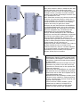
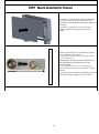
IDENTIFICAZIONE UNITÀ -
IDENTIFICATION OF THE UNIT
- KENNDATEN DER EINHEIT -
IDENTIFICATION DE L'UNITE-
IDENTIFICACIÓN DE LA UNIDAD
Le unità GRIMPER FAN
sono dotate di una
targhetta posta sul fianco
della macchina che
identifica:
GRIMPER FAN units
feature a dataplate
located on one side of
the appliance, showing:
Seitlich von den Geräten
der Einheit GRIMPER FAN
befindet sich ein
Typenschild mit
folgenden Kenndaten:
Sur chaque unité GRIMPER FAN
est apposée une plaquette
d'identification (autrement dit
signalétique) sur le côté de
l'unité portant les indications
suivantes:
Las unidades GRIMPER
FAN poseen una tarjeta
situada en el costado de la
máquina que indica:
Indirizzo del Costruttore
Modello
Codice
Tensione di alimentazione
Potenza el. Assorbita
Potenza frigorifera
Potenza termica
Portata aria
Pressione sonora
Peso netto
Numero di matricola
Marcatura CE
Manufacturer's Address
Model
Code
Power supply voltage
Unit power absorption
Cooling capacity
Heating capacity
Air flow
Sound pressure level
Net weight
Serial number
CE Mark
Anschrift des Herstellers
Modell
Code
Anschlussspannung
Motorleistung
Kühlleistung
Wärmeleistung
Luftvolumenstrom
Schalldruck
GEWICHTE
Seriennummer
CE-Kennzeichnung
Adresse du constructeur
Modèle
Code
Tension d'alimentation
Absorption
Puissance frig
Puissance thermique
Débit d'air
Pression acoustique
POIDS
Numéro de série
Marquage CE
Dirección del fabricante
Modelo
Código
Tensión de alimentación
Absorción
Potencia frigorífica
Potencia térmica
Capacidad de aire
Presión sonora
PESOS
Número de serie
Marca CE
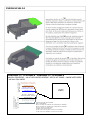
2. CARATTERISTICHE TECNICHE -
TECHNICAL FEATURES
-TECHNISCHE MERKMALE -
CARACTERISTIQUES TECHNIQUES -
CARACTERÍSTICAS TÉCNICAS
La struttura della macchina è realizzata in lamiera zincata di spessore 0,8-1 mm.
I filtri dell’aria sono di classe G1 e possono essere agevolmente rimossi, per consentirne un’adeguata pulizia e manutenzione.
L’isolamento acustico e termico della macchina è realizzato in materiale CL1 – M1.
La batteria di scambio termico è realizzata con tubi di rame e collettori in ottone, mandrinati su alette corrugate di alluminio.
Gli attacchi hanno filettatura 1/2” Gas femmina.
La bacinella di raccolta condensa è anch’essa in lamiera zincata e verniciata, può essere rimossa dalla struttura.
Griglia di mandata e ventilatore in alluminio.
The unit frame is made of 0,8-1 mm gauge metal sheet.
Class G1 air filters designed for easy removal for trouble-free cleaning and maintenance purposes.
Acoustic and thermal insulation is provided by CL1 – M1 material.
The exchanger coil is composed of copper tubes and brass
headers; the tubes are mechanically expanded into corrugated
aluminium fin collars. Coil connectors with 1/2” Gas female.
Equipped with a removable galvanised steel condensate drain pan.
Outlet grille and fan blower made in aluminum.
Die Struktur der Maschine besteht aus 0,8-1 mm von starkem verzinktem Stahlblech.
Die Luftfilter sind in Klasse G1 und können für eine korrekte Reinigung und Wartung problemlos ausgebaut werden.
Die Schall- und Wärmeisolierung der Maschine besteht aus CL1 – M1 Material.
Der Wärmetauscher ist aus Kupfer und Messing Mannigfaltigkeiten, die an gewellten Aluminiumrippen aufgedornt sind.
Die Anschlüsse haben ½“ Gas Female-Außengewinde.
Die Kondensatwanne ist ebenfalls aus lackiertem und verzinktem Blech oder, und kann herausgenommen werden.
Auslassgitter und Gebläse aus Aluminium .
La structure de la machine est réalisée en tôle d’acier zinguée de 0,8-1 mm d’épaisseur.
Les filtres à air sont de classe G1 sont démontables pour faciliter leur entretien et nettoyage.
L’isolation acoustique et thermique est réalisée en CL1 – M1 isolation .
La batterie d’échange thermique est réalisée avec des tubes cuivre et des collecteurs en Laiton sur des ailettes d’aluminium
pliées. Les raccords ont un filetage au pas du 1/2" GAS femelle.
Le bac à condensas amovible est lui aussi fabriqué en tôle galvanisée et en acier peint.
En configuration standard, les unités sont livrées avec un bornier embarqué.
Grille d'évacuation et ventilateur en aluminium.
La estructura de la máquina está hecha en chapa galvanizada con un espesor de 0,8-1 mm.
Los filtros del aire son de clase G1 y pueden ser fácilmente quitados, para permitir una adecuada limpieza y manutención
El aislamiento acústico y térmico de la máquina es de material CL1 – M1.
La batería de intercambio térmico está hecha de tubos de cobre y conexiones en Brass, con aletas corrugadas de aluminio. Las
conexiones son del tipo ½” GF.
El recipiente para la evacuación de la condensación es también en chapa galvanizada o pintada y
puede ser quitado de la
estructura.
Rejilla de salida y ventilador en aluminio.

9
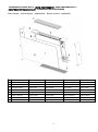
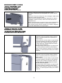
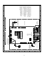
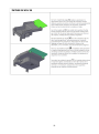
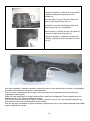
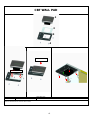
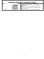
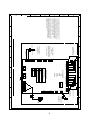
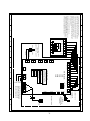
COMPONENTI PRINCIPALI -
MAIN COMPONENTS
- HAUPTBESTANDTEILE –
COMPOSANTES PRINCIPALES
- COMPONENTES PRINCIPALES
Parti esterne – External parts – Außenteileb - Parties externes - Außenteile
1 Fianco laterale destro
Right-hand side flank
Rechtes Seitenteil
Panneau latéral droit
Panel lateral derecho
2 Fianco laterale sinistro
Left-hand side flank
Linkes Seitenteil
Panneau latéral gauche
Panel lateral izquierdo
3 Ventilatore
Fandeck
Lüftereinheit
Groupe ventilateur
Grupo ventilador
4 Vaschetta ausiliaria
Auxiliary drain
Hilfstropfschale
Bac auxiliaire
Bandeja auxiliar
5 Filtro
Filter
Filter
Filtre
Filtro
6 Pannello frontale
Front panel
Frontplatte
Panneau avant
Panel frontal
7 Griglia in alluminio
Aluminum grille
Aluminiumgitter
Grille en aluminium
Rejilla de aluminio
8 Scatola elettrica
Electric box
Elektrische Box
Boîte électrique
Caja electrica
9 Controllo a bordo unità
Built-in control
Eingebaute Steuerung
Contrôle intégré
Control incorporado

10
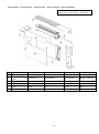
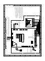
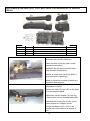
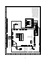
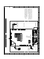
Parti interne – Internal parts – Interne Teile - Parties internes - Partes internas.
1 Fianco interno Internal flank innere Flanke flanc interne flanco interno
2 Scambiatore principale
Main heat-exchanger
Hauptwärmetauscher
Echangeur principal
Batería principal
3 Vaschetta raccolta
condensa
Condensate tray
Kondensatwanne
Bac à condensats
Bandeja condensación
4 Ventilatore
Fandeck
Lüftereinheit
Groupe ventilateur
Grupo ventilador
5 Griglia in alluminio
Aluminum grille
Aluminiumgitter
Grille en aluminium
Rejilla de aluminio
6 Pannelli
Panels
Feld
Panneau
Panel
7 Scatola elettrica
Electric box
Elektrische Box
Boîte électrique
Caja electrica
Unità verticale –
Vertical unit
–
Vertikale Einheit -
Unité verticale
- Unidad vertical.

11
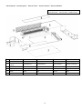
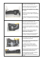
Parti interne – Internal parts – Interne Teile - Parties internes - Partes internas.
1 Fianco interno Internal flank innere Flanke flanc interne flanco interno
2 Scambiatore principale
Main heat-exchanger
Hauptwärmetauscher
Echangeur principal
Batería principal
3 Vaschetta raccolta
condensa
Condensate tray
Kondensatwanne
Bac à condensats
Bandeja condensación
4 Ventilatore
Fandeck
Lüftereinheit
Groupe ventilateur
Grupo ventilador
5 Griglia in alluminio
Aluminum grille
Aluminiumgitter
Grille en aluminium
Rejilla de aluminio
6 Pannelli
Panels
Feld
Panneau
Panel
7 Scatola elettrica
Electric box
Elektrische Box
Boîte électrique
Caja electrica
Unità orizzontale –
Horizontal unit
Horizontale Einheit -
Unité horizontale
- Unidad horizontal.

12
(*) I valori dichiarati sono relativi ai settaggi standard, pertanto relativi a 1500, 900 e 600 RPM. E’ sempre possibile andare a modificare le portate dell’aria, cambiando i
settaggi dei dipswitch delle scheda elettronica
(*) Declared values are relative to standard settings at 1500, 900 and 600 RPM. It is always possible to change the air flow, changing dip switch setting in the PCB.
(*) Die angegebenen Werte beziehen sich auf die Standardeinstellungen bei 1500, 900 und 600 RPM. Es ist immer möglich, den Luftstrom zu ändern, indem die Dip-
Schalter-Einstellung in der Leiterplatte geändert wird.
(*) Les valeurs déclarées sont relatives aux réglages standard à 1500, 900 et 600 RPM. Il est toujours possible de modifier le débit d’air en modifiant le réglage du
commutateur DIP dans la carte électronique principale.
(*) Los valores declarados son relativos a la configuración estándar a 1500, 900 y 600 RPM. Siempre es posible cambiar el flujo de aire, cambiando la configuración del
interruptor DIP en la PCB.
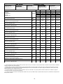
DATI TECNICI-TECHNICAL DATA-TECHNISCHE DATEN-DONNÉES TECNIQUES–DATOS TÉCNICOS
Impianto a 2 tubi –
2 pipe system
– 2 Leiter-System -
Installation 2 tubes
– Instalación 2 tubos
RAFFRESCAMENTO
T.ambiente:27 °C - 47 % UR ,
T. acqua(in/out):7/12°C
COOLING MODE
Room:27° C – 47% R.H.
Water temp. (in/out):7/12°C
KÜHLBETRIEB
Raum: 27°C– 47% R.F.
Wassertemp. (in/out):7/12°C
REFROIDISSEMENT
Ambiante:27 °C - 47 % HR
Temp.eau(entrée/sortie):
7/12 °C
ENFRIAMIENTO
Ambiente: 27 °C - 47 % UR
T. agua(in/out):7/12°C
Speed
09
18
27
34
Portata aria
Air flow rate
Luftvolumenstrom
Débit d'air
Capacidad de aire
m^3/h
Supermax 250 390 510 620
Max (*) 180 315 450 540
Med (*)
120
230
350
450
Min (*) 80 155 240 310
Static 10 18 25 32
Potenza frigorifera totale -
Total cooling capacity
-Kühlleistung -
Puissance frig.
Totale
-Potencia frigorífica total KW Supermax 1.19 2.12 2.90 3.73
Potenza frigorifera sensibile -
Sensible capacity-
Sens. Kühlleistung
Puissance
sensible
(Kw)
-
Potencia frigorífica sensible KW Supermax 0.87 1.56 2.16 2.97
Portata acqua -
Water flow rate –
Wasservolumenstrom –
Débit d'eau
-
Capacidad de agua l/h Supermax 204 364 498 639
Perdita di carico -
Pressure drop –
Wasserdruckverlust
Perte de charge -
Pérdida de presión kPa Supermax 15.1 10.2 20.9 19.9
Potenza frigorifera totale -
Total cooling capacity
-Kühlleistung -
Puissance frig.
Totale
-Potencia frigorífica total KW max 0.88 1.81 2.70 3.38
Potenza frigorifera sensibile -
Sensible capacity-
Sens. Kühlleistung
Puissance
sensible
(Kw)
-
Potencia frigorífica sensible KW max 0.69 1.35 2.00 2.70
Portata acqua -
Water flow rate –
Wasservolumenstrom –
Débit d'eau
-
Capacidad de agua l/h max 151 311 463 580
Perdita di carico -
Pressure drop –
Wasserdruckverlust
Perte de charge -
Pérdida de presión kPa max 13.1 8.2 19.0 18.7
Potenza frigorifera totale -
Total cooling capacity
-Kühlleistung -
Puissance frig.
Totale
-Potencia frigorífica total KW med 0.79 1.45 2.20 2.75
Potenza frigorifera sensibile -
Sensible capacity-
Sens. Kühlleistung
Puissance
sensible
(Kw)
-
Potencia frigorífica sensible KW med 0.60 1.10 1.68 2.30
Portata acqua -
Water flow rate –
Wasservolumenstrom –
Débit d'eau
-
Capacidad de agua l/h med 136 249 377 472
Perdita di carico -
Pressure drop –
Wasserdruckverlust
Perte de charge -
Pérdida de presión kPa med 7.2 6.0 16.5 13.2
Potenza frigorifera totale -
Total cooling capacity
-Kühlleistung -
Puissance frig.
Totale
-Potencia frigorífica total KW min 0.45 0.98 1.70 2.13
Potenza frigorifera sensibile -
Sensible capacity-
Sens. Kühlleistung
Puissance
sensible
(Kw)
-
Potencia frigorífica sensible KW min 0.30 0.70 1.25 1.70
Portata acqua -
Water flow rate –
Wasservolumenstrom –
Débit d'eau
-
Capacidad de agua l/h min 77 168 292 365
Perdita di carico -
Pressure drop –
Wasserdruckverlust
Perte de charge -
Pérdida de presión kPa min 4.1 4.1 13.0 10.0
Potenza frigorifera totale -
Total cooling capacity
-Kühlleistung -
Puissance frig.
Totale
-Potencia frigorífica total KW Static 0.10 0.14 0.20 0.23
Potenza frigorifera sensibile -
Sensible capacity-
Sens. Kühlleistung
Puissance
sensible
(Kw)
-
Potencia frigorífica sensible KW Static 0.08 0.11 0.16 0.20
Portata acqua -
Water flow rate –
Wasservolumenstrom –
Débit d'eau
-
Capacidad de agua
l/h Static 151 311 463 580
Perdita di carico -
Pressure drop –
Wasserdruckverlust
Perte de charge -
Pérdida de presión
kPa Static 13.1 8.2 19.0 18.7

13
(*) I valori dichiarati sono relativi ai settaggi standard, pertanto relativi a 1500, 900 e 600 RPM. E’ sempre possibile andare a modificare le portate dell’aria, cambiando i
settaggi dei dipswitch delle scheda elettronica
(*) Declared values are relative to standard settings at 1500, 900 and 600 RPM. It is always possible to change the air flow, changing dip switch setting in the PCB.
(*) Die angegebenen Werte beziehen sich auf die Standardeinstellungen bei 1500, 900 und 600 RPM. Es ist immer möglich, den Luftstrom zu ändern, indem die Dip-
Schalter-Einstellung in der Leiterplatte geändert wird.
(*) Les valeurs déclarées sont relatives aux réglages standard à 1500, 900 et 600 RPM. Il est toujours possible de modifier le débit d’air en modifiant le réglage du
commutateur DIP dans la carte électronique principale.
(*) Los valores declarados son relativos a la configuración estándar a 1500, 900 y 600 RPM. Siempre es posible cambiar el flujo de aire, cambiando la configuración del
interruptor DIP en la PCB.
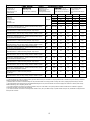
Impianto a 2 tubi –
2 pipe system
– 2 Leiter-System -
Installation 2 tubes
– Instalación 2 tubos
RISCALDAMENTO
T.ambiente:20 °C,
T. acqua in:50°C,
portata acqua come in
condizionamento
HEATING MODE
Room:20° C.
Water temp. in:50.
same water flow conditioning
HEIZUNG
Raumtemp.: 20°C
Wassertemp.IN: 50°C
dasselbe Wasser
strömungsbeeinflussende
CHAUFFAGE
Temp. ambiante : 20 °C
Temp.de l’eau (entrée):50 °C
même débit d'eau conditionné
CALEFACCIÓN
Temp. ambiente: 20°C
T. agua (in):50°C
misma acondicionado flujo de
agua
Speed
09
18
27
34
Portata aria
Air flow rate
Luftvolumenstrom
Débit d'air
Capacidad de aire
m^3/h
Supermax
250
390
510
620
Max (*) 180 315 450 540
Med (*) 120 230 350 450
Min (*) 80 155 240 310
Static
10
18
25
32
Potenza termica scamb. princip.
Main exchanger thermal capacity
Wärmeleistung, Hauptwärmetauscher -
Puissance thermique échang. princip
.
Potencia térmica intercambiador principal
KW Supermax 1.55 2.71 3.71 4.71
Portata acqua scamb. princip. -
Main exchanger water flow rate
- Wasserfluss,
Hauptwärmetauscher –
Débit d’eau échang. Principal
- Flujo de agua l/h Supermax 204 364 498 639
Perdita di carico scamb. princ. -
Main exchanger pressure drop
- Druckverlust,
Hauptwärmetauscher -
Perte de charge échang. principa
l - Pérdida de presión kPa Supermax 13.5 8.1 16.8 16.9
Potenza termica scamb. princip.
Main exchanger thermal capacity
Wärmeleistung, Hauptwärmetauscher -
Puissance thermique échang. princip
.
Potencia térmica intercambiador principal
KW max 1.10 2.40 3.20 4.23
Portata acqua scamb. princip. -
Main exchanger water flow rate
- Wasserfluss,
Hauptwärmetauscher –
Débit d’eau échang. Principal
- Flujo de agua l/h max 151 311 463 580
Perdita di carico scamb. princ. -
Main exchanger pressure drop
- Druckverlust,
Hauptwärmetauscher -
Perte de charge échang. principa
l - Pérdida de presión kPa max 12.2 6.8 15.8 15.5
Potenza termica scamb. princip.
Main exchanger thermal capacity
Wärmeleistung, Hauptwärmetauscher -
Puissance thermique échang. princip
.
Potencia térmica intercambiador principal
KW med 0.90 1.50 2.40 3.40
Portata acqua scamb. princip. -
Main exchanger water flow rate
- Wasserfluss,
Hauptwärmetauscher –
Débit d’eau échang. Principal
- Flujo de agua l/h med 136 249 377 472
Perdita di carico scamb. princ. -
Main exchanger pressure drop
- Druckverlust,
Hauptwärmetauscher -
Perte de charge échang. principa
l - Pérdida de presión kPa med 6.9 5.7 14.7 12.1
Potenza termica scamb. princip.
Main exchanger thermal capacity
Wärmeleistung, Hauptwärmetauscher -
Puissance thermique échang. princip
.
Potencia térmica intercambiador principal
KW min 0.61 1.16 1.75 2.41
Portata acqua scamb. princip. -
Main exchanger water flow rate
- Wasserfluss,
Hauptwärmetauscher –
Débit d’eau échang. Principal
- Flujo de agua l/h min 77 168 292 365
Perdita di carico scamb. princ. -
Main exchanger pressure drop
- Druckverlust,
Hauptwärmetauscher -
Perte de charge échang. principa
l - Pérdida de presión kPa min 4.0 3.9 10.0 8.2
Potenza termica scamb. princip.
Main exchanger thermal capacity
Wärmeleistung, Hauptwärmetauscher -
Puissance thermique échang. princip
.
Potencia térmica intercambiador principal
KW Static 0.22 0.25 0.3 0.38
Portata acqua scamb. princip. -
Main exchanger water flow rate
- Wasserfluss,
Hauptwärmetauscher –
Débit d’eau échang. Principal
-
Flujo de agua
l/h Static 151 311 463 580
Perdita di carico scamb. princ. -
Main exchanger pressure drop
- Druckverlust,
Hauptwärmetauscher -
Perte de charge échang. principa
l - Pérdida de presión kPa Static 12.2 6.8 15.8 15.5

14
(*) I valori dichiarati sono relativi ai settaggi standard, pertanto relativi a 1500, 900 e 600 RPM. E’ sempre possibile andare a modificare le portate dell’aria, cambiando i
settaggi dei dipswitch delle scheda elettronica
(*) Declared values are relative to standard settings at 1500, 900 and 600 RPM. It is always possible to change the air flow, changing dip switch setting in the PCB.
(*) Die angegebenen Werte beziehen sich auf die Standardeinstellungen bei 1500, 900 und 600 RPM. Es ist immer möglich, den Luftstrom zu ändern, indem die Dip-
Schalter-Einstellung in der Leiterplatte geändert wird.
(*) Les valeurs déclarées sont relatives aux réglages standard à 1500, 900 et 600 RPM. Il est toujours possible de modifier le débit d’air en modifiant le réglage du
commutateur DIP dans la carte électronique principale.
(*) Los valores declarados son relativos a la configuración estándar a 1500, 900 y 600 RPM. Siempre es posible cambiar el flujo de aire, cambiando la configuración del
interruptor DIP en la PCB.
Impianto a 4 tubi –
4 pipe system
– 4 Leiter-System -
Installation 4 tubes
– Instalación 4 tubos
RAFFRESCAMENTO
T.ambiente:27 °C - 47 % UR ,
T. acqua(in/out):7/12°C
COOLING MODE
Room:27° C – 47% R.H.
Water temp. (in/out):7/12°C
KÜHLBETRIEB
Raum: 27°C– 47% R.F.
Wassertemp. (in/out):7/12°C
REFROIDISSEMENT
Ambiante:27 °C - 47 % HR
Temp.eau(entrée/sortie):
7/12 °C
ENFRIAMIENTO
Ambiente: 27 °C - 47 % UR
T. agua(in/out):7/12°C
Speed
09
18
27
34
Portata aria
Air flow rate
Luftvolumenstrom
Débit d'air
Capacidad de aire
m^3/h
Supermax
250
390
510
620
Max (*) 180 315 450 540
Med (*) 120 230 350 450
Min (*) 80 155 240 310
Static
10
18
25
32
Potenza frigorifera totale -
Total cooling capacity
-Kühlleistung -
Puissance frig.
Totale
-Potencia frigorífica total KW Supermax 1.19 2.12 2.90 3.73
Potenza frigorifera sensibile -
Sensible capacity-
Sens. Kühlleistung
Puissance
sensible
(Kw)
-
Potencia frigorífica sensible KW Supermax 0.87 1.56 2.16 2.97
Portata acqua -
Water flow rate –
Wasservolumenstrom –
Débit d'eau
-
Capacidad de agua l/h Supermax 204 364 498 639
Perdita di carico -
Pressure drop –
Wasserdruckverlust
Perte de charge -
Pérdida de presión kPa Supermax 15.1 10.2 20.9 19.9
Potenza frigorifera totale -
Total cooling capacity
-Kühlleistung -
Puissance frig.
Totale
-Potencia frigorífica total KW max 0.88 1.81 2.70 3.38
Potenza frigorifera sensibile -
Sensible capacity-
Sens. Kühlleistung
Puissance
sensible
(Kw)
-
Potencia frigorífica sensible KW max 0.69 1.35 2.00 2.70
Portata acqua -
Water flow rate –
Wasservolumenstrom –
Débit d'eau
-
Capacidad de agua l/h max 151 311 463 580
Perdita di carico -
Pressure drop –
Wasserdruckverlust
Perte de charge -
Pérdida de presión kPa max 13.1 8.2 19.0 18.7
Potenza frigorifera totale -
Total cooling capacity
-Kühlleistung -
Puissance frig.
Totale
-Potencia frigorífica total KW med 0.79 1.45 2.20 2.75
Potenza frigorifera sensibile -
Sensible capacity-
Sens. Kühlleistung
Puissance
sensible
(Kw)
-
Potencia frigorífica sensible KW med 0.60 1.10 1.68 2.30
Portata acqua -
Water flow rate –
Wasservolumenstrom –
Débit d'eau
-
Capacidad de agua l/h med 136 249 377 472
Perdita di carico -
Pressure drop –
Wasserdruckverlust
Perte de charge -
Pérdida de presión kPa med 7.2 6.0 16.5 13.2
Potenza frigorifera totale -
Total cooling capacity
-Kühlleistung -
Puissance frig.
Totale
-Potencia frigorífica total KW min 0.45 0.98 1.70 2.13
Potenza frigorifera sensibile -
Sensible capacity-
Sens. Kühlleistung
Puissance
sensible
(Kw)
-
Potencia frigorífica sensible KW min 0.30 0.70 1.25 1.70
Portata acqua -
Water flow rate –
Wasservolumenstrom –
Débit d'eau
-
Capacidad de agua l/h min 77 168 292 365
Perdita di carico -
Pressure drop –
Wasserdruckverlust
Perte de charge -
Pérdida de presión kPa min 4.1 4.1 13.0 10.0
Potenza frigorifera totale -
Total cooling capacity
-Kühlleistung -
Puissance frig.
Totale
-Potencia frigorífica total KW Static 0.10 0.14 0.20 0.23
Potenza frigorifera sensibile -
Sensible capacity-
Sens. Kühlleistung
Puissance
sensible
(Kw)
-
Potencia frigorífica sensible KW Static 0.08 0.11 0.16 0.20
Portata acqua -
Water flow rate –
Wasservolumenstrom –
Débit d'eau
-
Capacidad de agua
l/h Static 151 311 463 580
Perdita di carico -
Pressure drop –
Wasserdruckverlust
Perte de charge -
Pérdida de presión
kPa Static 13.1 8.2 19.0 18.7

15
(*) I valori dichiarati sono relativi ai settaggi standard, pertanto relativi a 1500, 900 e 600 RPM. E’ sempre possibile andare a modificare le portate dell’aria, cambiando i
settaggi dei dipswitch delle scheda elettronica
(*) Declared values are relative to standard settings at 1500, 900 and 600 RPM. It is always possible to change the air flow, changing dip switch setting in the PCB.
(*) Die angegebenen Werte beziehen sich auf die Standardeinstellungen bei 1500, 900 und 600 RPM. Es ist immer möglich, den Luftstrom zu ändern, indem die Dip-
Schalter-Einstellung in der Leiterplatte geändert wird.
(*) Les valeurs déclarées sont relatives aux réglages standard à 1500, 900 et 600 RPM. Il est toujours possible de modifier le débit d’air en modifiant le réglage du
commutateur DIP dans la carte électronique principale.
(*) Los valores declarados son relativos a la configuración estándar a 1500, 900 y 600 RPM. Siempre es posible cambiar el flujo de aire, cambiando la configuración del
interruptor DIP en la PCB.
Impianto a 4 tubi –
4 pipe system
– 4 Leiter-System -
Installation 4 tubes
– Instalación 4 tubos
RISCALDAMENTO
T.ambiente:20 °C,
T. acqua in:50°C,
portata acqua come in
condizionamento
HEATING MODE
Room:20° C.
Water temp. in:50.
same water flow conditioning
HEIZUNG
Raumtemp.: 20°C
Wassertemp.IN: 50°C
dasselbe Wasser
strömungsbeeinflussende
CHAUFFAGE
Temp. ambiante : 20 °C
Temp.de l’eau (entrée):50 °C
même débit d'eau conditionné
CALEFACCIÓN
Temp. ambiente: 20°C
T. agua (in):50°C
misma acondicionado flujo de
agua
Speed
09
18
27
34
Portata aria
Air flow rate
Luftvolumenstrom
Débit d'air
Capacidad de aire
m^3/h
Supermax
250
390
510
620
Max (*) 180 315 450 540
Med (*) 120 230 350 450
Min (*) 80 155 240 310
Static
10
18
25
32
Potenza termica scamb. princip.
Main exchanger thermal capacity
Wärmeleistung, Hauptwärmetauscher -
Puissance thermique échang. princip
.
Potencia térmica intercambiador principal
KW Supermax 1.55 2.71 3.71 4.71
Portata acqua scamb. princip. -
Main exchanger water flow rate
- Wasserfluss,
Hauptwärmetauscher –
Débit d’eau échang. Principal
- Flujo de agua l/h Supermax 204 364 498 639
Perdita di carico scamb. princ. -
Main exchanger pressure drop
- Druckverlust,
Hauptwärmetauscher -
Perte de charge échang. principa
l - Pérdida de presión kPa Supermax 13.5 8.1 16.8 16.9
Potenza termica scamb. princip.
Main exchanger thermal capacity
Wärmeleistung, Hauptwärmetauscher -
Puissance thermique échang. princip
.
Potencia térmica intercambiador principal
KW max 1.10 2.40 3.20 4.23
Portata acqua scamb. princip. -
Main exchanger water flow rate
- Wasserfluss,
Hauptwärmetauscher –
Débit d’eau échang. Principal
- Flujo de agua l/h max 151 311 463 580
Perdita di carico scamb. princ. -
Main exchanger pressure drop
- Druckverlust,
Hauptwärmetauscher -
Perte de charge échang. principa
l - Pérdida de presión kPa max 12.2 6.8 15.8 15.5
Potenza termica scamb. princip.
Main exchanger thermal capacity
Wärmeleistung, Hauptwärmetauscher -
Puissance thermique échang. princip
.
Potencia térmica intercambiador principal
KW med 0.90 1.50 2.40 3.40
Portata acqua scamb. princip. -
Main exchanger water flow rate
- Wasserfluss,
Hauptwärmetauscher –
Débit d’eau échang. Principal
- Flujo de agua l/h med 136 249 377 472
Perdita di carico scamb. princ. -
Main exchanger pressure drop
- Druckverlust,
Hauptwärmetauscher -
Perte de charge échang. principa
l - Pérdida de presión kPa med 6.9 5.7 14.7 12.1
Potenza termica scamb. princip.
Main exchanger thermal capacity
Wärmeleistung, Hauptwärmetauscher -
Puissance thermique échang. princip
.
Potencia térmica intercambiador principal
KW min 0.61 1.16 1.75 2.41
Portata acqua scamb. princip. -
Main exchanger water flow rate
- Wasserfluss,
Hauptwärmetauscher –
Débit d’eau échang. Principal
- Flujo de agua l/h min 77 168 292 365
Perdita di carico scamb. princ. -
Main exchanger pressure drop
- Druckverlust,
Hauptwärmetauscher -
Perte de charge échang. principa
l - Pérdida de presión kPa min 4.0 3.9 10.0 8.2
Potenza termica scamb. princip.
Main exchanger thermal capacity
Wärmeleistung, Hauptwärmetauscher -
Puissance thermique échang. princip
.
Potencia térmica intercambiador principal
KW Static 0.22 0.25 0.3 0.38
Portata acqua scamb. princip. -
Main exchanger water flow rate
- Wasserfluss,
Hauptwärmetauscher –
Débit d’eau échang. Principal
-
Flujo de agua
l/h Static 151 311 463 580
Perdita di carico scamb. princ. -
Main exchanger pressure drop
- Druckverlust,
Hauptwärmetauscher -
Perte de charge échang. principa
l - Pérdida de presión kPa Static 12.2 6.8 15.8 15.5

16
(*) I valori dichiarati sono relativi ai settaggi standard, pertanto relativi a 1500, 900 e 600 RPM. E’ sempre possibile andare a modificare le portate dell’aria, cambiando i
settaggi dei dipswitch delle scheda elettronica
(*) Declared values are relative to standard settings at 1500, 900 and 600 RPM. It is always possible to change the air flow, changing dip switch setting in the PCB.
(*) Die angegebenen Werte beziehen sich auf die Standardeinstellungen bei 1500, 900 und 600 RPM. Es ist immer möglich, den Luftstrom zu ändern, indem die Dip-
Schalter-Einstellung in der Leiterplatte geändert wird.
(*) Les valeurs déclarées sont relatives aux réglages standard à 1500, 900 et 600 RPM. Il est toujours possible de modifier le débit d’air en modifiant le réglage du
commutateur DIP dans la carte électronique principale.
(*) Los valores declarados son relativos a la configuración estándar a 1500, 900 y 600 RPM. Siempre es posible cambiar el flujo de aire, cambiando la configuración del
interruptor DIP en la PCB.
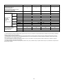
09
18
27
34
Numero ranghi scambiatore principale
Number of rows of main coil
Reihenzahl Hauptregister
Nombre de rangées de la batterie principale
Número rangos batería principal
2 2 2 2
Attacchi batteria –
Coil connection
Batterieverbindungen -
Connexions de la batteri
e -
Conexiones de la batería
1/2” GF 1/2” GF 1/2” GF 1/2” GF
Assorb del motore
motor input
Motorleistung
Absorption du
moteur
Absorción del motor
Supermax W 20 22 24 27
V/H/Ph
230 V – 50 Hz - 1Ph
MAX (*) W 12 13 14 17
V/H/Ph 230 V – 50 Hz - 1Ph
MED (*) W 5 6 7 10
V/H/Ph
230 V – 50 Hz - 1Ph
MIN (*) W 3 4 5 8
V/H/Ph 230 V – 50 Hz - 1Ph
Static
W
0
0
0
0
V/H/Ph
230 V – 50 Hz - 1Ph
Resistenza elettrico –
Electric
heater
- Elektrische Heizung –
Réchauffeur électrique
-
Resistencia eléctrica
W 50 50 100 100
A 0.22 0.22 0.45 0.45
V/H/Ph 230 V – 50 Hz - 1Ph

17
DATI DI RUMOROSITA’ -
NOISE LEVEL DATA
- LÄRMBELASTUNG -
DONNEES BRUIT –
NIVEL DE RUIDO
Potenza sonora -
Sound power
- Schallleistung -
Puissance
acoustique
Potencia sonora Pressione sonora -
Sound pressare
Schalldruck -
Pression acoustique
Presión sonora
(1)
DC SERIES TOT
[dB(A)] DC SERIES TOT
[dB(A)]
09
Supermax 55.0
09
Supermax 38.0
MAX (*) 51.3 MAX (*) 34.3
MED (*) 44.6 MED (*) 27.6
MIN (*) 37.5 MIN (*) 20.5
Static 0 Static 0
18
Supermax 56.0
18
Supermax 39.0
MAX (*) 52.2 MAX (*) 35.2
MED (*) 45.5 MED (*) 28.5
MIN (*) 38.6 MIN (*) 21.6
Static 0 Static 0
27
Supermax 57.1
27
Supermax 40.1
MAX (*) 52.4 MAX (*) 35.4
MED (*) 46.6 MED (*) 29.6
MIN (*) 40.5 MIN (*) 23.5
Static 0 Static 0
34
Supermax 58.3
34
Supermax 41.3
MAX (*) 53.3 MAX (*) 36.3
MED (*) 48.6 MED (*) 31.6
MIN (*) 38.7 MIN (*) 21.7
Static 0 Static 0
(1) Pressione sonora misurata a 2m.
(1) Sound pressure at 2m.
(1) Schalldruck bei 2m
(1)
Pression sonore à 2m.
(1) Presión sonora a 2m.
(*) I valori dichiarati sono relativi ai settaggi standard, pertanto relativi a 1500, 900 e 600 RPM. E’ sempre possibile andare a modificare le portate dell’aria, cambiando i
settaggi dei dipswitch delle scheda elettronica
(*) Declared values are relative to standard settings at 1500, 900 and 600 RPM. It is always possible to change the air flow, changing dip switch setting in the PCB.
(*) Die angegebenen Werte beziehen sich auf die Standardeinstellungen bei 1500, 900 und 600 RPM. Es ist immer möglich, den Luftstrom zu ändern, indem die Dip-
Schalter-Einstellung in der Leiterplatte geändert wird.
(*) Les valeurs déclarées sont relatives aux réglages standard à 1500, 900 et 600 RPM. Il est toujours possible de modifier le débit d’air en modifiant le réglage du
commutateur DIP dans la carte électronique principale.
(*) Los valores declarados son relativos a la configuración estándar a 1500, 900 y 600 RPM. Siempre es posible cambiar el flujo de aire, cambiando la configuración del
interruptor DIP en la PCB.

18
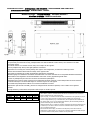
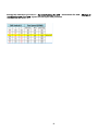
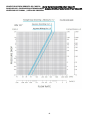
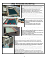
DIMENSIONI E PESI –
DIMENSIONS AND WEIGHTS –
ABMESSUNGEN UND GEWICHTE –
DIMENSIONS ET POIDS -
DIMENSIONES Y PESOS
Per macchina destra (DX), si intende una macchina che abbia le connessioni idrauliche sul
fianco destro, qualora ci si metta davanti alla bocca di mandata del fancoil fissato alla
parete. Analogamente per unità sinistra (SX)
Right unit (DX), is a machine that has the water connections on the right side, if you put
in front of the outlet of the fan coil fixed to the wall. Similarly for units left (SX)
Um die richtige Maschine (DX), ist eine Maschine, die die hydraulischen Anschlüsse auf
der rechten Seite, wo wir vor dem Ausgang der Maschine, die an der Wand gestellt hat
gemeint. Ähnliches gilt für Einheiten übrig (SX)
Machine à droite (DX), on entend une machine comportant des raccords hydrauliques sur
le côté droit, où l'on met en face de la sortie de la machine fixée à la paroi. De même
pour les unités à gauche (SX)
Para mecanizar derecha (DX), se entiende una máquina que tiene las conexiones
hidráulicas en el lado derecho, en el que poner en frente de la salida de la máquina fija a
la pared. De manera similar para las unidades a la izquierda (SX)
Modelli verticali –
Vertical Models
– Vertikale Modelle –
Modèles verticaux
- Modelos verticales
09
18
27
34
A (mm)
681
873
1065
1257
Kg
18
21
24
27
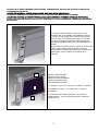
L’unità è predisposta di fabbrica, in modo da avere le connessioni idrauliche sul lato destro.
Le operazioni per trasformare l’unità, predisponendola con attacchi idraulici sul lato sinistro, sono indicate in una delle
successive sezioni.
La scatola elettrica e il controllo a bordo unità, sono sempre sul lato opposto.
Unit is predisposed by factory with right hydraulic connections.
Operations for reversing the unit and passing from right to left configuration, as indicated in following section.
Electric box and build-in thermostat are always in the opposite side.
Das Gerät ist werkseitig mit rechten hydraulischen Anschlüssen ausgestattet.
Bedienvorgänge zum Umkehren des Geräts und Weiterleiten von rechts nach links wie im folgenden Abschnitt beschrieben.
Elektrokasten und eingebauter Thermostat befinden sich immer auf der gegenüberliegenden Seite.
L'unité est prédisposée par l'usine avec les bons raccordements hydrauliques.
Opérations pour inverser l’unité et passer de la configuration de droite à gauche, comme indiqué dans la section suivante.
Le boîtier électrique et le thermostat intégré se trouvent toujours du côté opposé.
La unidad está predispuesta de fábrica con conexiones hidráulicas correctas.
Operaciones para invertir la unidad y pasar de la configuración de derecha a izquierda, como se indica en la siguiente
sección.
La caja eléctrica y el termostato incorporado están siempre en el lado opuesto.

19
Per macchina destra (DX), si intende una macchina che abbia le connessioni idrauliche sul
fianco destro, qualora ci si metta davanti alla bocca di mandata del fancoil fissato alla parete.
Analogamente per unità sinistra (SX)
Right unit (DX), is a machine that has the water connections on the right side, if you put in
front of the outlet of the fan coil fixed to the wall. Similarly for units left (SX)
Um die richtige Maschine (DX), ist eine Maschine, die die hydraulischen Anschlüsse auf der
rechten Seite, wo wir vor dem Ausgang der Maschine, die an der Wand gestellt hat gemeint.
Ähnliches gilt für Einheiten übrig (SX)
Machine à droite (DX), on entend une machine comportant des raccords hydrauliques sur le
côté droit, où l'on met en face de la sortie de la machine fixée à la paroi. De même pour les
unités à gauche (SX)
Para mecanizar derecha (DX), se entiende una máquina que tiene las conexiones hidráulicas
en el lado derecho, en el que poner en frente de la salida de la máquina fija a la pared. De
manera similar para las unidades a la izquierda (SX)
Modelli orizzontali –
Horizontal Models
– Horizontale Modelle –
Modèles horizontaux
- Modelos horizontales
09
18
27
34
A (mm)
681
873
1065
1257
Kg
18
21
24
27
L’unità può avere attacchi idraulici solo sul lato destro.
La scatola elettrica è sul lato opposto. La vaschetta raccolta condensa ausiliaria non è prevista.
The unit can have hydraulic connections only on the right side.
The electrical box is on the opposite side. Auxiliary drain pan is not used.
Das Gerät kann nur auf der rechten Seite hydraulische Anschlüsse haben.
Die elektrische Box befindet sich auf der gegenüberliegenden Seite. Zusatzablaufwanne wird nicht verwendet.
L'unité peut avoir des connexions hydrauliques seulement du côté droit.
Le boîtier électrique est du côté opposé. Un bac de récupération auxiliaire n'est pas utilisé.
La unidad solo puede tener conexiones hidráulicas en el lado derecho.
La caja eléctrica está en el lado opuesto. No se utiliza bandeja de drenaje auxiliar.

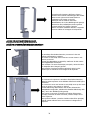
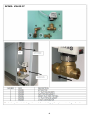
20
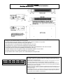
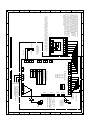
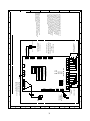
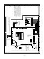
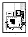
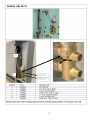
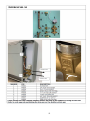
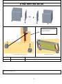
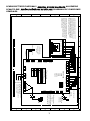
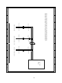
3. ISTRUZIONI PER L’INSTALLAZIONE -
INSTALLATION INSTRUCTIONS
-
INSTALLATIONSANWEISUNGEN -
INSTRUCTIONS POUR L’INSTALLATION
INSTRUCCIONES PARA LA INSTALACIÓN
AVVERTENZE -
WARNINGS
- WICHTIGE HINWEISE –
AVERTISSEMENTS-
ADVERTENCIAS
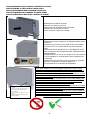
Unità per installazione all'interno.
Per la movimentazione delle unità utilizzare mezzi adeguati come previsto dalla direttiva 2007/30/CE e successive modifiche.
La ditta costruttrice declina
qualsiasi responsabilità per la mancata osservanza delle norme di sicurezza e di prevenzione di
seguito descritte. Declina inoltre ogni responsabilità per danni causati da un uso improprio delle unità e/o da modifiche
eseguite senza autorizzazione.
L’insta
llazione deve essere eseguita da personale specializzato. Nelle operazioni di installazione, usare un abbigliamento idoneo e
antinfortunistico come indicato dalla norma 93/68/CEE e successive.
Rispettare le leggi in vigore nel Paese in cui viene installata
la macchina, relativamente all’uso e allo smaltimento dell’imballo e dei prodotti
impiegati per la pulizia e la manutenzione della macchina.
Prima di mettere in funzione l’unità controllare la perfetta integrità dei vari componenti e dell’intero impianto. Evitare assolutamente di toccare le
parti in movimento.
Non procedere con i lavori di manutenzione e di pulizia, se prima non è stata tolta l’alimentazione elettrica.
Le parti di ricambio devono corrispondere alle esigenze definite dal
costruttore. In caso di smantellamento delle unità, attenersi alle normative
antinquinamento previste.
L’installatore e l’utilizzatore devono tenere conto e porre rimedio a tutti gli altri tipi di rischio connessi con l’uso delle unità nel proprio impianto.
Ad esempio rischi derivanti da ingresso di corpi estranei, oppure convogliamento di gas tossici o infiammabili negli ambienti termoregolati.
Internal installation unit.
When handling the units use appropriate lifting means as specified by directive 2007/30/EEC and subsequent amendments.
The manufacturer declines all liability in the event of failure to observe the safety and precautionary prescriptions set down in
this manual, and all liability for damage caused by improper use and/or authorised modifications.
The fan coil unit must be installed by skilled personnel, who must wear suitable safety apparel during the work as specified
by directive
93/68/EEC and subsequent amendments.
Comply with statutory laws in the Country in which the
appliance is installed concerning the use and disposal of packing materials and the
products utilised for cleaning and maintenance purposes.
Before commissioning the unit check that all the parts and the entire installation is in perfect working order. Do
not touch moving parts under
any circumstances.
Do not proceed with maintenance or cleaning until the electrical power supply has been disconnected.
Spare parts must correspond to the requirements specified by the manufacturer. If the unit is to be scrapp
ed, adhere to the applicable
environmental legislation.
The installer and user must take account or and remedy all the other types of risks associated with the use of the unit in th
e specific plant.
Consider, for example, risks deriving from the ingress of
foreign objects or conveyance of toxic or inflammable gas into the temperature
controlled areas.
Einheit für die Installation im Inneren.
Für die Flurförderung der Einheit müssen geeignete Mittel gemäß der Richtlinie 2007/30
/EWG und deren nachfolgenden Änderungen benutzt
werden.
Der Hersteller ist bei Missachtung der nachfolgenden Sicherheits- und Unfallverhütungsvorschriften nicht haftbar.
Er ist
außerdem für Schäden, die durch einen zweckwidrigen Gebrauch der Einheiten bzw.
durch nicht genehmigte Änderungen
verursacht werden, nicht haftbar.
Die Installation muss durch Fachpersonal vorgenommen werden. Für die Durchführung der Installationsa
rbeiten sind geeignete Kleidung und
persönliche Schutzausrüstungen gemäß der Richtlinie 93/68/EWG und deren nachfolgenden Änderungen vorgeschrieben.
Die im Installationsland des Geräts geltenden Rechtsvorschriften bezüglich Verwendung und Entsorgung der Ve
rpackung und der für die
Reinigung und Wartung des Geräts benutzten Produkte sind strikt zu befolgen.
Vor Inbetriebnahme der Einheit muss die Unversehrtheit der verschiedenen Bauteile und der ganzen Anlage überprüft werden. Die beweglichen
Teile dürfen unter keinen Umständen berührt werden.
Die Wartungs- und Reinigungseingriffe dürfen erst durchgeführt werden, nachdem die Stromzufuhr unterbrochen wurde.
Die Ersatzteile müssen den Vorgaben des Herstellers entsprechen. Bei Verschrottung der Einheit sind die einschlägigen
Umweltschutzbestimmungen zu befolgen.
Der Installateur und der Benutzer müssen sämtliche Gefahren im Zusammenhang mit der Benutzung der Geräte in der eigenen Anlag
e kennen
und entsprechende Abhilfe schaffen. Dazu gehören z.B. Gefahren
infolge Eindringen von Fremdkörpern oder das Einströmen von giftigen oder
brennbaren Gasen in die wärmegeregelten Räume.
La pagina si sta caricando...
La pagina si sta caricando...
La pagina si sta caricando...
La pagina si sta caricando...
La pagina si sta caricando...
La pagina si sta caricando...
La pagina si sta caricando...
La pagina si sta caricando...
La pagina si sta caricando...
La pagina si sta caricando...
La pagina si sta caricando...
La pagina si sta caricando...
La pagina si sta caricando...
La pagina si sta caricando...
La pagina si sta caricando...
La pagina si sta caricando...
La pagina si sta caricando...
La pagina si sta caricando...
La pagina si sta caricando...
La pagina si sta caricando...
La pagina si sta caricando...
La pagina si sta caricando...
La pagina si sta caricando...
La pagina si sta caricando...
La pagina si sta caricando...
La pagina si sta caricando...
La pagina si sta caricando...
La pagina si sta caricando...
La pagina si sta caricando...
La pagina si sta caricando...
La pagina si sta caricando...
La pagina si sta caricando...
La pagina si sta caricando...
La pagina si sta caricando...
La pagina si sta caricando...
La pagina si sta caricando...
La pagina si sta caricando...
La pagina si sta caricando...
La pagina si sta caricando...
La pagina si sta caricando...
La pagina si sta caricando...
La pagina si sta caricando...
La pagina si sta caricando...
La pagina si sta caricando...
La pagina si sta caricando...
La pagina si sta caricando...
La pagina si sta caricando...
La pagina si sta caricando...
La pagina si sta caricando...
La pagina si sta caricando...
La pagina si sta caricando...
La pagina si sta caricando...
La pagina si sta caricando...
La pagina si sta caricando...
La pagina si sta caricando...
La pagina si sta caricando...
La pagina si sta caricando...
La pagina si sta caricando...
La pagina si sta caricando...
La pagina si sta caricando...
La pagina si sta caricando...
La pagina si sta caricando...
La pagina si sta caricando...
La pagina si sta caricando...
La pagina si sta caricando...
La pagina si sta caricando...
La pagina si sta caricando...
-
 1
1
-
 2
2
-
 3
3
-
 4
4
-
 5
5
-
 6
6
-
 7
7
-
 8
8
-
 9
9
-
 10
10
-
 11
11
-
 12
12
-
 13
13
-
 14
14
-
 15
15
-
 16
16
-
 17
17
-
 18
18
-
 19
19
-
 20
20
-
 21
21
-
 22
22
-
 23
23
-
 24
24
-
 25
25
-
 26
26
-
 27
27
-
 28
28
-
 29
29
-
 30
30
-
 31
31
-
 32
32
-
 33
33
-
 34
34
-
 35
35
-
 36
36
-
 37
37
-
 38
38
-
 39
39
-
 40
40
-
 41
41
-
 42
42
-
 43
43
-
 44
44
-
 45
45
-
 46
46
-
 47
47
-
 48
48
-
 49
49
-
 50
50
-
 51
51
-
 52
52
-
 53
53
-
 54
54
-
 55
55
-
 56
56
-
 57
57
-
 58
58
-
 59
59
-
 60
60
-
 61
61
-
 62
62
-
 63
63
-
 64
64
-
 65
65
-
 66
66
-
 67
67
-
 68
68
-
 69
69
-
 70
70
-
 71
71
-
 72
72
-
 73
73
-
 74
74
-
 75
75
-
 76
76
-
 77
77
-
 78
78
-
 79
79
-
 80
80
-
 81
81
-
 82
82
-
 83
83
-
 84
84
-
 85
85
-
 86
86
-
 87
87


MAXA Grimper Fan Manuale del proprietario
- Tipo
- Manuale del proprietario
in altre lingue
- English: MAXA Grimper Fan Owner's manual
- français: MAXA Grimper Fan Le manuel du propriétaire
- español: MAXA Grimper Fan El manual del propietario
- Deutsch: MAXA Grimper Fan Bedienungsanleitung
Altri documenti
-
Aermec VEC series Use And Installation Manual
-
Trane DFSL1 Manuale utente
-
FläktGroup Cassette-Geko II EC Istruzioni per l'uso
-
Kampmann Chilled water cassettes, article 325061* Guida d'installazione
-
-
-
Trane BFSL 64+2 Technical Manual
-
-
-
Galletti FLAT S Installation, Use And Maintenance Manual