
DME Setup Manual 1
Version 3.8
This manual describes the process of setting up a DME system, from making the initial DME processor
settings (DME64N / DME24N / DME8i-C / DME8o-C / DME4io-C / DME8i-ES / DME8o-ES / DME4io-ES) to
synchronizing with the DME Designer application installed on a computer.
n In this document the term “DME” will refer to the DME64N, DME24N, DME8i-C, DME8o-C, DME4io-C, DME8i-ES, DME8o-ES
and DME4io-ES, while the term “DME Satellite” will refer only to the DME8i-C, DME8o-C, DME4io-C, DME8i-ES, DME8o-ES and
DME4io-ES.
n For details about the DME units refer to the manual supplied with the specific device, and for details about the DME Designer
application refer to the pdf-format DME Designer manual.
n If you will be using CobraNet™ for audio connections, the required bundle numbers and related settings must be made via the
DME Designer application.
n If you will be using EtherSound™ for audio connections, the routing and other EtherSound settings must be made via the
AuviTran AVSESMonitor software available from the AuviTran website:
http://www.auvitran.com/
• DME Designer cannot be used to upgrade DME firmware version 3.5 or earlier to version 3.8 or later (this
does not apply to the SP2060 or ICP1). Contact your Yamaha dealer or service center for this type of
upgrade.
• DME Designer cannot be used to downgrade DME firmware version 3.8 or later to version 3.5 or earlier
(this does not apply to the SP2060 or ICP1). Contact your Yamaha dealer or service center for this type of
downgrade.
• DME firmware versions 3.8 or later cannot be written using DME Designer version 3.5 or earlier.
• When DME units running firmware version 3.5 or earlier and DME or DME Satellite units running firmware
versions 3.8 or later are combined in the same device group, DME units running firmware version 3.5 or
earlier cannot be designated as the group master.
Version Compatibility
DME Setup Manual
DME Setup Manual

DME Setup Manual 2
Install DME Designer and DME-N Network Driver (page 5)
USB-MIDI Driver Installation (page 5)
Connecting to External Controllers
This section covers connection to remote controllers via Ethernet or GPI.
Setting up DME64N/24N Networks via Panel Operations
Describes how DME64N/24N network settings can be made via the control panel.
Related web site on DME series and peripherals
This section serves as a guide to online information on Speaker Processor Components library data,
Mini-YGDAI cards, and touch-panel controllers (AMX/Creston).
Setup Flow
Software Installation (page 3)
Basic Setup (page 7) Advanced Setup (page 13)
Connecting a single DME unit
directly to a computer via USB
cable
• Make all necessary Mini-YGDAI card
settings using DME Designer (when one or
more Mini-YGDAI cards are used).
• Place and connect the components.
• Going Online and Checking sound output
Connecting multiple DME units to a
computer via Ethernet cables
• M
ake the required DME unit network settings.
• Make the required computer network
settings.
• Setting the DME-N Network Driver
• Take the connection online and check the
sound output as described in the Basic Setup
section.
In-depth Information on DME Units (page 20)
DME-N Network Driver Setup Details (page 23)
Troubleshooting & Tips (page 26)

DME Setup Manual 3
Begin by downloading the DME Designer Combo Installer and the USB-MIDI Driver from the “Downloads”
page on the Yamaha Pro Audio website
(http://www.yamahaproaudio.com/downloads/firm_soft/index.html).
Select and download the appropriate driver for your computer’s operating system.
n DME Designer V3.8 supports Windows7, Windows Vista, and Windows XP.
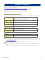
Minimum System Requirements
Windows Vista / Windows 7
Windows XP
n The system requirements described above are applied to the DME Designer version 3.8.0. Keep in mind that the software is
often updated and the system requirements are subject to change. You can check the latest version information and its system
requirements at the following website.
http://www.yamahaproaudio.com/
The system requirements may differ slightly depending on the particular computer.
n Disable any power-saving mode on the computer.
n When using the Windows Vista operating system, use only USB-MIDI Driver V3.0 or later, and DME-N Network Driver V1.2 or
later.
When using the Windows 7 operating system, use only USB-MIDI Driver V3.0.4 or later, and DME-N Network Driver V1.2.1 or
later.
Software Installation
OS Windows 7: Ultimate / Professional / Home Premium
Windows Vista: Ultimate / Business / Enterprise
Windows XP: Professional / Home Edition
Hard Disk 300MB or more
Display 1280 x 1024 pixels or higher; High Color (16-bit) or higher
Other Pointing device such as a mouse
Ethernet (100Base-TX/10Base-T) port or USB port
CPU 32bit: 1.4GHz or higher Intel Core/Pentium/Celeron family processor
64bit: Intel 64 compatible processor
Available Memory 1GB or more (2GB or more on Windows 7 64-bit)
CPU 1GHz or higher Intel Core/Pentium/Celeron family processor
Available Memory 256MB or more

Software Installation
DME Setup Manual 4
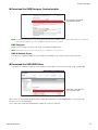
Download the DME Designer Combo Installer
n The DME-N Network Driver can be downloaded individually, but the DME Designer Combo Installer allows you to download
and install both DME Designer and the DME-N Network Driver in one operation.
DME Designer:
DME system settings can be made using this dedicated application.
n DME designer can be used in online mode even if a DME unit is not connected.
DME-N Network Driver:
This driver is needed in order for your computer and DME unit(s) to be connected via Ethernet.
Download the USB-MIDI Driver
This driver is needed in order for your computer and a DME unit to be connected using a USB cable.
When each has been downloaded, please expand it and place the expanded folder in an easy-to-find
location such as your desktop.
Then, follow the steps described below in order to install the software.
Use this link to download
the required software.
Select the correct driver for
your computer's OS.

Software Installation
DME Setup Manual 5
Install DME Designer and DME-N Network Driver
Follow the procedure outlined below to install the DME Designer application and the DME-N Network Driver
using the DME Designer Combo Installer.
1 After the downloaded compressed file is
properly extracted, double-click the
“setup.exe” file.
The setup wizard for the DME Designer Combo
Installer will be displayed.
2 Execute the installation by following the
directions appearing on the screen.
DME Designer will be installed first of all,
followed by the DME-N Network Driver.
n If a DME Designer or DME-N Network Driver version
other than the version being installed is already
present, it will be uninstalled before the new
installation begins. In this case it will be necessary
to restart the computer after the existing software
has been uninstalled. In all cases it will be
necessary to restart the computer after the new
software has been installed. Follow the on-screen
instructions.
USB-MIDI Driver Installation
1 Disconnect all USB devices from the
computer except for the mouse and
computer keyboard.
2 Start the computer and use the
“Administrator” account to log on
Windows.
Close all applications and windows that are
open.
3 Turn off the power of the DME unit.
4 Connect the USB connector of the
computer to the USB TO HOST
connector of the DME unit with a
standard USB cable.
n Do not use a USB hub for connecting multiple USB
devices.
5 Turn on the power of the DME unit(s).
6 When the “Found New Hardware Wizard”
window appears, click [Cancel].
n This screen will not appear on Windows 7. When
the message “Device driver software was not
successfully installed.” appears, continue the
installation procedure.
n On some computers, it may take a few minutes
before this screen appears.
7
After the downloaded compressed file is
properly extracted, double-click the file
“setup.exe.”
The “Preparing to install” window appears. The
next window will appear after finishing this
preparation.
n (Windows Vista/Windows 7) If the “User Account
Control” window appears, click [Continue] or [Yes].

Software Installation
DME Setup Manual 6
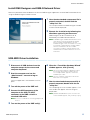
8 When the “Welcome to the InstalShield
Wizard for Yamaha USB-MIDI Driver”
window appears, click [Next].
n When the number of installed USB-MIDI drivers
exceeds the Windows OS limit (10 instances) an
error message will appear. In this case reinstall
the Yamaha USB-MIDI Driver after uninstalling any
unnecessary USB-MIDI drivers (page 28).
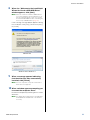
If the warning message below appears during
the installation, click [Yes], [Continue Anyway],
or [Install].
9 When a message appears indicating
that the driver has been successfully
installed, click [Finish].
n On some computers, it may take a few minutes
before this screen appears.
10 When a window appears prompting you
to restart the computer, do so.
Restart the computer by following the on-screen
directions.
n This display will not appear when using Windows
XP x64/Windows Vista/Windows 7. No restart is
necessary.
Windows XP
Windows Vista / Windows 7

DME Setup Manual 7
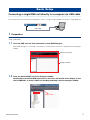
Connecting a single DME unit directly to a computer via USB cable
This section covers the most basic configuration – that is, using a single computer to control a single DME unit.
1 Preparation
Before launching DME Designer, it is critical that the DME unit is turned on and then connected to the computer
using a USB cable.
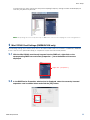
1-1 Once the DME unit has been connected, launch DME Designer.
When DME Designer is launched a new project is created and a new zone is displayed in the designer
window.
1-2 Place the desired DME unit in the designer window.
Double-click a connected DME unit shown in the list on the left side of the display (in this
case a DME24N), or select a DME unit and drag-and-drop it into the designer window.
Basic Setup
USB cable
Main Panel window
Designer window
Drag and drop

Basic Setup
DME Setup Manual 8
In response to this action, the Device Group and Sampling Frequency Settings window will be displayed.
Click the [OK] button to proceed.
n Group settings are not necessary when only one DME unit is connected. The sampling rate can be changed later on.
2 Mini-YGDAI Card Settings (DME64N/24N only)
The following settings are used only when one or more Mini-YGDAI cards are installed in a DME24N or DME64N.
If this is not the case, proceed to Step (3. Component Layout and Connection) below.
2-1 With the Mini-YGDAI card already inserted into the DME unit, right-click on the
corresponding DME icon and select [Properties…] from the bottom of the menu
displayed.
2-2 In the DME Device Properties window that is displayed, select the currently-inserted
expansion card as shown below and click the [OK] button.
Right-click [Properties...]

Basic Setup
DME Setup Manual 9
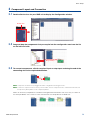
3 Component Layout and Connection
3-1
Double-click the icon for your DME unit to display the Configuration window.
3-2 Drag and drop the components that you require into the configuration area from the list
on the left-hand side.
3-3 To connect components, click the required input or output port and drag the end of the
connecting wire to the required destination.
n Components can also be freely dragged around the configuration area using the mouse.
n To remove a component or an incorrectly connected wire, click the component or wire, confirm that it turns red, and
then press the [Delete] button on the computer keyboard.
When all necessary components have been arranged and connected in the same way, as shown in
the example below, next, create a scene and transmit the setup data to the DME unit.
Double-click
Drag and drop

Basic Setup
DME Setup Manual 10
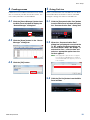
4 Creating scenes
In order to transmit all data created thus far to a DME
unit, it is necessary to store at least one scene. The
scene store procedure is outlined below.
4-1
Click the [Scene Manager] button from
the Main Panel window to display the
“Scene Manager” dialog box.
4-2 Click the [Store] button in the “Scene
Manager” dialog box.
4-3 Click the [OK] button.
5 Going On-Line
When synchronization with the DME unit has been
achieved and the connection is online, the DME
Designer settings are written to the DME unit.
5-1
Click the [Communication Port] button
from the Main Panel window to display
the “Communication Port” dialog box.
5-2 When the “Communication Port”
dialog box is displayed, ensure that the
Tx, Rx, and Device Group settings are
as shown below. When “No Assign” is
selected for Port 1, click the item and
select an appropriate option from the
list that appears.
n If the appropriate option list does not appear
even though the USB-MIDI driver is installed,
check that the DME unit is properly connected
to the computer.
5-3
Click the [On-line] button from the Main
Panel window.

Basic Setup
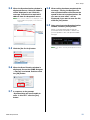
DME Setup Manual 11
5-4
When the Synchronization window is
displayed, the text “Select IP Address”
will be displayed in red. Click this
message and select the required IP
address from the drop-down menu.
n If the correct IP address is not displayed, check
that the DME unit is properly connected to the
computer.
5-5 Click the [Go On-line] button.
5-6 When the Sync Direction window is
displayed, ensure that [DME Designer
-> Device] is selected, and then click
the [OK] button.
5-7 In response to the prompt,
“Synchronizing will cause audio to
mute. Is this OK?”, click the [Yes]
button.
5-8 When writing has been completed, the
message, “Saving the Designer file
after synchronization will enhance the
speed of the next synchronization. Do
you want to save now?” will be
displayed. If you want to save the file,
click the [Yes] button.
5-9 After returning to the Synchronization
window, click the [Close] button.
When synchronization processing has
finished and the connection is online, the
[On-line] button in the main panel window
will light.
n To go offline, click the [On-line] button to turn it
off.

Basic Setup
DME Setup Manual 12
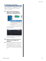
6 Checking sound output
In the case of DME24N, DME8i-C, DME4io-C, DME-
8i-ES or DME4io-ES units, appropriate HA control
settings must be made prior to checking the
system’s sound output.
6-1 Right-click the [Analog Input]
component and select [Open HA
Editor] from the drop-down menu.
An “Analog” dialog box that allows head amp
settings will appear.
By default, the gain is set to +10 dBu (i.e.,
the lowest possible gain).
6-2 Adjust the sensitivity to the correct
level for the connected audio
equipment.
n The level displayed by [Gain] is the sensitivity level to be
matched. As the sensitivity of most professional audio
equipment (using XLR connectors) is +4 dBu, the level
shown by [Gain] should be set to “4” in such a case.
When using input from microphones or other similar
sources, turn the dial clockwise to adjust the input volume
to a suitable level. Specifically, it is recommended that
the level shown by the input meter be peaking at around
-18 dB.

DME Setup Manual 13
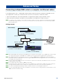
Connecting multiple DME units to a computer via Ethernet cables
In the following two cases, a USB cable should not be used to connect your computer and DME units for
actual operation; instead, you should make the necessary connections via Ethernet cables.
• Two or more DME units are to be controlled in a single device group (using a Network switch).
• When the distance between the DME unit and computer is too great for a USB connection.
n If a company or office network is to be used for this purpose, it will be necessary to switch back and forth between the DME
network and the regular network. In such a case, we recommend connection via USB or the use of a commercially-available
Ethernet/USB interface.
Setting example
n When multiple DME units are being used, the DME units are controlled in “device groups.” Since all DME units in a device group
are controlled via the group’s master DME unit, one DME unit in each group must be designated as the group master.
n When DME64N/24N units running firmware version 3.5 or earlier and DME64N/24N or DME Satellite units running firmware
versions 3.8 or later are combined in the same device group, DME64N/24N units running firmware version 3.5 or earlier cannot
be designated as the group master.
n The device group master DME unit can be connected to the computer via a USB cable. Slave DME units can be connected to
the group master via USB cables.
n Use a network switch that is capable of 100Base-TX operation.
n The maximum length of cables that can be used to connect DME units to a network switch is 100 meters. Proper operation at
this length, however, will depend on the quality of the network switch and cables used, and cannot be guaranteed.
n Use CAT5 STP (shielded twisted pair) type cable to maximize resistance to electromagnetic interference.
n If you are using multiple DME series units, set Link Mode on each unit to the same setting. Yamaha recommends that you select
100Base-TX for the Link Mode setting.
Advanced Setup
Device Group
Group Master
DME4io-C
(IP Address: 192.168.000.002)
Ethernet cable
Network Switch
Ethernet cable
DME8o-C
(IP Address: 192.168.000.003)
Ethernet cable
Ethernet cable
DME64N
(IP Address: 192.168.000.004)
Computer
(IP Address: 192.168.000.001)

Advanced Setup
DME Setup Manual 14
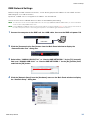
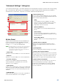
DME Network Settings
Before making the DME network connections, set the device group and IP address for each DME unit from
DME Designer via a USB connection.
By default, all DME units are assigned the IP address 192.168.000.002.
Please ensure that the USB-MIDI driver has been installed before proceeding.
n T
he same driver can be used for multiple DME units of the same type (DME64N, DME24N, DME Satellite). A common USB driver
can be used for multiple DME Satellite units.
n If using a DME64N or DME24N, setting can be performed directly via the front display (page 21). ICP1 settings can be made via
the unit’s control panel. Refer to “ICP1 settings and operation” of the DME Designer V3.8 Owner’s Manual.
1 Connect the computer to the DME unit via a USB cable, then turn the DME unit power ON.
2 Click the [Communication Port] button from the Main Panel window to display the
“Communication Port” dialog box.
3
Select either “YAMAHA USB OUT 0-1” or “Yamaha DME NETWORK-1” for the [Tx] (transmit)
field, and “YAMAHA USB IN 0-1” or “Yamaha DME NETWORK-1” for the [Rx] (receive) field,
and click the [OK] button.
4 Click the [Network Setup] from the [Hardware] menu on the Main Panel window to display
the “Network Setup” dialog box.
USB cable

Advanced Setup
DME Setup Manual 15
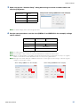
5 Make sure that the “Network Setup” dialog box settings are made as shown below, the
click the [OK] button.
n The default settings can be used for the group master.
6 Use the same procedure to set the slave (DME8o-C and DME64N in the example) settings
and IP address.
n The subnet mask is fixed at “255.255.255.0”.
n The host address can be set from 2 to 253 for the Master device, and from 3 to 253 for Slaves.
n
Always use a private address (192.168.0.2. through 192.168.255.253) unless it is absolutely necessary to use a global
address. Consult with the network administrator if it is necessary to use a global address.
n Although an error will be displayed on DME units at this time, it can be ignored. (This message is output due to group
settings not yet having been made.)
DME8o-C DME64N
Master/Slave Slave
IP Address 192.168.0.3 192.168.0.4
Master ID 192.168.0.2
Link Mode 100Base-TX
Master/Slave Master
IP Address 192.168.0.2
Master ID –
Link Mode 100Base-TX
Group master settings (DME4io-C in the example).
Slave settings (DME8o-C in the example). Slave settings (DME64N in the example).

Advanced Setup
DME Setup Manual 16
Computer Network Settings
The computer’s IP address and TCP/IP filtering must be set up to allow network communication with the DME
device(s).
Windows Vista / Windows 7
1
Select [Start]
[Control Panel], then click
or double-click [Network and Sharing
Center] or [View network status and
tasks].
The “Network and Sharing Center” is displayed.
2 Click [Manage network connection] or
[Change Adapter settings] from the
“Tasks” list located in the left side of
“Network and Sharing Center” window,
then double-click [Local Area
Connection].
The “Local Area Connection Status” dialog box
will be displayed.
n The “User Account Control” dialog box may appear.
Click [Continue] or [Yes] button.
n
If the “Local Area Connection properties” dialog box
appears, skip ahead to step 4.
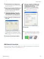
3 Click [Properties].
The “Local Area Connection properties” dialog
box will be displayed.
n The “User Account Control” dialog box may appear.
Click [Continue] or [Yes] button.
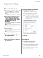
4 In the [Network] tab, choose [Internet
Protocol Version 4 (TCP/IPv4)], and click
the [Properties] button.
The “Internet Protocol Version 4 (TCP/IPv4)
Properties” dialog box will be displayed.
5 Click [Use the Following IP Address] on
the [General] tab.
6 Enter your computer’s IP address into
[IP address], the Gateway’s IP address
into [Default gateway], and
“255.255.255.0” into [Subnet mask].
n The network address must be set to that same
address as the DME devices, while the host
address must be set to a different value.
n S
et the IP address of the gateway when the gateway
exists. Set the vacant address when the gateway
does not exist. You should set the address in the
same subnet as IP address. The address should be
set in the same subnet as IP address within LAN in
which the subnet is set.
7 Click [OK].
Windows XP
1 Select [Start] [Control Panel].
The “Control Panel” is displayed.
2 If the control panel appears as category
view, click [Switch to Classic View].
3 Double-click [Network Connections]
[Local Area Connection].
The “Local Area Connection Status” dialog box
will be displayed
n If the “Local Area Connection properties” dialog
box appears, skip ahead to step 5.

Advanced Setup
DME Setup Manual 17
4
Click [Properties] on the [General] tab.
The “Local Area Connection Properties” dialog
box will be displayed.
5 Select [Internet Protocol (TCP/IP)] on the
[General] tab, then click [Properties].
The “Internet Protocol (TCP/IP) Properties”
dialog box will be displayed.
6 Click [Detailed Settings], then in the
“TCP/IP Detailed Settings” dialog box
click [Properties] in the [Options] tab.
The “TCP/IP Filtering” dialog will be displayed.
7 Select “Permit All” for TCP Ports, then
click [OK].
The display returns to the “Advanced TCP/IP
Settings” dialog. Click [OK] to return to the
“Internet Protocol (TCP/IP) Properties” dialog.
n Consult the network administrator if settings need to
be changed.
8 Click [Use the Following IP Address].
9 Enter your computer’s IP address into
[IP address], the Gateway’s IP address
into [Default gateway], and
“255.255.255.0” into [Subnet mask].
n The network address must be set to that same
address as the DME devices, while the host
address must be set to a different value.
n Set the gateway IP host address to 254.
10 Click [OK].
n If the computer is being used in an office, for example,
and already has an assigned IP address, either the
current settings will have to be changed or the computer
will have to be connected to the DME unit via a USB
cable.
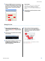
DME Network Connections
When the necessary settings have been made, connect the DME units and computer via a switching hub
using Ethernet cables, as shown in the example on page 13.
Network
Switch
Computer
DME4io-C
DME8o-C
DME64N
USB

Advanced Setup
DME Setup Manual 18
Setting the DME-N Network Driver
In order for the computer to recognize the DME device(s), it is necessary to register the IP address and device
name of the DME device that is the Device Group Master.
n Refer to page 23 for details on DME-N Network Driver setup.
1 Select [Start] [Control Panel].
The “Control Panel” will appear.
2
If the control panel appears as category
view, switch the view as follows:
For Windows XP
Click [Switch to Classic View] in the upper left
of the control panel.
For Windows Vista
Click [Classic View] in the upper left of the
control panel.
For Windows 7
Click [View by : Category] in the upper right of
the control panel, and select “Large icons” or
“Small icons”.
3 Double-click the [DME-N Network Driver]
icon.
The “DME-N Network Driver” dialog box will
appear.
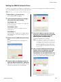
4
Click the [Advanced Settings] button to
open the “Advanced Settings” dialog box.
DME devices connected to the network can be
automatically detected via this dialog box.
5
Enter the IP address range over which you
would like to automatically detect connected
DME devices in the [Detect from] and
[Detect to] fields, and click [Start].
Automatic DME detection will begin.
n In this example the IP address of the first device is
192.168.0.2, the IP address of the second device is
196.168.0.3, and the IP address of the third device
is 192.168.0.4. In this case it is necessary to set the
last [Detect from] digit to 2 or lower, and the last
[Detect to] digit to 4 or higher. Note that setting an
excessively large detection range can result in long
detection times.
6
When automatic DME device detection has
finished, check the [Add] box of the DME
device that is to function as the Device
Group Master, and click [Add to Device List].
The “Advanced Settings” dialog box will close and
return to the “DME-N Network Driver” dialog box.
n If the IP address was not automatically detected,
register the DME device manually (page 23).

Advanced Setup
DME Setup Manual 19
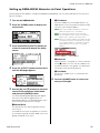
7 Select the DME unit that is to function as
the Device Group Master from the Target
Device List, enter the Device Name and
Device Port No., and click the [Apply]
button.
Device Name
Displayed as the port name in DME Designer.
Device Port No. (MIDI port number)
Set to “1.” “2” is also available for DME64N/24N
devices.
8
Click the [Save and Close] button to close
the dialog box.
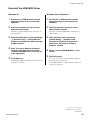
Going On-Line
1 Place and connect the required
components as described in the basic
setup procedure (page 7) beginning from
step 1-1.
2 Click the [On-line] button from the Main
Panel window.
3 Click “Select IP Address”, ensure that the
IP addresses for all devices are
displayed collectly, and then click the
[Go On-Line] button.
4 When the Sync Direction window is
displayed, ensure that [DME Designer ->
Device] is selected, and then click the
[OK] button.
Check sound output as described in the Basic
Setup section (page 12).

DME Setup Manual 20
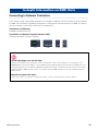
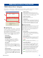
Connecting to External Controllers
ICP1, CP4SF, CP1SF, and CP4SW controllers are available as optional extras for remote external control of
the DME units. For details regarding installation of a control panel and connection to the DME unit, please
refer to the owner’s manual that came with the control panel.
Connection via Ethernet
Intelligent Control Panel ICP1
Connection via General Purpose Interface (GPI)
Control Panel CP4SF, CP1SF, or CP4SW
In-depth Information on DME Units
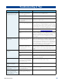
Tips
Check Input Signals via the GPI Page
Signals received at the GPI IN terminals can be monitored in real time via the Utility screen GPI page on the
DME64N/24N control panel display, or via the DME Designer Utility dialog box GPI monitor. If the DME unit is not
responding properly even though the appropriate signals are being received at the GPI IN terminals, there may be
a problem with the DME settings. If there is no problem with the DME settings there may be a problem with the
DME unit itself.
Maximum length of GPI cables
CPEV cables with a core diameter of 0.65 mm or more can be used over distances of up to 100 m.
ICP1 CP4SF CP1SF CP4SW
La pagina sta caricando ...
La pagina sta caricando ...
La pagina sta caricando ...
La pagina sta caricando ...
La pagina sta caricando ...
La pagina sta caricando ...
La pagina sta caricando ...
La pagina sta caricando ...
-
 1
1
-
 2
2
-
 3
3
-
 4
4
-
 5
5
-
 6
6
-
 7
7
-
 8
8
-
 9
9
-
 10
10
-
 11
11
-
 12
12
-
 13
13
-
 14
14
-
 15
15
-
 16
16
-
 17
17
-
 18
18
-
 19
19
-
 20
20
-
 21
21
-
 22
22
-
 23
23
-
 24
24
-
 25
25
-
 26
26
-
 27
27
-
 28
28


Yamaha DME Designer Manuale utente
- Categoria
- Software
- Tipo
- Manuale utente
in altre lingue
- English: Yamaha DME Designer User manual
- français: Yamaha DME Designer Manuel utilisateur
- español: Yamaha DME Designer Manual de usuario
- Deutsch: Yamaha DME Designer Benutzerhandbuch
- русский: Yamaha DME Designer Руководство пользователя
- Nederlands: Yamaha DME Designer Handleiding
- português: Yamaha DME Designer Manual do usuário
- dansk: Yamaha DME Designer Brugermanual
- čeština: Yamaha DME Designer Uživatelský manuál
- polski: Yamaha DME Designer Instrukcja obsługi
- svenska: Yamaha DME Designer Användarmanual
- Türkçe: Yamaha DME Designer Kullanım kılavuzu
- română: Yamaha DME Designer Manual de utilizare
Documenti correlati
-
Yamaha V3 Manuale del proprietario
-
-
Yamaha V2 Guida d'installazione
-
-
-
-
-
-
-