


TEST AND ADJUSTMENT CHECK
LIST
FOR
QGB
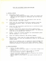
1.
General
checks
1.1 Tensi-ometer-holder
circuit:
check that
the
plastic
block-stops
(under
the tension
arm
pulteys)
are well
pressed
in
(distance:
abt lmm
from
the
ci-rcuit)
.
L.2 Check
the distance
between
the tensiometer
lever
and the
pulley
beneath : 6mm
(use
a shim).
,,
)
1.3 Check
that the
tensiometers
block-stop
contacts
touch
the
corresponding
plates,
about I
mm before
the
mechanical
block-stop.
I.4
Check
that
the tensiometer
push-hub
ball
is correctly
fixed
on
the
threaded rod.
1.5 The
fast tape-running
switch
must
switch
symmetrically,
refering
to the
corresponding
switch
movement.
The adjusting
screw
has
to be assured
with
"Loctite".
1.6 Brakes
: check
the
distance
between
the electromagnet
poles
and.
the armature
: Or3
Or4 mm.
L.7 Check
the winding
direction"
cam
sliding
freedom.
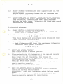
1.8
Main
circuit
: check
that
the
levers
assuring
the
circuít
rigídÍty
does
not touch
the
neighbouring
tracks
on
the
prÍnted
)
circuit
board.
Check
with
an
ohmmeter
that
no connection
exists
between
the
radiator
and
the cottector
of each
po$/er
transistor.
These
transistors
mounted
on insulators
coated
with silicon
grease.
2. Brake
adjustment
2.I
-
Unplug
the
main
circuit-
Connect
a
stabitized
power
supply
to
the
brake release
coil
terminals.
slowly
increase
the voltage
unt-il
brake
is released.
The brake release
voltage
3
v (vaet(
a V
Correct
the brake
release
voltage
by adjusting
the corres'
ponding
springs
ans
Push-nuts.
Spring
length on
both
sides of
the
brake
release
must
be
equa1.

rc
2
*
2.2
Slowly decrease
the stabÍlized
power
supply voltage ti1I
the
brake operates.
At
that moment, the voltage
between the coil terminals
must
be
lower
than 1r5 V.
2.3
Place a tape-reel
(if
possible
a large one) on the reelholder.
Attach
the
end of the tape to
a dynamometer. PulI so that
the
tape moves slowIy
(the
stabilized
power
supply unplugged.
Evaluate the brake torque : 75O
gcm/min.
The
other
brake
should
be checked. in the same v¡ay.
3. Electrical
adjustment
3.I
Supply
QGB
from a
stabilized
power
supply.
Progressively
increase the voltage up
to
25
V
(check
the
current value at
the same tiJne) .
3.2 Adjust the
10 V voltage within O,2
V
10 V
+
O,2
V
This should be done with
a resistance
placed
between the
base
of
Q32
and
ground.
Measure on
TPll.
3.3
The oscilloscope
connected to
TP2.
check
if the correct HF
sÍgnal
(the
tensiomet,er differencj-al
transformer
supply signal)
is
present.
13 v< v
p-p<
1s v
3.4 Switch
off
"Autom.
Stand,by".
Push
"Fast
Winding"
button.
The
"Loading"switch
in neutral
position.
\
'
3.5
P1ace an insulating
film between
one of the tape-end
conÈacts
and the corresponding
tensiometer
p1ate.
Move forward the
left tensiometer,
then
release
it.
The
QGB
should
start
(it
is important
to
hear a slight click
produced
by the
brake release).
The
right
motor starts turning.
The
left motor remains
stationary
if the
"moving
direction"
cam.
is operating correctly.
The
"rotatíng
indicator" turns
white.
3.6
Move
the
"Loading"
swj-tch
on the right.
This should
simultaneously
suppress the
"winding
direction"
cam
action and stop
the right
motor.
Consequently,
right
motor should.
stop and
the left one
should
start.
The
rot.ating
indicator turns
black, to indicaÈe
that
this
function
cannot
be employed
for normal
running.

i)
*3:t
Move
the
"Loading"
switch
on the 1eft.
The
"rotating
j-ndicator"
stays bIack.
The
left
motor
stops, the
right one starts to turn
again.
Replace
the
"Load.ing"
switch in
neutral
position.
3.7
Check
of the
"Fast
Winding" knob
action.
Pull up
the
"FasÈ
Winding" knob.
The
rotat,ing indicator"
turns
black once more for the same
reason
as before.
This time,
both
motors should rotate, because the
"Fast
Vtinding" knob
suppresses the cam action.
Push
down the
"Fast
Winding"
button again.
3.8
Check of
the
"rotation
detector" and of the correct operation
of the bistable
"ON-OFF"
locking system.
Switch on the
"Autom.
Standby".
After
Ir5 to
3 sec., the brakes operate and the
QGB
stops.
3.9 The
"Autom.
Standby
remains swj-tched on.
Press
"Load.ing"
switch
to
the left,
then
immediately
to
the
right.
The
system starts again but
does not stop after 1r5
to 3
sec.
as the
"rotating
detector" receives a
"rotation
signal" from
the left
reel-holder.
Manually
stop
the
left motor,
checking aÈ the same time the
supply current which should not be
(
0,65 A.
1r5 to 3 sec. after
complete
motor
stop, the brakes operate
and the
QGB
stops.
This test should be
performed
to ensure rotating detector
immunity from interference from
the
left motor
when the
motor
is mechanicaly blocked.
3.1O
Switch
off the
"Autom.
Standby"
Switch
on the
QGB
with the left tensiometer.
Decrease the
power
supply voltage
till the
"rotating
indicator"
turns black
ro,7 v-( v suppry¡(
1r,3
v
(the
rotating indicator should show
that
this voltage Ís
too
1ow for a normal running).
3.11 Switch
on the main
power
supply
z
25
\Ì.
The-"Loading" switch is
in
neutral
position.
The
"Fast
Winding" button
is
pushed
down.
Remove the left motor belts and switch on
the
QGB.
Check the volÈage between
10 V lines and the
"Winding
direction" detector output
(red-blue
wire).
Turn anti-clockwise the left reel-holder to
displace the cam
up to
the block-stop.
Adjust then the
potentiometer
on
"Winding
direction" circuit
in order to
obtain O,4 V
(approxJ-mate1y,
the voltage
is near
the one necessary to
open the base-collector
junctÍon).
Turn
the reel-holder up to the cam
opposite block-stop.
The
corresponding
voltage
should range
between 116 V and
2,2 V.
This test
allows the check
of
the voltage
progression
which
Ís
dependant on the
cam rotation
angle
(a
too
fast
progression

lt
*4*
could
create
an
oscillatory
phenomenon).
Perform
the
following
test
: move
the cam to the
left block-
stop
(corresponding
to
Or4 V), The
left motor
turns
at
maximum
speed. Turn
now
the reel-holder
to
the right
ti1l
the
motor
stops.
The
rotation
angle of
the reel-hold.er
should
range between
18O
o
and 27Oo.
Test
objective
: on one
side, it is
necessary
to conserve a
reserve
for
cam angular
movement,
indispensable
to lock the
motor.
on the
other
side,
if the
reserve is
too
great,
it
means
that there
is a
defect in
the
"moving
dj-rection"
d.etector and
the system
could
became instable.
3.I2
Switch on the
QGB
and
switch
"Loading"
to
the right
(the
left
motor turns).
Move
the left
tensiometer
and check
that the
transi-tion from
maximum
to zeto
torque
of the motor is
located
between the
tensiometer
block-stops,
about
lOo around
the central
position.
Replace
the
"Loadj-ng"
switch
in neutral
position.
Same test
must be
performed
on the right
tensiometer.
3.13 The
right. motor
turns.
Move
the
"Windj-ng
directÍon" cam
clockwise to
the block-stop.
Switch
"Loading"
to the left,.
Move
the
right tensiometer
in order to
stop the
right motor.
Replace
then
"Loading"
in neutral
positi-on
:
the right motor
should turn.
This test
permits
the
check
of
the servo-system
on
the right
motor
(same
test
of the left
motor was checked
under
pt
3.11).
3.14 The
QGB
starts : if
the
"Fast
Winding" button
is
pulled
up,
if
the left
tensiometer is moved
forward,
if
the tensiometer
is
pulled
up
and
touches
"taut-tape"
block-stop.
3.15
Swj-tch
"Loading"
to the
right. The left
motor
turns.
Manually
slow down the left
reel-ho1der.
PuII
up
"Fast
Winding" button. The
reel-holder
torque should
decrease
during about Or5
sec. and immediately
after should
return to its
normal
va1ue.
Switch
"Loading"
to the
left and.
perform
the
same test on the
other motor.
The
temporary
torque decrease
is necessary,
because
the
"Fast
Winding"
switch suppresses
abruptly the
"winding
direction"
cam effect
which could induce
a violent
shock to the tape.

3 .16
3
.17
3
.18
)
3.19
*5*
When
"Autom.-Standby"
is switched
on
and
the brakes
operate
(after
1r5 to
3 sec.) the
motors should
still be
powered
during I to 2
sec.
otherwise the tape
would unwind.. This fact
could
be
checked by
removing the belts
and by manual slowing
down the
motors after
switching
on
QGB
and
"Autom.Standby".
Switch off
"Loading"
and
"Autom.Standby".
Switch
on
"QGB"
and
push
to the
"taut
tape" block-stops
the
2
tensiometers.
l"love
"Fast
Winding" to neutral
position
and
pu11
it
up. On
the
first
stage, nothing
should happen. Moving
the swit,ch
rrFw'r
to
the left
then to
Èhe right, each time it
provokes
the corres-
ponding
motor
start
(left
or
right).
This
test is
performed
to
check
if
the
rrFW,
action
cancels
completely
at a specific moment and with
restriction the
tensiometer
action.
Remove
the insulating film
placed
between the tape end contact
and the tensiometer
plate.
Switch
on the
QGB
and let the tensiometers
touch the
2
tape
end contacts.
At the
same
time,
control
-1O
V
stab. voltage. This
voltage
must subsist for 2
Eo 3 sec.,
after
the tensiometers both
touch the contacts.
The
voltage
then drops,
brakes
operate and everything
stops.
Reason
for the delay : sometimes,
during
a short
period
of
tlme, both tensiometers touch sÍmultaneously
wiÈh tape end
contacts.
It is important that, ât that time,
the brakes do
not
operate
causing the
QGB
to
stop
and
possibly
damage
the tape.
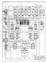
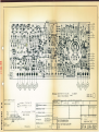
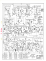
Check on
the oscilloscope TPI, TP3, TPA, TP7
and
TP8
points.
Check that the
traces
correspond.
to those
given
on the dia-
gram.
Respect measure conditions
given
on the d.ì-agram. For
a
"trian-
gular
signal" voltage,
lower
and higher
limit must
range
between
-4,5
V
and.
-8r3
V and
the magnitude
between
-2t6
Vl
and
-3,4
V
peak
to
peak.
Chejck
'9
V
voltage
:
8,9 to 9,1 V range.
Check
that
the
voltage
variation when
the tensiometers
move
from
one
block-stop to the
other
(without
touching them) is
ínferior
to O,3 V max.

4.
4.L
6-
Test
with
QGB
fixed to NAGRA
Place
a
lOr5rr
full reel
on
the left
reel-holder.
Tape
running with the smaI1 reel
(5")
on the right reel-
holder. Ad.just
the
potentiometer,
corresponding to the
left
tensiometer
(on
the tensiometer circuit) in order
that
it is
placed
at about
6
mm
from the tape-end mechanical
block-stop
(at
about 5 mm
from the electrical block-stop).
Rewind
completely
the
tape on the left
reel.
Fix the tape-end to a
dynamometer,
pass
the
tape around
the
QGB
tensiometer and
NAGRA left tensiometer.
Then adjust
the
tensiometer
spring in order to
have 55
t
2
gr.
on
the tape.
During adjustment :
-
switch
off the
"Autom.
Standby"
(unit
is swj-tched on)
push
the
"Loading"
switch to the
right
(1eft
moÈor is
powered)
If necessary, repeat the
potentiometer
adjustment during
normal
running
and finally
adjust
the spring.
Normal tape running : adjust the
potentiometer
corresponding
to the right tensiometer
in
order
that the tensiometer is
positioned
half-way
between the
2
extreme
block-stops
(when
employing
a 5rr reel, almost empty,
it will be
placed
somewhat nearer
to
"taut
tape
"
block-stop).
Adjustment
of the right tensiometer
spring : ro11 up
t to
2 mm
of
tape on the
5r'right reel. The capstan
is
completely
free
For
a
certaj-n right spring tension,
the tape runs from
the
left
1Or5" full reel to the small,
nearly
empty,
right
reel.
Adjust
the
right
spring tension
in
order
that the tape
stops.
"Reliever"
resistance determination.
Separate
the left tensiometer
contact from the corresponding
tape end contact.
Distance to be kept between these
2
contacts
:
2 mm.
Pull up the
"Fast
Winding"
button and turn
it
anti-clockwise
(FWD)
up to
the block-stop
(adjustment
wi-thout tape) .
Place
a resistance
(ranging
beÈween
39o K.lLand
1Mn-) in
the
place
foreseen for the
"reliever".
The left motor should stop
turning at
a certain resistance
value.
Thè resistance should be
adjusted in order to
stop the motor
running.
\
4.2
4.3
If
the
resistance value is rated
between two E 12
standardized
values,
chose the highest value.
4.4
Stability
control of the servo
system :
normaf
tape
running
tap
lightly on the tensiometers
in direction of Nagra.
the tensiometers
return
quickly
in the stable state.
Perform these tests with a
10,5" nearly full reel on
the
left,
and a 5" nearly empty reel
on the right.
Supply with a
30 V
power
source.

r'-\
)
7-
Perform
a stability
test
on each
of
the
3 speeds.
Now
supply
with
12 V
power
source
and
perform
again
these
tests.
Interchange
the
reels
and
perform
the same
tests.
Do
not
forget
to
tighten
the
reel
nuts.
4.5
Supp1y
with 15
V.
Load
lo,5rr
reels
(one
nearly
empty,
the
other
nearly
fulr).
Control
that,
in
the
fast
running
mode,
the
full
reel
starts
turning
the
almost
empty
reel.
rnterchange
the reels
and
perform
the test
once
again.
4.6
Adjust
the
stabilized power
supply
to 30 V.
wind
on a 5r'
reel
the tape
untíI lr5 mm
thick
(on
the
left
or
right
reel holder).
The
second
reel
will
be
7,, nearly
full.
Operate
a fast
wind
in the
direction
of
the full
ree1.
when the
nearly
empty
supply
reel
reaches
a high
speed,
press
the
rlFwt'
button
in
order to
stop
the fast
tape
running.
Perform
this test
twice.
Then,
interchange
the
reels
and.
perform
sarne test
twice again.
When the
supply
reel
(the
5"
onernearly
empty)
is
on the
left
reel holder,
the
test must
be
performed
with
the
"Autom.
Standby"
switched
on.
Aim
of
this
test
:
a)
When the
small
reel is
pulled
by
the large
one,
overvoltages
are
created
that
could. reach
14O
V between
the
control
transistor
terminals
of
the corresponding
motor.
This
transistor
must
accept
the
corresponding
peaks.
b)
The
small supply
reel
beÍng
loaded
on the left,
the
"Autom.
Standby"
switched
orrr
the
correct
running function
is
ensured
only
if
Èhe
photo-transistor
(in
the
rotating
detector)
reacts
properly
to the relatively
high
interrup-
tion frequency
on the
infrared
beam.
If not,
the
brakes
should block
during the
runninq.
4.7
Keep
on the 30 V
power
supply.
Control
subjectively
the
fast
runnj-ng with
the
biggest
and
the
smallest
ree1s.
No instability
and
no
jerking
should be
noted
on the
tensiometers.
4.8
Control
the
QGB
running
with the
internal
NAGRA
power
supply.
4.9
Load
a 5" nearly
empty reeL
on
the left
reel
holder.
Run
the
tape with
the
3 speeds.
Control
if
there
is any
jerking
on the
left reel
holder.
The
tensiometer
should never
touch
"
taut
tape"
contact. Minimum
distance
between
contacts
should be equal
to 2 mm.

8-
To
check the security margin, switch
"Loading"
to the left
:
the
tensiometer
must
go
to
the
"tape
end" block-stop.
If the conditions are not
respected,
it
will
be necessary
to
control the left reel holder
(wind.ing
directj-on
cam,
ball
bearing a.s.o.
).
The
sa¡ne check must be
perf
ormed with the
right reel ho1d.er.
But it is sufficient
to
load with
a
small nearly empty
reel
on this
reel-hold.er
and.
control
that there
j-s
a regular rota-
tion and that the right tensiometer does not move.
4.1O Load 2 metallj-c 1Or5"
reels
(left
one nearly full, right
one
nearly
empty).
Supply with a
25
V
power
and let the tape run at 15rr/s.
Measure the
consumption
(of
QGB
only) : I
<
2OO mA.
Interchange the
2
reels and
perform
again the test.
Note, that
povrer
consumption
mainly depends on
tensiometer
spring tension.
4.11
Supply
with 25 v.
Measure
complete
rewinding time
(from
right to left) :
t<
4
min.
Use the 1O,5r' metallic
reel containing
11OO m. of
tape.
4.I2
Wow
tests:
Use same
reels as for tesÈ
nr. 4.I1.
Tape type 3M
20
Measure wow
with a Nagra
in
perf
ect cond
j-t j-on.
Tolerances :
at I5t
t
/s.
: OrO88
max. on
VFM
at 33/4"/s.
z O,2E
"
rr
at
Lr5"/s
: Or3Z
"
rr
,,)

-r0v
l-
LEFT
REEL
HUB
FRICTION
CLUTCH
CAM
sEl.tsE
DISCRIMI.
NAÏOR
:9V
-OV
-Unres. -tov
-9V -lOV
WHEEL
BRAKE
I
COIL
RreHT
MOTOR
AMPIFTER
FAST
WINDING
-
Unreg.
POWER
INPUT
BRAKE
69¡¡
RIG}IT
REEL
xuorrsx'
i)",,: ¡aGRÀ
c',1 sr ar^
-l
CH
l0 I'
Sw't¿"¡ld,rd l.l.¡
¿¡ J9?
|
NAGR^ xacNr rrc
RtcoRorRs tNC
I
¡¡tl \1.?¿l
-
New
Yorh
N Y
lmlö
-10v
I
xuoÈLãir
09.1¿.001 0.00

t
=tt
ä
t¡¡
'{
<
a
a
Y
U'
J
UJ
o
Ð
Y
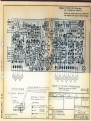
Remqrque:
Assembler
les circuits
dons
[o f iche
médiqne.
un
goborit
Valable
pour
al
crrcutt
tndice
V
Canon isolant
UF lJlA
otdtsseur
01
14
034
102
er
parattète
au
l
rc
u rt
Qq
-I
.l
:
I
s
[]¡gne
qF
]
o-3
q
s830 220
0m
=
'o
c
Redesstné
schettø'
Penuméro!é
It
q<
h'lâ F llannpr
lzy¿rsá
potonle
__ c7
2i 2s
t0
79
tY
Apule
ponl
sur
0l0e
3l zstt'rgn
4
outé bobtD¿ce
'sur
7l
J
ql
2o
tz
zg
sl
6l
co<,,:
t_i t ll lll-l
t-_l_L-l
M
al
I
er..
O ¡mer, s
Ouantifé
pr
100p
:
Irailement des surfaces
: Observalions:
Cotation
sans tolérances
Cotes
Tro us
Echelle
2:1
Dessiné 26 10
78
lWençr
controré
i I
l-am
pièces
Ptqn d'imptontotion
Circuit
principol
gouche
OGB
Atpho
num
I
A5
Còte
cuivre
cöté
cu ivre
I
n¡"",
rz,lll-

Remorque:
Les
trorsistors
e38
et
Oæ
smf
prévus
ovec
un
broclnge
style
I
boîtier
n_03
Retouner
les
tronsistors
pour
te
style
3
bdtþr 7?-og
ovec
lhdjonctim
d'une
ploque
de
t¡qrsfert
de
chcüer¡r.
-9v
-UNREG I
-
-ñ-ñ
-ü
,1
(,
I
I
-rov
@
00
E
oo
I
(J
+
UNREG
Mica
\
Canon
isotant
s830
221
001
N
(v)
l-
tn
Vis M2,5x10
038-039
Ecrou
còte
eléments
Vis
M2,5x6
025
Ecrou
côtó
soudures
]q
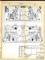
Le
contqct
femette
no. 2
ne
doit
pqs
être
monté
2e
Assembler
les
circuits
ovec
un
goborit
Vatable
pour
dqns
to
fiche
mediqne
crrcurr
¡ndrce
Remqrques
:
a
tt,
Ë
a
J
l¿J
o
Ð
Y
02s DF103B
s830
220000
b/Jö
-
UJV
5öJU 1
I5
UUU
2x
silícone
r
Rondelle
t
bombé
dessus
Ref roid
isseur
01 1/+
Monter
paraltète
au
Côté étéments
..-_
03s
102
circuit
{2
Aloule
ponls
CR
lo
e¡
n53
.R57
2
x
?p-/é
þobtn¿Qe
'sqr
TZ
Matière;
Quarrtitó
Fr
l00p:
Tra¡tement
des
surfaces :
Observations:
Coiation
sans
tolérances
Cotes
I Trous
Q
Corrtact
f enrelle
01.01.100.102
-
Pylôrre
01
04190
105
0l
04.190'106
Rivet
Dessiné
|
27.10.78
lWenger
Fanr
orèces
Ptqn d'imñltqtion
Circuit
principol
droite
GGB
025 DF
1374,/

¡
(t,
T
o
J
tr¡
o
Ð
Y
**
DROI ÏE
Vue
côtÉ
elpmpnls
oAu(- Ht
CTAUCHE
Vue côté sot¡dures
DROITE
Valable
pour
crrcurl
rnd¡ce
@
CODE
COULEURS
Btl(
r
Noir
ffi
RED
=
Rouge
@
YEL
=
Jaune
GRN
=
Vert
H
VIO
=
Violet
GRY
=
Gris
ffi
SCI.JDER SIJR
LE
CIrcUT
(ax)
=å-æ
f;=lS
^^
:i+:
i:
iir':=
\J ¡.Õ- .
code
,
[-T-l-l_l l-I-f-l
t-t-f-l
Matière;
Dimens:
Quantité
pr
100p :
Traitement des
surfaces:
Cotation sans
lolérances
Cotes
I
Trous
31
10 78
lWerçer
Plqn
d'implontotion-
Tensiomètres
GGB

-9V
-t0v
I
,r"toTr]J
I
{t
o5
Ef, TENWETER
rromgrs
I
__
I
I
t_
t€NstoraEtER
avÈtFlÊR
22
ur
¿ TT5
b Bmke @il
Mn
aart *aa m
ro
Qrs
ro
Qrr
"^i
IYP ffiRE}fI ORAIN
MnMA
il0.M,2æ ñA
FAST
SD¡RI{D
:
SnA
-u¡REO -ilY tO-ÐV
lffi
R5
6€l
BCI
$PF
tf,a)1E
anz
ñT
tP
9
ri
VOLÍAE HWEEi
I)
-q6v
@rrroloRHx
-arv
o¡tÆlHxrx
WITH CN A1
-fv
lo -sv
IYPICAL
DRÄN
ÌúRUL FWo.RWO: ämA
FÂl ilO. tro
:
Om^
TPs*l TP6*
UIAÊ€ ËIWEEÌ
-
¡v6
r r'þloR ¡¡Ð(.
-
a vo I rctoR MrN
I
WÍH TENSffiTEË
AI
EXÎEHE LIMIÎSI
---L,t--
LoÆr*o ilo Fñ
i
i i
c28
.
3€lF
R99
r0t
Rt0
rrom
@rs
Oou
BRAÍE
OflML
^ro
llf8E
CURRENT t ts EllHER srJpÞUED oR aBsoR*D tr
THE -9v
pogER
SuPFtY, ACmorNG rO 1HE l04ENfrnY
SfArE Or THE ERAKE
ffROL AND THE
sEFrc -
ÂYPLIFIER.
NOÌE:
gGNÀL
MEASURTNG CofiolltoNs FoR TP3,4,t,8:
UNREGILAIEo SUPPLY YoLTÂGE
'
ã)V
lHE I.þTOR Cü{CENNEO
.IS
MECHANICALLY STOPPEO ANO fHE
COR-
RESPONDING IENSIOT¡ETER IN SUCH A
POSITION A5
TO
CÂUSE A
ToTAL
CURRENT mÀN 0F
BEIWEEi{
250 ANo TþnA,
fHE
OÎHER M{'TOR REMAINS
FREELY
RUNNING,
j
SIMBoLS
ùd COlilVENllOÌlS
i{EA9JRING
INIRUTÆNÎ OC
VI'II€TRE
D
MII
ÁtI l¡lÊÀslnEMEt{fü
MAOÊ WITH RESP€CÌ
T0 .
GROI,NO REGIJLAÎEO
YOLIAOES
I.låY VARY
!
þ*
UTLESS
OIHERWISE
SPECIFIEO:
att RÊs{sroRs
ÀILEN
gRAoLEy
l/4tv
ttof
aLL CAåCi'OnS
:
æ*
ALL DIOÐES
IN 4I¿6
aLL lRANgloñS
NFN 8C t84
i
prp:
BC 2t4
coirNEcloRs s¡towN FRöl
(lÍslE
¡l¡
oFRÂHE(CilSslli)
OOINECIIO{S
V
.
ffiqJþ
rìRÊuLAtEo
V
.
CRdID FROi4
VOlfÂGE RÊGIJLÄIED
- -
-",**-..r;
ffi.-
-
-I
FASI WIXOIM)
lIXE
DELAY
()
c)
.l¡
r¡-)
õJ
@
crt
æ
-
UNREG
I
I
l.o
|
't'
I
I
ct9
lF
-30
-20
sEm
lmwR
ff scilÂl
9o'
iú
ÞÞ
ET
äÊ
*!
È
F
2
6n
kà
lr
õl
çÞ
ET
fÈ
õr
YûJt
Raiarm
to
TP
3,
6,9,ß,n
r)
vrrH - Ev PnEsENl
2' V{t1H
-
9V PRESEXI.
3
)
lvfl H
-
ueÉ
PRESE}{I ll.rRtNG
-
0,s c
AT
SWIICH - O}¡ OF IHE RAI(ES
OR
wnH 1Êr6¡oMErER
t¡t't
pE
Too
1tGH1'FOgTtolt.
-t
l-- $*cl---
'
V, äËËt
\-/
*'
To Bllk coll
M¡
iuDEtsxt a^
hr
w&
q-t6dEgux
@uÆrcñ@iÈñm
w 6( xY roq
iaH{úh
AltoE
Q
G B
los
t¿ oo2ooc
4979
LARGE
REEL ADAPTER
FOR NAGRA
tV tV-S tv-s.'
4.2
re-
-
 1
1
-
 2
2
-
 3
3
-
 4
4
-
 5
5
-
 6
6
-
 7
7
-
 8
8
-
 9
9
-
 10
10
-
 11
11
-
 12
12
-
 13
13
-
 14
14
-
 15
15


in altre lingue
- English: Nagra QGB User manual
Altri documenti
-
Maserati Bora (Italian - English) Manuale del proprietario
-
Tascam BR-20 Series Operation & Maintenance Manual
-
Ferrari Mondial Quattrovalvole Manuale del proprietario
-
Fostex G16S-G24S Manuale del proprietario
-
-
-
-
-