
ISTRUZIONI PER L’USO - NORME DI INSTALLAZIONE
INSTRUCTIONS FOR USE - DIRECTIONS FOR INSTALLATION
INSTRUCTIONS - REGLES D’INSTALLATION
INSTRUCCIONES PARA EL USO - NORMAS PARA LA INSTALACION
GEBRAUCHSANLEITUNG - ANWEISUNGEN ZUR INSTALLATION
GEBRUIKSAANWIJZINGEN – INSTALLATIEVOORSCHRIFTEN
SPRINT 04SPRINT 04
SPRINT 04SPRINT 04
SPRINT 04
24V / 115V24V / 115V
24V / 115V24V / 115V
24V / 115V
SPRINT 03SPRINT 03
SPRINT 03SPRINT 03
SPRINT 03
24V / 230V24V / 230V
24V / 230V24V / 230V
24V / 230V
SPRINT 03SPRINT 03
SPRINT 03SPRINT 03
SPRINT 03
24V / 230V24V / 230V
24V / 230V24V / 230V
24V / 230V
SPRINT 04SPRINT 04
SPRINT 04SPRINT 04
SPRINT 04
24V / 115V24V / 115V
24V / 115V24V / 115V
24V / 115V

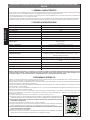
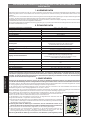
AVVERTENZE PER L’INSTALLATORE
OBBLIGHI GENERALI PER LA SICUREZZA
1) ATTENZIONE! È importante per la sicurezza delle persone seguire attentamente tutta l’istruzione. Una
errata installazione o un errato uso del prodotto può portare a gravi danni alle persone.
2) Leggere attentamente le istruzioni prima di iniziare l’installazione del prodotto.
3) I materiali dell’imballaggio (plastica, polistirolo, ecc.) non devono essere lasciati alla portata dei
bambini in quanto potenziali fonti di pericolo.
4) Conservare le istruzioni per riferimenti futuri.
5) Questo prodotto è stato progettato e costruito esclusivamente per l’utilizzo indicato in questa
documentazione. Qualsiasi altro utilizzo non espressamente indicato potrebbe pregiudicare l’inte-
grità del prodotto e/o rappresentare fonte di pericolo.
6) GENIUS declina qualsiasi responsabilità derivata dall’uso improprio o diverso da quello per cui
l’automatismo è destinato.
7) Non installare l’apparecchio in atmosfera esplosiva: la presenza di gas o fumi infiammabili costituisce
un grave pericolo per la sicurezza.
8) Gli elementi costruttivi meccanici devono essere in accordo con quanto stabilito dalle Norme EN
12604 e EN 12605.
Per i Paesi extra-CEE, oltre ai riferimenti normativi nazionali, per ottenere un livello di sicurezza adeguato,
devono essere seguite le Norme sopra riportate.
9) GENIUS non è responsabile dell’inosservanza della Buona Tecnica nella costruzione delle chiusure da
motorizzare, nonché delle deformazioni che dovessero intervenire nell’utilizzo.
10) L’installazione deve essere effettuata nell’osservanza delle Norme EN 12453 e EN 12445. Il livello
di sicurezza dell’automazione deve essere C+D.
11) Prima di effettuare qualsiasi intervento sull’impianto, togliere l’alimentazione elettrica e scollegare
le batterie.
12) Prevedere sulla rete di alimentazione dell’automazione un interruttore onnipolare con distanza
d’apertura dei contatti uguale o superiore a 3 mm. È consigliabile l’uso di un magnetotermico da
6A con interruzione onnipolare.
13) Verificare che a monte dell’impianto vi sia un interruttore differenziale con soglia da 0,03 A.
14) Verificare che l’impianto di terra sia realizzato a regola d’arte e collegarvi le parti metalliche della
chiusura.
15) L’automazione dispone di una sicurezza intrinseca antischiacciamento costituita da un controllo
di coppia. E' comunque necessario verificarne la sogli di intervento secondo quanto previsto dalle
Norme indicate al punto 10.
16) I dispositivi di sicurezza (norma EN 12978) permettono di proteggere eventuali aree di pericolo da
Rischi meccanici di movimento, come ad Es. schiacciamento, convogliamento, cesoiamento.
17) Per ogni impianto è consigliato l’utilizzo di almeno una segnalazione luminosa nonché di un cartello
di segnalazione fissato adeguatamente sulla struttura dell’infisso, oltre ai dispositivi citati al punto
“16”.
18) GENIUS declina ogni responsabilità ai fini della sicurezza e del buon funzionamento dell’automazione,
in caso vengano utilizzati componenti dell’impianto non di produzione GENIUS.
19) Per la manutenzione utilizzare esclusivamente parti originali GENIUS.
20) Non eseguire alcuna modifica sui componenti facenti parte del sistema d’automazione.
21) L’installatore deve fornire tutte le informazioni relative al funzionamento manuale del sistema in
caso di emergenza e consegnare all’Utente utilizzatore dell’impianto il libretto d’avvertenze
allegato al prodotto.
22) Non permettere ai bambini o persone di sostare nelle vicinanze del prodotto durante il funziona-
mento.
23) Tenere fuori dalla portata dei bambini radiocomandi o qualsiasi altro datore di impulso, per evitare
che l’automazione possa essere azionata involontariamente.
24) Il transito tra le ante deve avvenire solo a cancello completamente aperto.
25) L’Utente utilizzatore deve astenersi da qualsiasi tentativo di riparazione o d’intervento diretto e
rivolgersi solo a personale qualificato.
26) Tutto quello che non è previsto espressamente in queste istruzioni non è permesso
IMPORTANT NOTICE FOR THE INSTALLER
GENERAL SAFETY REGULATIONS
1) ATTENTION! To ensure the safety of people, it is important that you read all the following instructions.
Incorrect installation or incorrect use of the product could cause serious harm to people.
2) Carefully read the instructions before beginning to install the product.
3) Do not leave packing materials (plastic, polystyrene, etc.) within reach of children as such materials
are potential sources of danger.
4) Store these instructions for future reference.
5) This product was designed and built strictly for the use indicated in this documentation. Any other
use, not expressly indicated here, could compromise the good condition/operation of the product
and/or be a source of danger.
6) GENIUS declines all liability caused by improper use or use other than that for which the automated
system was intended.
7) Do not install the equipment in an explosive atmosphere: the presence of inflammable gas or fumes
is a serious danger to safety.
8) The mechanical parts must conform to the provisions of Standards EN 12604 and EN 12605.
For non-EU countries, to obtain an adequate level of safety, the Standards mentioned above must be
observed, in addition to national legal regulations.
9) GENIUS is not responsible for failure to observe Good Technique in the construction of the closing
elements to be motorised, or for any deformation that may occur during use.
10) The installation must conform to Standards EN 12453 and EN 12445. The safety level of the
automated system must be C+D.
11) Before attempting any job on the system, cut out electrical power and disconnect the batteries.
12) The mains power supply of the automated system must be fitted with an all-pole switch with contact
opening distance of 3mm or greater. Use of a 6A thermal breaker with all-pole circuit break is
recommended.
13) Make sure that a differential switch with threshold of 0.03 A is fitted upstream of the system.
14) Make sure that the earthing system is perfectly constructed, and connect metal parts of the means
of the closure to it.
15) The automated system is supplied with an intrinsic anti-crushing safety device consisting of a torque
control. Nevertheless, its tripping threshold must be checked as specified in the Standards indicated
at point 10.
16) The safety devices (EN 12978 standard) protect any danger areas against mechanical movement
Risks, such as crushing, dragging, and shearing.
17) Use of at least one indicator-light is recommended for every system, as well as a warning sign
adequately secured to the frame structure, in addition to the devices mentioned at point “16”.
CONSIGNES POUR L'INSTALLATEUR
RÈGLES DE SÉCURITÉ
1) ATTENTION! Il est important, pour la sécurité des personnes, de suivre à la lettre toutes les instructions.
Une installation erronée ou un usage erroné du produit peut entraîner de graves conséquences pour
les personnes.
2) Lire attentivement les instructions avant d'installer le produit.
3) Les matériaux d'emballage (matière plastique, polystyrène, etc.) ne doivent pas être laissés à la portée
des enfants car ils constituent des sources potentielles de danger.
4) Conserver les instructions pour les références futures.
5) Ce produit a été conçu et construit exclusivement pour l'usage indiqué dans cette documentation.
Toute autre utilisation non expressément indiquée pourrait compromettre l'intégrité du produit et/
ou représenter une source de danger.
6) GENIUS décline toute responsabilité qui dériverait d'usage impropre ou différent de celui auquel
l'automatisme est destiné.
7) Ne pas installer l'appareil dans une atmosphère explosive: la présence de gaz ou de fumées
inflammables constitue un grave danger pour la sécurité.
8) Les composants mécaniques doivent répondre aux prescriptions des Normes EN 12604 et EN 12605.
Pour les Pays extra-CEE, l'obtention d'un niveau de sécurité approprié exige non seulement le respect
des normes nationales, mais également le respect des Normes susmentionnées.
9) GENIUS n'est pas responsable du non-respect de la Bonne Technique dans la construction des
fermetures à motoriser, ni des déformations qui pourraient intervenir lors de l'utilisation.
10) L'installation doit être effectuée conformément aux Normes EN 12453 et EN 12445. Le niveau de
sécurité de l'automatisme doit être C+D.
11) Couper l'alimentation électrique et déconnecter la batterie avant toute intervention sur l'installation.
12) Prévoir, sur le secteur d'alimentation de l'automatisme, un interrupteur omnipolaire avec une
distance d'ouverture des contacts égale ou supérieure à 3 mm. On recommande d'utiliser un
magnétothermique de 6A avec interruption omnipolaire.
13) Vérifier qu'il y ait, en amont de l'installation, un interrupteur différentiel avec un seuil de 0,03 A.
14) Vérifier que la mise à terre est réalisée selon les règles de l'art et y connecter les pièces métalliques
de la fermeture.
15) L'automatisme dispose d'une sécurité intrinsèque anti-écrasement, formée d'un contrôle du
couple. Il est toutefois nécessaire d'en vérifier le seuil d'intervention suivant les prescriptions des
Normes indiquées au point 10.
16) Les dispositifs de sécurité (norme EN 12978) permettent de protéger des zones éventuellement
dangereuses contre les Risques mécaniques du mouvement, comme l'écrasement, l'acheminement,
le cisaillement.
17) On recommande que toute installation soit doté au moins d'une signalisation lumineuse, d'un
panneau de signalisation fixé, de manière appropriée, sur la structure de la fermeture, ainsi que des
dispositifs cités au point “16”.
18) GENIUS décline toute responsabilité quant à la sécurité et au bon fonctionnement de l'automatisme
si les composants utilisés dans l'installation n'appartiennent pas à la production GENIUS.
19) Utiliser exclusivement, pour l'entretien, des pièces GENIUS originales.
20) Ne jamais modifier les composants faisant partie du système d'automatisme.
21) L'installateur doit fournir toutes les informations relatives au fonctionnement manuel du système
en cas d'urgence et remettre à l'Usager qui utilise l'installation les "Instructions pour l'Usager" fournies
avec le produit.
22) Interdire aux enfants ou aux tiers de stationner près du produit durant le fonctionnement.
23) Eloigner de la portée des enfants les radiocommandes ou tout autre générateur d'impulsions, pour
éviter tout actionnement involontaire de l'automatisme.
24) Le transit entre les vantaux ne doit avoir lieu que lorsque le portail est complètement ouvert.
25) L'Usager qui utilise l'installation doit éviter toute tentative de réparation ou d'intervention directe
et s'adresser uniquement à un personnel qualifié.
26) Tout ce qui n'est pas prévu expressément dans ces instructions est interdit.
18) GENIUS declines all liability as concerns safety and efficient operation of the automated system,
if system components not produced by GENIUS are used.
19) For maintenance, strictly use original parts by GENIUS.
20) Do not in any way modify the components of the automated system.
21) The installer shall supply all information concerning manual operation of the system in case of an
emergency, and shall hand over to the user the warnings handbook supplied with the product.
22) Do not allow children or adults to stay near the product while it is operating.
23) Keep remote controls or other pulse generators away from children, to prevent the automated
system from being activated involuntarily.
24) Transit through the leaves is allowed only when the gate is fully open.
25) The user must not attempt any kind of repair or direct action whatever and contact qualified
personnel only.
26) Anything not expressly specified in these instructions is not permitted.
ADVERTENCIAS PARA EL INSTALADOR
REGLAS GENERALES PARA LA SEGURIDAD
1) ATENCION! Es sumamente importante para la seguridad de las personas seguir atentamente las
presentes instrucciones. Una instalación incorrecta o un uso impropio del producto puede causar
graves daños a las personas.
2) Lean detenidamente las instrucciones antes de instalar el producto.
3) Los materiales del embalaje (plástico, poliestireno, etc.) no deben dejarse al alcance de los niños, ya
que constituyen fuentes potenciales de peligro.
4) Guarden las instrucciones para futuras consultas.
5) Este producto ha sido proyectado y fabricado exclusivamente para la utilización indicada en el
presente manual. Cualquier uso diverso del previsto podría perjudicar el funcionamiento del
producto y/o representar fuente de peligro.

ITALIANO
1
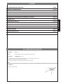
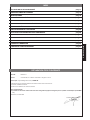
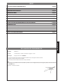
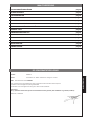
DICHIARAZIONE CE DI CONFORMITÁ
Fabbricante: GENIUS S.r.l.
Indirizzo: Via Padre Elzi, 32 - 24050 - Grassobbio- Bergamo - ITALIA
Dichiara che: L'apparecchiatura mod. SPRINT 03
• è conforme ai requisiti essenziali di sicurezza delle seguenti direttive CEE:
73/23/CEE e successiva modifica 93/68/CEE.
89/336/CEE e successiva modifica 92/31/CEE e 93/68/CEE
Nota aggiuntiva:
Questo prodotto è stato sottoposto a test in una configurazione tipica omogenea (tutti prodotti di costruzione GENIUS S.r.l.)
Grassobbio, 01 Marzo 2004
L’Amministratore Delegato
D. Gianantoni
INDICE
DICHIARAZIONE CE DI CONFORMITÁ pag.1
CARATTERISTICHE GENERALI pag.2
CARATTERISTICHE TECNICHE pag.2
PREDISPOSIZIONI pag.2
COLLEGAMENTI E FUNZIONAMENTO pag.3
LEDS DI CONTROLLO pag.4
INSERIMENTO SCHEDA RICEVITORE PER TELECOMANDO pag.4
REGOLAZIONE DEI PARAMETRI DI FUNZIONAMENTO pag.4
FUNZIONAMENTO DEL DISPLAY pag.4
PROGRAMMAZIONE pag.5
FUNZIONAMENTO DELLA FRIZIONE ELETTRONICA pag.6
SCHEMA DI COLLEGAMENTO pag.6
FUSIBILI DI PROTEZIONE pag.6
LOGICHE DI FUNZIONAMENTO pag.7

ITALIANO
2
APPARECCHIATURA ELETTRONICA PER CANCELLI SCORREVOLI 24 Vdc CON ENCODER E
FINECORSA
1. CARATTERISTICHE GENERALI
Questa centrale di comando per cancelli scorrevoli 24 Vdc con encoder offre delle elevate prestazioni ed un ampio numero di
regolazioni, con rallentamenti in apertura e chiusura, controllo motore e possibilità di gestire i finecorsa di apertura e chiusura.
Un sofisticato controllo elettronico monitorizza costantemente il circuito di potenza ed interviene bloccando la centrale in caso di
anomalie che possano pregiudicare il funzionamento della frizione elettronica.
I settaggi dei parametri e della logica di funzionamento vengono visualizzati su un comodo display che, durante il funzionamento
normale visualizza lo stato del cancello.
I motoriduttori con centrale a bordo (versioni C) richiedono l’utilizzo di un contenitore da esterno per l’alloggiamento delle n°2
batterie tampone (opzionali)
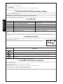
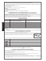
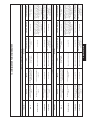
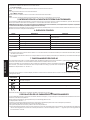
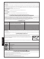
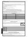
2. CARATTERISTICHE TECNICHE
Attenzione: In funzione della tensione di rete si possono avere valori d’uscita diversi sulla tensione 24V~. Prima di procedere alla
messa in servizio occorre sempre verificare la tensione d’uscita del trasformatore. Questa non deve essere superiore a 26V~ sia
per l’alimentazione a 230V~ che 115V~. La tensione deve essere misurata a vuoto, ovvero con il trasformatore alimentato e
scollegato dalla scheda.
3. PREDISPOSIZIONI
Attenzione: E’ importante per la sicurezza delle persone seguire attentamente tutte le avvertenze e le istruzioni riportate nel
presente libretto. Una errata installazione o un errato uso del prodotto può essere causa di gravi danni alle persone.
Verificare che a monte dell’impianto vi sia un adeguato interruttore differenziale, come prescritto dalle normative vigenti, e preve-
dere sulle linea di alimentazione un magnetotermico con interruzione onnipolare.
Per la messa in opera del cavi elettrici utilizzare adeguati tubi rigidi e/o flessibili. Separare sempre i cavi di collegamento degli
accessori a bassa tensione da quelli di alimentazione a 115/230 V~.
Nella versione con centrale montata sul motoriduttore, alcuni collegamenti e montaggi descritti in
queste istruzioni (motore, trasformatore, encoder, ect....) sono già precablati in fabbrica.
Nella versione con centrale nel contenitore per esterno a tenuta stagna, la lunghezza massima dei
cavi di alimentazione tra centrale e motore/encoder non deve essere superiore ai 3 m., utilizzando
cavi 2x2.5mm² per il motore e 3x0.5mm² per l’encoder ed i finecorsa (opzionali).
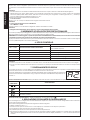
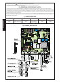
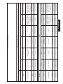
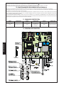
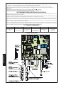
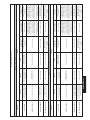
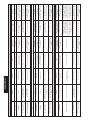
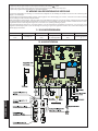
Per il fissaggio dei vari componenti nel contenitore stagno procedere come segue, con riferimento
alla fig. 1:
1) Fissare il supporto per il trasformatore toroidale nella posizione A con n°3 viti Ø4.2x13 autofilettanti
(fornite), ponendo i distanziali tra supporto e guide del contenitore stagno.
Nota bene: il supporto è dimensionato per alloggiare un trasformatore con caratteristiche e
dimensioni specificate nella tabella del paragrafo 2.
2) Fissare il trasformatore al supporto con le n°2 fascette (fornite).
3) Se è previsto l’utilizzo delle batterie tampone, fissare il relativo supporto nella posizione B con n°4
viti Ø3.5x9.5 autofilettanti (fornite) nei fori di incrocio delle guide del contenitore stagno.
erotamrofsartledenoizatnemilaidenoisneT .zH05-)%01-6+(~V032
elartnecalledenoizatnemilaidenoisneT .zH05-)
%01-6+(~V22
atibrossaaznetoP W3
erotom.xamociraC W07
irossecca.xamociraC Am005cdV42
etnaiggepmal.xamociraC .x
amW51cdV42
etneibmaarutarepmeT C°05+C°02-
enoizetorpidilibisuF 3
otnemanoiznufidehcigoL
/acitamotuaimeS/oss
apossaPacitamotuA/acitamotuA
elainimodnoC/ossaP-ossaPacitamotuaimeS
arusuihc/arutrepaidopmeT enoizammarg
orpidesafniotnemidnerppaotuanI
asuapidopmeT enoizammargorpidesafniotnemidnerppaotuanI
atnipsidazroF yalps
idetimartilibalogerillevilorttauQ
itnematnellaR otnemiderppaotuaniarusuihcearutrepanI
areittesromniisser
gnI
arutrepA/redocnE/eirettabenoizatnemilA/~V22enoizatnemilA
/potS/arusuihc-arutrepaezzeruciS/elanodeparutrepA/elatot
arusuihc-arutrepaasroceniF
oidarreperottennoC snip5odiparerottennoC
areittesromnieticsU
etn
aiggepmaL/cdV42erotoM/cdV42irosseccaenoizatnemilA
cdV42
adehcsinoisnemiD .mm541x721
~V032eladioroterotamr
ofsartehcitsirettaraC .mm04x501Ø.snemid/AV08/~V22.ces-~V032.mirp
ilanoizpoeirettabehcitsirettaraC .mm801
x07x09.snemid/hA4-V21
onretsereperotinetnocehcitsirettaraC 55PI-.mm521x522x503
Fig. 1

ITALIANO
3
Nota bene: il supporto è dimensionato per alloggiare n°2 batterie (non fornite) con caratteristiche e dimensioni specificate nella
tabella del paragrafo 2.
4) Posizionare le batterie sul supporto.
5) Fissare la centrale nella posizione C con n°4 viti Ø4.2x13 autofilettanti (fornite), ponendo i distanziali tra scheda e guide del
contenitore stagno.
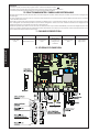
4. COLLEGAMENTI E FUNZIONAMENTO
4.1. MORSETTIERA M1
4.1.1 Open A
Morsetti “OPEN A - COM 2”. Contatto normalmente aperto. Collegare a questi morsetti un qualsiasi dispositivo (pulsante, selettore
a chiave, etc...) che comanda un’apertura totale del cancello. Il funzionamento di questo contatto è definito dal parametro D.
Nota Bene:
•Un impulso di OPEN A, apertura totale, ha sempre la precedenza su OPEN B, apertura parziale.
•Per installare più datori d’impulso collegare i contatti in parallelo.
4.1.2 Open B
Morsetti “OPEN B - COM 2”. Contatto normalmente aperto. Collegare a questi morsetti un qualsiasi dispositivo (pulsante, selettore
a chiave, etc...) che deve comandare un’apertura parziale dell’anta. L’apertura parziale non è regolabile ed è pari al 30% dell’aper-
tura totale memorizzata.
Nota Bene:
• Un impulso di OPEN A, apertura totale, ha sempre la precedenza su OPEN B, apertura parziale.
• Per installare più datori d’impulso collegare i contatti in parallelo.
4.1.3 Comando di STOP
Morsetti “STOP - COM 2”. Contatto normalmente chiuso. Collegare a questi morsetti un qualsiasi dispositivo di sicurezza (pulsante,
selettore a chiave, etc...) che deve arrestare il moto del cancello. Lo stato di questo ingresso è segnalato dal led DL2 “STOP”.
Nota Bene:
• Se non vengono collegati dispositivi di STOP ponticellare l’ingresso.
• Per installare più dispositivi di STOP collegare i contatti normalmente chiusi in serie.
4.1.4 Sicurezze in chiusura
Morsetti “FSW CL - COM 2”. Contatto normalmente chiuso. Collegare a questi morsetti un qualsiasi dispositivo di sicurezza (fotocel-
lule, costa di sicurezza, etc...) che deve intervenire sul moto di chiusura del cancello invertendo il moto del cancello sino alla massima
apertura memorizzata. Lo stato di questo ingresso è segnalato dal led DL3 “FSW-CL”.
Nota Bene:
•Se non vengono collegati dispositivi di sicurezza sul moto di chiusura ponticellare l’ingresso.
•Per installare più dispositivi di sicurezza sul moto di chiusura collegare i contatti normalmente chiusi in serie.
4.1.5 Sicurezze in apertura
Morsetti “FSW OP - COM 2”. Contatto normalmente chiuso. Collegare a questi morsetti un qualsiasi dispositivo di sicurezza (foto-
cellule, costa di sicurezza, etc...) che deve intervenire sul moto di apertura del cancello bloccandone il movimento. Al disimpegno
della sicurezza il moto riprenderà normalmente eseguendo il ciclo memorizzato. Lo stato di questo ingresso è segnalato dal led DL4
“FSW-OP”.
Nota Bene:
•Se non vengono collegati dispositivi di sicurezza sul moto di apertura ponticellare l’ingresso.
•Per installare più dispositivi di sicurezza sul moto di apertura collegare i contatti normalmente chiusi in serie.
4.2 MORSETTIERA M2
4.2.1 Encoder
Morsetti “SIG. - -ENC - +ENC”. Utilizzare l’encoder fornito con la centrale. Al morsetto “SIG:” collegare il segnale di ritorno dal morsetto
“S11” dell’encoder, al morsetto “-ENC” collegare il morsetto “-12” dell’encoder ed al morsetto “+ENC” collegare il morsetto “+13”
dell’encoder.
Nota Bene:
• Per il funzionamento della centrale è obbligatorio l’utilizzo dell’encoder
• Per il funzionamento dell’encoder rispettare il collegamento tra i morsetti sopradescritto.
4.2.2 Finecorsa in chiusura (opzionale)
Morsetti “COMF - FCC ”. Contatto normalmente chiuso. Collegare a questi morsetti l’eventuale finecorsa in chiusura. Questo
interviene arrestando il moto di chiusura del cancello. Lo stato di questo ingresso è segnalato dal led DL5 “FCC”.
Nota Bene:
•Se non viene utilizzato nessun finecorsa in chiusura è necessario ponticellare l’ingresso.
4.2.3 Finecorsa in apertura (opzionale)
Morsetti “COMF - FCA ”. Contatto normalmente chiuso. Collegare a questi morsetti l’eventuale finecorsa in apertura. Questo
interviene arrestando il moto di apertura del cancello. Lo stato di questo ingresso è segnalato dal led DL6 “FCA”.
Nota Bene:
• Se non viene utilizzato nessun finecorsa in apertura è necessario ponticellare l’ingresso.
4.3 MORSETTIERA M3
4.3.1 Lampeggiante
Morsetti “LAMP - LAMP”. Utilizzare un lampeggiante a luce fissa (il lampeggio è determinato dalla centrale) con tensione di funzio-
namento 24Vdc 15W max. E’ consigliabile collegare il lampeggiante prima della fase di programmazione della centrale in quanto
ne visualizza le fasi. Sia in apertura che in chiusura esegue un prelampeggio fisso di 1.5sec. Con il cancello aperto il lampeggiante
è spento, lampeggia solo se vengono impegnate le sicurezze in chiusura per un tempo massimo di 10 sec., segnalando che si sta
operando nell’area di movimentazione del cancello, dopodichè si spegne anche con le sicurezze in chiusura ancora impegnate.
4.3.2 Motore
Morsetti “CHM1 - APM1”. Collegare a questi morsetti il motore con alimentazione 24Vdc 70W max.
4.4 MORSETTIERA M4
4.4.1 Alimentazione
Morsetti “VAC - VAC”. Collegare a questi morsetti i fili dell’avvolgimento secondario provenienti dal trasformatore toroidale con
tensione 22V~ 50 Hz. La presenza di alimentazione è segnalata dall’accensione del Led DL1 “POWER”.

ITALIANO
4
4.4.2 Batterie (opzionali)
Morsetti “+BAT - -BAT”. Collegare a questi morsetti le n°2 batterie tampone (opzionali). Quando la centrale è alimentata, provvede
a mantenere in carica le batterie. Queste entrano in funzione nel momento in qui viene a mancare l’alimentazione del trasforma-
tore.
Nota Bene:
• Per le dimensioni e le caratteristiche delle batterie fare riferimento a quanto descritto nella tabella del paragrafo 2.
• L’alimentazione per mezzo delle batterie è da considerarsi una situazione di emergenza. Il numero di manovre eseguibili è
influenzato dalla qualità delle batterie, dalla struttura del cancello (peso, lunghezza, condizioni generali, etc...), dal tempo
trascorso dalla sospensione dell’alimentazione etc. etc..
• Rispettare la polarità di alimentazione delle batterie.
4.4.3 Accessori
Morsetti “+24 - -24”. Uscita per l’alimentazione degli accessori esterni 24Vdc.
Nota Bene:
• Il carico massimo degli accessori è di 500 mA.
4.4.4 Massa a terra
Apposito morsetto o cavo di massa. Collegare la massa a terra della rete a 230V~.
Nota Bene:
• Collegamento assolutamente necessario per il corretto funzionamento della centrale..
5. INSERIMENTO SCHEDA RICEVITORE PER TELECOMANDO
La centrale è predisposta per alloggiare un modulo radioricevitore a 5 pin. Per procedere all’installazione togliere l’alimentazione
elettrica e inserire il modulo nell’apposito connettore M5 all’interno della centrale.
ATTENZIONE: Per non danneggiare, e quindi comprometterne irrimediabilmente il funzionamento, la ricevente deve essere innestata
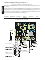
rispettando l’orientamento specificato nel paragrafo 12 (Schema di collegamento).
Seguire poi le istruzioni del radioricevitore per la memorizzazione del telecomando. Una volta memorizzato il telecomando agisce
come un qualsiasi dispositivo di comando sullo START.
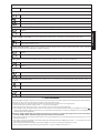
6. LEDS DI CONTROLLO
Nota Bene:
• In neretto è riportato lo stato dei leds con cancello chiuso, centrale alimentata tramihte trasformatore e finecorsa collegati.
• Nel caso non siano utilizzati i finecorsa i rispettivi contatti devono essere ponticellati ed i leds DL5 e DL6 devono sempre essere
accesi.
7. FUNZIONAMENTO DEL DISPLAY
La centrale è dotata di un comodo display per la visualizzazione dei parametri di funzionamento e per la loro programmazione. Inoltre
durante il funzionamento normale visualizza costantemente lo stato del cancello.
Durante la visualizzazione e la regolazione dei parametri il display indica a sinistra il parametro selezionato
e a destra mostra il valore corrispondente. In fig. 2 è riportato l’esempio di visualizzazione del parametro “A”
al valore “2”.
Durante il funzionamento normale il display visualizza lo stato del cancello. I valori visualizzati sono riportati nella tabella seguente:
Durante la fase di programmazione il display visualizza per tutto il tempo il valore “ ”
8. REGOLAZIONE DEI PARAMETRI DI FUNZIONAMENTO
Una volta eseguiti tutti i collegamenti necessari alimentare l’impianto e verificare che tutti i led di segnalazione siano nella situa-
zione specificata nel paragrafo 6.
Per accedere alla regolazione dei parametri seguire le indicazioni seguenti:
• Il display visualizza il valore “– –”.
• Premere e tenere premuto il tasto P2 fino a che il display non visualizza il nome del primo parametro.
• Per modificare il valore del parametro premere il pulsante P1.
• Per passare al parametro successivo premere nuovamente il pulsante P2.
• Trascorsi 60 secondi senza che si tocchi nessun tasto la centrale esce dalla modalità regolazione. E’ possibile uscire manualmente
dalla modalità di regolazione facendo scorrere tutti i parametri. Quando i display visualizzano “– –” si è tornati al funzionamento
normale.
DELOSECCAOTNEPS
1LD REWOP- erotamrofsartetimartatatnemilaelartneC
atatnemilaelartnecoenoizatnemilaidaznacna
M
enopmateirettabelnoc
2LD POTS- ovittaniodnamoC otavittaodnamoC
3LD LC-WSF- arebilazzeruciS atangepmiazzeruci
S
4LD PO-WSF- arebilazzeruciS atangepmiazzeruciS
5LD CCF-orebilarusuihcniasroceniF otangepmiarusuihcniasrocen
iF
6LD ACF- orebilarutrepaniasroceniF otangepmiarutrepaniasroceniF
EROLAV
OTAZZILAUSIV
OLLECNACOTATS
osopiraollecnaC
arutrepaniollecnaC
)ovisseccusofargarapidev,atatilibaaci
tamotuaarusuihcirnocoloS(asuapniotrepaollecnaC
arusuihcniollecnaC
Fig. 2

ITALIANO
5
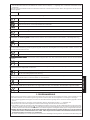
Nella tabella seguente sono riassunti i vari parametri ed i valori assegnabili.
9. PROGRAMMAZIONE
Durante la procedura di programmazione la centrale memorizza le battute meccaniche in apertura, in chiusura e l’eventuale tempo
di pausa. Per eseguire la procedura di programmazione seguire le seguenti istruzioni:
• Sbloccare il motoriduttore, portare il cancello a metà della corsa d’apertura, ribloccare il motoriduttore.
• Alimentare la centrale e verificare che sul display venga visualizzato il valore “– –”
• Tenere premuto per circa 5 secondi il tasto P2, la centrale mostra il valore del primo parametro.
• Dare un impulso di OPEN A con un pulsante e qualsiasi altro dispositivo che comandi un’apertura totale del cancello, il display
visualizza il valore “ ” ed il cancello inizia una manovra di chiusura sino al fermo meccanico di chiusura, o al finecorsa in
chiusura se previsto ed abilitato (vedi paragrafo precedente).
Attenzione: se la prima manovra che l’operatore esegue durante la fase di programmazione è in apertura è necessario togliere
tensione ed invertire i fili collegati ai morsetti “CHM1 - APM1”. Ripetere la procedura di programmazione dal primo punto.
• Dopo una pausa di circa 2 secondi il cancello esegue un’apertura totale siano alla battuta meccanica di apertura o al relativo
finecorsa.
• Se la chiusura automatica non è abilitata la fase di programmazione è conclusa ed il display visualizza il valore “– –”, viceversa
la centrale inizia il conteggio del tempo di pausa.
• Trascorso il tempo desiderato dare nuovamente un comando di OPEN A ed il cancello inizierà la fase di chiusura.
• Una volta ultimata la fase di chiusura la programmazione è conclusa ed il dispay visualizza il valore”– –”.
YALPSID ENOIZIRCSED
.erotomledazrofalledeacinortteleenoizirfalledàtilibisnesalledenoizalogeR
olocatso'll
aelibisnesùip,aminimerotomazroF
olocatso'llaàtilibisnesassab,assab-oidemerotomazroF
olocatso'llaàtilibi
snesatla,atla-oidemerotomaroF
olocatso'llaàtilibisnesatla,atlaerotomazroF
:acitamotuAarusuihciR ollecnac
ledacitamotuaarusuihciralatilibasidoatilibaisenoiznufatseuqnoc
atavittasiD
atavittA
:ANEPOodnamocledotne
manoiznuF .)elatotarutrepa(ANEPOidetnaslupledotnematropmoclianimretedenoiznufatseuq
erpA/eduihC/erpA
pot
S/eduihC/potS/erpA
:atamitluarusuihcaenoisrevni'doploC acricàripmoc,arusuihciaesafalledenimretla,ollecn
aclienoiznufatseuqatilibaises
.otnemanoizaelautneve'lenodnalovega,occolbsidovitisopsidlieraciracsidett
emrepotseuQ.arutrepaniorigozzem
atavittasiD
atavittA
:elainimodnocenoiznuF .tratsidodnamocliotibiniàrrevo
llecnacledarutrepaidesafaletnarudenoiznufatseuqodnavitta
atavittasiD
atavittA
:otnematnellaridotnupelaut
necreP eudiartodneilgecs,otatnellarottartledazzehgnulalatsopmiisortemarapotseuqnoc
itassiferpirolav
ataz
ziromemarutrepaamissamalled%02
atazziromemarutrepaamissamalled%01
:atatnellaresafaletnarudàticoleV ,atat
nellaresafaletnaruderotomledàticolevaleratsopmielibissopèortemarapotseuqnoc
irolaveudiartodneilgecs
ass
aB
atlA
.asrocenifiehcnaitazzilituonognevesolosatavittaereseevedenoiznufatseuq:asrocenifnocotnemanoiznu
F
redocnenocoloS
asroceniferedocnE

ITALIANO
6
Nota Bene:
• Durante tutta la procedura di programmazione il display visualizzerà il valore “ ”.
• Per tutto il tempo della programmazione il lampeggiante rimarrà acceso con luce fissa.
• Durante la fase di programmazione il moto del cancello sarà rallentato.
10. FUNZIONAMENTO DELLA FRIZIONE ELETTRONICA
Dispositivo importantissimo ai fini della sicurezza, la sua taratura resta costante nel tempo senza essere soggetta ad usure o cambia-
menti di taratura.
Essa è attiva sia in chiusura che in apertura, quando interviene inverte la marcia senza disabilitare la chiusura automatica nel caso
essa sia inserita.
Se interviene per 2 volte consecutive, si posiziona in STOP disabilitando qualsiasi comando automatico, questo perché intervenendo
per 2 volte significa che l’ostacolo permane e potrebbe essere pericoloso effettuare qualsiasi manovra ulteriore costringendo così
l’utente a dare un comando di apertura o chiusura.
Se interviene per più di 90 Sec. consecutivi la centrale esegue una procedura di EMERGENZA dove andrà ad effettuare obbligato-
riamente una apertura completa tutta in rallentamento sino al fermo battuta di apertura per poi richiudersi automaticamente in
modo da risincronizzarsi le battute autonomamente.
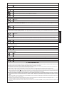
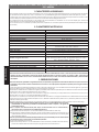
11. FUSIBILI DI PROTEZIONE
12. SCHEMA DI COLLEGAMENTO
ELIBISUFENOIZETORPELIBISUFENOIZETORPELIBISUFENOIZETORP
-V052/A01T=1F
02x5
V22enoizatnemilA
-V052/A5.0T=2F
02x5
e
noizatnemilA
eirossecca
eirettabacirac
-V052/A5.0R=3F
02x5
aticsU
etnaiggepmal

ITALIANO
7
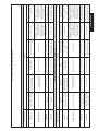
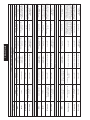
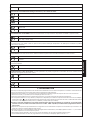
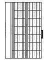
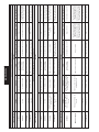
13. LOGICHE DI FUNZIONAMENTO
0=F0=d1=CacitamotuA"A"acigoL
ollecnacotatS islupmI
AnepOBnepOpotSarutrepaezzeruciSarusuihcezzeruciSHC/PAazzer
uciS
osuihC
eduihcireatna'lerpA
asuapidopmetopod
elaizraparutrepa'leugesE
opododneduihciratna'lled
asuapido
pmet
otteffenusseN
)otibiniNEPO(
NEPOididnamociecsibinIotteffenusseN
ididnamociecsibinI
NEPO
asuapniotrepA as
uapidopmetaciraciR
ollecnaclieduihciR
etnemataidemmi
otnemanoiznufliaccolBotteffenusseN
laearusuihciralacc
olB
opodeduihcirongepmisid
liosrocsartèes.ces5
,asuapidopmet
ollaeduihcirasreveciv
idopmetlederedacs
.otats
opmiasuap
laearusuihciralaccolB
opodeduihcirongepmisid
liosrocsartèes.ces5
,asuapidopmet
ollaeduihcirasrev
eciv
idopmetlederedacs
.otatsopmiasuap
arusuihcnI
ledotomlietrevnI
ollecnac
otteffenusseNotnemanoiznufliacco
lBotteffenusseNotomlietrevnI
otnemanoiznufliaccolB
etrevniongepmisidlade
arutrepanI
ledotomlietrevnI
ollecna
c
otteffenusseNotnemanoiznufliaccolB
otnemanoiznufliaccolB
ednerpirongepmisidlade
otteffenusseN
otnemanoizn
ufliaccolB
ednerpirongepmisidlade
0=F1=d1=CossaP-ossaPacitamotuA"PA"acigoL
ollecnacotatS islupmI
AnepOBnepOpotSarutrepaezzeruciSarusuihcezzeru
ciSHC/PAazzeruciS
osuihC
eduihcireatna'lerpA
asuapidopmetopod
elaizraparutrepa'leugesE
opododneduihciratna'
lled
asuapidopmet
otteffenusseN
)otibiniNEPO(
ididnamociecsibinI
NEPO
otteffenusseN
ididnamociecsibinI
NEPO
as
uapniotrepA asuapidopmetaciraciR
ollecnaclieduihciR
etnemataidemmi
otnemanoiznufliaccolBotteffenusseN
laear
usuihciralaccolB
opodeduihcirongepmisid
liosrocsartèes.ces5
,asuapidopmet
ollaeduihcirasreveciv
idopmetlederedacs
.otatsopmiasuap
laearusuihciralaccolB
opodeduihcirongepmisid
liosrocsartèes.ces5
,asuapidopmet
olla
eduihcirasreveciv
idopmetlederedacs
.otatsopmiasuap
arusuihcnI
ledotomliaccolB
ovisseccusla,ollecnac
erpaos
lupmi
otteffenusseNotnemanoiznufliaccolBotteffenusseNotomlietrevnI
otnemanoiznufliaccolB
etrevniongepmisidl
ade
arutrepanI
ledotomliaccolB
ovisseccusla,ollecnac
eduihcoslupmi
otteffenusseNotnemanoiznufliaccolB
otnema
noiznufliaccolB
ednerpirongepmisidlade
otteffenusseN
otnemanoiznufliaccolB
ednerpirongepmisidlade

ITALIANO
8
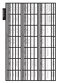
0=F0=d0=CacitamotuaimeS"E"acigoL
ollecnacotatS islupmI
AnepOBnepOpotSarutrepaezzeruciSarusuihcezzeruciSHC/PAa
zzeruciS
osuihC atna'lerpAelaizraparutrepa'leugesE
otteffenusseN
)otibiniNEPO(
ididnamociecsibinI
NEPO
otteff
enusseN
ididnamociecsibinI
NEPO
otrepA eduihCollecnaclieduihC
otteffenusseN
)otibiniNEPO(
ididnamociecsibinI
N
EPO
idodnamocecsibinI
.NEPO
idodnamocecsibinI
ongepmesidlaNEPO
.ces5opodeduihcir
arusuihcnI
ledotomlietrevnI
ollecnac
otteffenusseNotnemanoiznufliaccolBotteffenusseN
ledotomlietrevnI
ollecnac
otnemanoiznufliaccolB
etrevniongepmisidlade
arutrepanI
ledotomlietrevnI
ollecnac
otteffenusseNotnemanoiznufliaccolB
deotnemanoiznufl
iaccolB
ednerpirongepmisidla
otteffenusseN
otnemanoiznufliaccolB
ednerpirongepmisidlade
0=F1=d0=CossaP-ossaPacitamotuaimeS"PE"acigoL
ollecnacotatS islupmI
AnepOBnepOpotSarutrepaezzeruciSarusuihcez
zeruciSHC/PAazzeruciS
osuihC atna'lerpAelaizraparutrepa'leugesE
otteffenusseN
)otibiniNEPO(
ididnamociecsibi
nI
NEPO
otteffenusseN
ididnamociecsibinI
NEPO
otrepA eduihCollecnaclieduihC
otteffenusseN
)otibiniNEPO(
ididnam
ociecsibinI
NEPO
idodnamocecsibinI
.NEPO
idodnamocecsibinI
ongepmesidlaNEPO
.ces5opodeduihcir
arusuihcnI
otne
manoiznufliaccolB
ovisseccusla,ollecnacled
erpaoslupmi
otteffenusseNotnemanoiznufliaccolBotteffenusseN
ledo
tomlietrevnI
ollecnac
otnemanoiznufliaccolB
etrevniongepmisidlade
arutrepanI
ledotnemanoiznufliaccolB
oviss
eccusla,ollecnac
eduihcoslupmi
otteffenusseNotnemanoiznufliaccolB
deotnemanoiznufliaccolB
ednerpirongepmis
idla
otteffenusseN
otnemanoiznufliaccolB
ednerpirongepmisidlade
1=F0=d1=CelainimodnoC"D"acigoL
ollecnacotatS islupmI
AnepOBnepOpotSarutrepaezzeruciSarusuihcezzeruciSHC/PAazz
eruciS
osuihC
eduihcireatna'lerpA
asuapidopmetopod
elaizraparutrepa'leugesE
odneduihciratna'lled
asuapidopm
etopod
otteffenusseN
)otibiniNEPO(
ididnamociecsibinI
NEPO
otteffenusseN
ididnamociecsibinI
NEPO
asuapniotrep
A asuapidopmetaciraciR
ollecnaclieduihciR
etnemataidemmi
otnemanoiznufliaccolBotteffenusseN
laearusuihciralaccolB
5opodeduihcirongepmisid
idopmetliosrocsartèes.ces
eduihcirasreveciv,asuap
idopmetlederedacsolla
.ot
atsopmiasuap
laearusuihciralaccolB
5opodeduihcirongepmisid
idopmetliosrocsartèes.ces
eduihcirasreveciv,as
uap
idopmetlederedacsolla
otatsopmiasuap
arusuihcnI
ledotomlietrevnI
ollecnac
otteffenusseNotnemanoiznufliac
colBotteffenusseNotomlietrevnI
otnemanoiznufliaccolB
etrevniongepmisidlade
arutrepanI otteffenuffeNotteffenu
sseNotnemanoiznufliaccolB
deotnemanoiznufliaccolB
ednerpirongepmisidla
otteffenusseN
otnemanoiznufliaccolB
ednerpirongepmisidlade

ENGLISH
9
EC COMPLIANCE DECLARATION
Manufacturer: GENIUS s.r.l.
Address: Via Padre Elzi, 32 - 24050 - Grassobbio - Bergamo-ITALY
Declares that: the SPRINT 03 electronic
• complies with the essential safety requirements in the following EEC Directives:
73/23 EEC and subsequent amendment 93/68 EEC.
89/336 EEC and subsequent amendments 92/31 EEC and 93/68 EEC.
Notes:
these products have been subject to testing procedures carried out under standardised conditions (all products manufactured by
GENIUS s.r.l.)
Grassobbio, 1 March 2004
Managing Director
D. Gianantoni
CONTENTS
EC COMPLIANCE DECLARATION pag.9
GENERAL CHARACTERISTICS pag.10
PRELIMINARY SETTING-UP pag.10
TECHNICAL SPECIFICATIONS pag.10
CONNECTIONS AND OPERATION pag.11
INSTALLING A RECEIVER CARD FOR REMOTE-CONTROL pag.12
CONTROL LEDS pag.12
OPERATION OF DISPLAY pag.12
ADJUSTING THE OPERATING PARAMETERS pag.12
PROGRAMMING pag.13
OPERATION OF ELECTRONIC CLUTCH pag.14
PROTECTION FUSES pag.14
CONNECTION LAY-OUT pag.14
FUNCTION LOGICS pag.15

ENGLISH
10
remrofsnartfoegatlovylppuS .zH05-)%01-6+(~V032
tinulortnocfoegatlovylppuS .zH05-)%01-6+(~V22
rewopdebrosb
A W3
daolxamrotoM W07
daolxamseirosseccA Am005cdV42
daol.xampmalgnihsalF .xamW51cdV42
erutarepmettneibmagnita
repO C°05+C°02-
sesufnoitcetorP 3
scigolnoitcnuF
deppetS/citamotuaimeS/citamotuAdeppetS/citamotuA
/citamotu
aimeS
epytodnoC
emitgnisolc/gninepO gnimmargorpgnirudgninrael-fleshguorhT
emitesuaP gnimmargorpgnirudgninr
ael-fleshguorhT
ecroftsurhT yalpsidnoelbatsujdaslevelruoF
snoitareleceD gnisolcdnagninepognirudgninrael-f
leshguorhT
stupnidraoblanimreT
/gninepolatoT/redocnE/ylppusyrettaB/~V22ylppusrewoP
/potS/secivedytefasgn
isolc-gninepO/gnineponairtsedeP
hctiws-timilgnisolc-gninepO
rotcennocoidaR rotcennocnip-5dipaR
stuptuodra
oblanimreT
pmalgnihsalF/rotoMcdV42/seirosseccaotylppusrewopcdV42
cdV42
snoisnemiddraoB .mm541x721
remrofsn
artladiorot~V032foscitsiretcarahC .mm04x501Ø.snemid/AV08/~V22.ces-~V032.mirp
seirettablanoitpofoscitsir
etcarahC .mm801x07x09.snemid/hA4-V21
erusolcneroodtuofoscitsiretcarahC 55PI-.mm521x522x503
ELECTRONIC CONTROL UNIT FOR 24 Vdc SLIDING GATES WITH ENCODER AND LIMIT-
SWITCH
1. GENERAL CHARACTERISTICS
This control unit for 24 Vdc sliding gates with encoder offers high performance and a wide range of adjustments: opening and closing
decelerations, motor control and a facility for managing the opening and closing limit-switches.
A sophisticated electronic control constantly monitors the power circuit and disables the control unit in the event of malfunctions
that could impair efficiency of the electronic clutch.
The parameter settings and the operating logic are shown on a handy display, which, indicates gate status during normal operation.
The gearmotors with on-board control unit (C versions) require an outdoor enclosure to house the 2 buffer batteries (optional).
2. TECHNICAL SPECIFICATIONS
Attention: different output values on voltage 24V~ are possible according to the mains voltage. Before starting, always check the
transformer output voltage. It shall not exceed 26V~ both for the 230V~ power supply and 115V~ power supply. Voltage is to be
measured loadless, i.e. when the transformer is supplied with power but disconnected from the board.
3. PRELIMINARY SETTING-UP
Attention: To ensure people's safety, all warnings and instructions in this booklet must be carefully observed. Incorrect installation or
incorrect use of the product could cause serious harm to people.
Make sure there is an adequate differential switch upstream of the system as specified by current laws, and install a thermal breaker
with all-pole switching on the electrical supply line.
To lay electric cables, use adequate rigid and/or flexible pipes. Always separate the connection cables of low voltage accessories
from the 115/230 V~ power cables.
In the version with control unit installed on the gearmotor, some connections and installations described in these instructions (motor,
transformer, encoder, etc) are factory wired.
In the version with control unit in the watertight outdoor enclosure, maximum length of connection cables between control unit
and motor/encoder must not exceed 3 m., using 2x2.5mm² cables for the motor and 3x0.5mm² cables for the encoder and for the
limit-switches (optional).
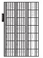
Procedure for securing components in the waterproof enclosure, referring to fig. 1:
1) Secure the support for the toroidal transformer in position A, using 3 Ø4.2x13 self-tapping screws
(supplied), placing the spacers between the support and the guides of the watertight enclosure.
NB.: the support is sized to house a transformer with the characteristics and dimensions specified
on the table in paragraph 2.
2) Secure the transformer to the support with 2 clamps (supplied).
3) If using buffer batteries, secure the relevant support in position B with 4 Ø3.5x9.5 self-tapping
screws (supplied) in the crossover holes of the guides of the watertight enclosure.
NB.: the support is sized to house 2 batteries (not supplied) with the characteristics and dimensions
specified on the table in paragraph 2.
4) Position the batteries on the support.
5) Secure the control unit in position C with 4 Ø4.2x13 self-tapping screws (supplied), placing the
spacers between the board and the guides of the watertight enclosure.
Fig. 1

ENGLISH
11
4. CONNECTIONS AND OPERATION
4.1. TERMINAL BOARD M1
4.1.1 Open A
Terminals “OPEN A - COM 2”. Normally open contact. Connect, to these terminals, any device (push-button, key selector, etc.) that
commands total opening of the gate. The operation of this contact is defined by parameter D.
NB.:
•An OPEN A pulse, total opening, always has priority on OPEN B, partial opening.
•To install several pulse generators, connect the contacts in parallel.
4.1.2 Open B
Terminals “OPEN B - COM 2”. Normally open contact. Connect, to these terminals, any device (push-button, key selector, etc.) that
must command partial opening of the leaf. Partial opening is non-adjustable and equals 30% of the memory-stored total opening.
NB.:
• An OPEN A pulse, total opening, always has priority on OPEN B, partial opening.
• To install several pulse generators, connect the contacts in parallel.
4.1.3 STOP command
Terminals “STOP - COM 2”. Normally closed contact. Connect, to these terminals, any safety device (push-button, key selector, etc.)
that must stop gate movement. The status of this input is signalled by LED DL2 “STOP”.
NB.:
• If no STOP devices are connected, jumper connect the input.
• To install several STOP devices, connect the normally closed contacts in series.
4.1.4 Closing safety devices
Terminals “FSW CL - COM 2”. Normally closed contact. Connect, to these terminals, any safety device (photocells, safety edge, etc.)
that must control gate closing motion by reversing gate movement up to the maximum memory-stored opening. The status of this
input is signalled by LED DL3 “FSW-CL”.
NB.:
• If no closing safety devices are connected to the closing motion, jumper connect the input.
• To install several safety devices on the closing motion, connect the normally closed contacts in series.
4.1.5 Opening safety devices
Terminals “FSW OP - COM 2”. Normally closed contact. Connect, to these terminals, any safety device (photocells, safety edge, etc.)
that must control gate opening motion by stopping its movement. When the safety device is released, motion will resume normally,
executing the memory-stored cycle. The status of this input is signalled by LED DL4 “FSW-OP”.
NB.:
• If no safety devices are connected to the opening motion, jumper connect the input:
• To install several safety devices on the opening motion, connect the normally closed contacts in series.
4.2 M2 TERMINAL BOARD
4.2.1 Encoder
Terminals “SIG. - -ENC - +ENC”. Use the encoder supplied with the control unit. On the “SIG” terminal: connect the return signal from
encoder terminal “S11”; connect encoder terminal “-12” to the “-ENC” terminal; connect encoder terminal “+13” to terminal
“+ENC”.
NB.:
• The encoder must be used for operation of the control unit
• For encoder operation, observe the connection between terminals as described above.
4.2.2 Closing limit switch (optional)
Terminals “COMF - FCC”. Normally closed contact. Connect the closing limit-switch, if any, to these terminals. The switch operates
by stopping the gate closing motion. The status of this input is signalled by LED DL5 “FCC”.
NB.:
•If no closing limit-switch is used, the input must be jumper connected.
4.2.3 Opening limit switch (optional)
Terminals “COMF - FCA”. Normally closed contact. Connect the opening limit-switch, if any, to these terminals. The switch operates
by stopping the gate opening motion. The status of this input is signalled by LED DL6 “FCA”.
NB.:
• If no opening limit-switch is used, the input must be jumper connected.
4.3 M3 TERMINAL BOARD
4.3.1 Flashing Lamp
Terminals “LAMP - LAMP”. Use a flashing-lamp with steady light (flashing is produced by the control unit) on operating voltage of 24
Vdc 15W max. It is recommended to connect the flashing lamp before programming the control unit, because its phases are
displayed. A 1.5 sec. pre-flashing steady light goes on during both opening and closing. When the gate is open, the flashing-lamp
is OFF, and only flashes when the closing safety devices are engaged for a maximum time of 10 sec, signalling that one is operating
in the gate movement area, after which the flashing-lamp goes OFF even with the closing safety devices still engaged.
4.3.2 Motor
Terminals “CHM1 - APM1”. Connect, to these terminals, the motor with a power supply of 24Vdc 70W max.
4.4 TERMINAL BOARD M4
4.4.1 Power supply
Terminals “VAC - VAC”. Connect, to these terminals, the secondary winding wires arriving from the toroidal transformer with voltage
of 22V~ 50 Hz. Power ON is indicated by the lighting up of LED DL1 “POWER”.
4.4.2 Batteries (optional)
Terminals “+BAT - - BAT”. Connect the 2 buffer batteries (optional) to these terminals. When the control unit is powered, it will keep
the batteries charged. The batteries come into operation when the transformer does not supply power.
NB.:
• For battery dimensions and characteristics, refer to the descriptions on the table in paragraph 2.
• Power supply provided by the batteries should be considered an emergency situation. The number of possible manoeuvres
depends on the quality of the batteries, the gate's structure (weight, length, general conditions, etc.), and on the time since
power was cut, etc, etc.
• Observe the battery supply polarity.

ENGLISH
12
DELNOFFO
1LD REWOP- remrofsnartybdeilppustinulortnoC
ehtybdeilppustinulortnocro,deilppusrewopoN
seirettabref
fub
2LD POTS- evitcanidnammoC delbanednammoC
3LD LC-WSF- eerfecivedytefaS degagnesecivedytefaS
4LD PO-WSF- eerfe
civedytefaS degagnesecivedytefaS
5LD CCF-eerfhctiwstimilgnisolC degagnehctiwstimilgnisolC
6LD ACF- eerfhctiws
timilgninepO degagnehctiwstimilgninepO
EULAVYALPSID SUTATSETAG
tsertaetaG
gninepoetaG
.)hpargaraptxenees-delbaneerusolc-ercitamotuahtiwylnO(suta
tsesuapninepoetaG
gnisolcetaG
4.4.3 Accessories
Terminals “+24 - -24”. Output for power supply to 24Vdc outside accessories.
NB.:
• Maximum load of accessories is 500 mA.
4.4.4 Earthing
An appropriate earthing terminal or cable. Earth connect the mains supplying 230V~.
NB.:
• The connection is essential for correct operation of the control unit.
5. INSTALLING A RECEIVER CARD FOR REMOTE-CONTROL
The control unit is designed to house a 5-pin radio-receiver module. To install, cut out power and fit the module in the appropriate
M5 connector inside the control unit.
ATTENTION: To avoid damaging the receiver and thus irreparably impairing its operation, the receiver must be installed while
observing the fitting direction specified in paragraph 12 (Connection lay-out).
This done, observe the radio-receiver instructions for memory-storing the remote control. When the remote control has been stored,
it controls START just like any command device.
6. CONTROL LEDS
NB.:
• Indicated in bold: status of LEDs with the gate closed, control unit supplied by transformer, and limit-switches connected.
• If the limit-switches are not used, the relevant contacts must be jumper connected and the DL5 and DL6 LEDs must always be
ON.
7. OPERATION OF DISPLAY
The control unit has a handy display for viewing and programming the operating parameters. Furthermore, it constantly shows gate
status during normal operation.
When parameters are being displayed and adjusted, the display shows the selected parameter on the left,
and the relevant value on the right. Fig. 2 shows a display example of parameter “A” at value “2”.
During normal operation, the display shows gate status. The displayed values are indicated on the following table:
During programming, the display shows value “ ” for the whole time.
8. ADJUSTING THE OPERATING PARAMETERS
When you have made all the necessary connections, power up the system and check if all the signalling LEDs are in the condition
specified in paragraph 6.
To access parameter adjustment, follow the instructions below:
• Display shows value “– –”.
• Press and hold down key P2 until the display shows the name of the first parameter.
• Press push-button P1 to change the value of the parameter.
• To move on to the next parameter, press push-button P2 again..
• When 60 seconds have elapsed without any key being touched, the control unit exits the adjustment mode. You can manually
exit the adjustment mode by scrolling all the parameters. When the displays show “– –” , you have returned to normal operation.
Fig. 2

ENGLISH
13
YALPSID NOITPIRCSED
.ecrofrotomdnahctulccinortcelefotnemtsujdaytivitisneS
.elcatsbootevitisneserom,ecrof
rotommuminiM
.elcatsbootytivitisneswol,ecrofrotomwol-muideM
.elcatsbootytivitisneshgih,ecrofrotomhgih-m
uideM
.elcatsbootytivitisneshgih,ecrofrotomhgiH
:erusolc-ercitamotuA .gnisolcetagcitamotuaselbasidroselb
anenoitcnufsiht
delbasiD
delbanE
:dnammocANEPOfonoitarepO .nottub-hsup)gninepolatot(ANEPOehtforuoivahebeh
tsenimretednoitcnufsiht
snepO/sesolC/snepO
spotS/sesolC/spotS/snepO
:gnisolcretfaekortsgnisreveR swollasi
hT.gnisolcretfa,ekortsgninepostiflahtuobatceffelliwetageht,delbanesinoitcnufsihtfi
.noitarepoelbissops
tignitatilicaf,ecivedesaelerehteveilerot
delbasiD
delbanE
:noitcnufodnoC .detibihnisidnammoctratseht,dene
pogniebsietagehtelihwdelbanesinoitcnufsihtfi
delbasiD
delbanE
:egatnecreptniopnoitareleceD tesowtehtmorft
ignitceles,noitcesdetarelecedehtfohtgnelehttesotdesusiretemarapsiht
.seulav
gninepoderots-yromemmumixam
fo%02
gninepoderots-yromemmumixamfo%01
:esahpdetarelecedgniruddeepS ehtmorftignitceles,esahpdetarelecede
htgniruddeepsrotomtesotdesusiretemarapsiht
.seulavowt
woL
hgiH
.desugnieboslaerasehctiws-timilehtfiylnode
lbaneebtsumnoitcnufsiht:sehctiwstimilhtiwnoitarepO
ylnoredocnehtiW
hctiws-timildnaredocnE
The following table summarises the different parameters and the assignable values.
9. PROGRAMMING
During the programming procedure, the control unit memory-stores the mechanical stop points during opening, closing, and any
pause time. To carry out the programming procedure, follow these instructions:
• Release the gearmotor, take the gate to halfway its opening stroke, and them re-lock the gearmotor.
• Power up the control unit and check if value “– –” is shown on the display.
• Hold down key P2 for about 5 seconds - the control unit shows the value of the first parameter.
• Give an OPEN A pulse, using a push-button and any other device commanding total gate opening, the display shows value “ ”
, and the gate begins a closing manoeuvre up to the mechanical closing stop, or up to the closing limit-switch, if supplied and
enabled (see previous paragraph).
Attention: if, during programming, the operator's first manoeuvre is opening, cut power and change over the wires connected to
terminals “CHM1 - APM1”. Repeat the programming procedure from the first point.
• After a pause of about 2 seconds, the gate carries out a total opening either up to the opening mechanical stop point or to the
relevant limit-switch.
• If automatic closing is not enabled, this means programming has finished and the display shows value “– –”. Vice versa, the control
unit begins counting pause time.
• When the required time has elapsed, give another OPEN A command, and the gate will begin to close.
• When closing has finished, programming has terminated too, and the display shows value “– –”.

ENGLISH
14
ESUFNOITCETORPESUFNOITCETORPESUFNOITCETORP
-V052/A01T=1F
02x5
V22ylppusrewoP
-V052/A5.0T=2F
02x5
otylppuS
dnaseir
ossecca
regrahc-yrettab
-V052/A5.0R=3F
02x5
pmalgnihsalF
tuptuo
N.B.:
• The display shows value “ ” during the entire programming procedure.
• The flashing lamp stays lighted on a steady light during the entire programming time.
• Gate motion is decelerated during programming.
10. OPERATION OF ELECTRONIC CLUTCH
A very important device for reasons of safety. Its setting stays unchanged long-term, without wear or any setting changes.
It is active during both closing and opening. When it operates, it reverses movement without disabling automatic closing if enabled.
If it operates twice consecutively, it goes into STOP status, disabling any automatic command. This is because, as the clutch operates
twice, it means that the obstacle remains and it could be dangerous to perform any further manoeuvre, therefore forcing the user
to give an opening or closing command.
If the clutch operates for more than 90 consecutive seconds, the control unit performs an EMERGENCY procedure and will carry out
a complete opening in decelerated mode up to the opening stop-point, and then will close automatically so that stop-points are
independently re-synchronised.
11. PROTECTION FUSES
12. CONNECTION LAY-OUT

ENGLISH
15
0=F0=d1=Ccigol"A"citamotuA
sutatsetaG sesluP
AnepOBnepOpotSsecivedytefasgninepOsecivedytefasgnisolCecivedytef
asLC/PO
desolC
sesolc-erdnafaelehtsnepO
emitesuapretfa
gninepolaitrapfaelsetucexE
esuapretfasesolc-erdna
em
it
tceffeoN
)delbasidNEPO(
sdnammocNEPOselbasiDtceffeoNsdnammocNEPOselbasiD
esuapnonepO emitesuapsdaoleR
etag
ehtsesolc-eR
yletaidemmi
noitarepospotStceffeoN
no,dnagnisolc-erselbasiD
5retfasesolc-er,esaeler
sahemitesuapfisdnoces
-erti,asrev-eciV.despale
emitesuaptesnehwsesolc
despalesah
no,dnagnisolc-erselbasiD
5retfaseso
lc-er,esaeler
sahemitesuapfisdnoces
-erti,asrev-eciV.despale
emitesuaptesnehwsesolc
despalesah
gnisolC noit
ometagsesreveRtceffeoNnoitarepospotStceffeoNnoitomsesreveR
dnanoitarepospotS
esaelernosesrever
gninepO noitom
etagsesreveRtceffeoNnoitarepospotS
dnanoitarepospotS
esaelernosemuser
tceffeoN
dnanoitarepospotS
esaelernose
muser
0=F1=d1=Ccigol"PA"citamotuAdeppetS
sutatsetaG sesluP
AnepOBnepOpotSsecivedytefasgninepOsecivedytefasgnisolCec
ivedytefasLC/PO
desolC
sesolc-erdnafaelehtsnepO
emitesuapretfa
gninepolaitrapfaelsetucexE
esuapretfasesolc
-erdna
emit
tceffeoN
)delbasidNEPO(
sdnammocNEPOselbasiDtceffeoNsdnammocNEPOselbasiD
esuapnonepO emitesuapsda
oleR
etagehtsesolc-eR
yletaidemmi
noitarepospotStceffeoN
no,dnagnisolc-erselbasiD
5retfasesolc-er,esaeler
sa
hemitesuapfisdnoces
-erti,asrev-eciV.despale
emitesuaptesnehwsesolc
despalesah
no,dnagnisolc-erselbasiD
5r
etfasesolc-er,esaeler
sahemitesuapfisdnoces
-erti,asrev-eciV.despale
emitesuaptesnehwsesolc
despalesah
gni
solC
dnanoitometagspotS
esluptxennosnepo
tceffeoNnoitarepospotStceffeoNnoitomsesreveR
dnanoitarepospotS
esael
ernosesrever
gninepO
dnanoitometagspotS
esluptxennosesolc
tceffeoNnoitarepospotS
dnanoitarepospotS
esaelerno
semuser
tceffeoN
dnanoitarepospotS
esaelernosemuser
13. FUNCTION LOGICS

ENGLISH
16
0=F0=d0=Ccigol"E"citamotua-imeS
sutatsetaG sesluP
AnepOBnepOpotSsecivedytefasgninepOsecivedytefasgnisolCecive
dytefasLC/PO
desolC faelehtsnepOgninepolaitrapsetucexE
tceffeoN
)delbasidNEPO(
sdnammocNEPOselbasiDtceffeoNsd
nammocNEPOselbasiD
nepO sesolCetagehtsesolC
tceffeoN
)delbasidNEPO(
sdnammocNEPOselbasiDdnammocNEPOselbasiD
d
nammocNEPOselbasiD
sesolc-er,esaelerno,dna
..ces5retfa
gnisolC noitometagsesreveRtceffeoNnoitarepospotStceff
eoNnoitometagsesreveR
dnanoitarepospotS
esaelernosesrever
gninepO noitometagsesreveRtceffeoNnoitarepospotS
dn
anoitarepospotS
esaelernosemuser
tceffeoN
dnanoitarepospotS
esaelernosemuser
0=F1=d0=Ccigol"PE"citamotua-imeSdeppetS
sutatsetaG sesluP
AnepOBnepOpotSsecivedytefasgninepOsecivedytefasgni
solCecivedytefasLC/PO
desolC faelehtsnepOgninepolaitrapsetucexE
tceffeoN
)delbasidNEPO(
sdnammocNEPOselbasiDt
ceffeoNsdnammocNEPOselbasiD
nepO sesolCetagehtsesolC
tceffeoN
)delbasidNEPO(
sdnammocNEPOselbasiDdnammocNEPOs
elbasiD
dnammocNEPOselbasiD
sesolc-er,esaelerno,dna
..ces5retfa
gnisolC
dnanoitarepoetagspotS
esluptxennosn
epo
tceffeoNnoitarepospotStceffeoNnoitometagsesreveR
dnanoitarepospotS
esaelernosesrever
gninepO
dnanoitometa
gspotS
esluptxennosesolc
tceffeoNnoitarepospotS
dnanoitarepospotS
esaelernosemuser
tceffeoN
dnanoitarepospotS
esaelernosemuser
1=F0=d1=Ccigol"D"odnoC
sutatsetaG sesluP
AnepOBnepOpotSsecivedytefasgninepOsecivedytefasgnisolCecivedytefasLC
/PO
desolC
-erdnafaelehtsnepO
emitesuapretfasesolc
laitrapfaelsetucexE
retfasesolc-erdnagninepo
emitesuap
tc
effeoN
)delbasidNEPO(
sdnammocNEPOselbasiDtceffeoNsdnammocNEPOselbasiD
esuapnonepO emitesuapsdaoleR
etagehts
esolc-eR
yletaidemmi
noitarepospotStceffeoN
,dnagnisolc-erselbasiD
retfasesolc-er,esaelerno
emitesuapfisdnoces5
ti,asrev-eciV.despalesah
esuaptesnehwsesolc-er
despalesahemit
,dnagnisolc-erselbasiD
retfasesolc-er,e
saelerno
emitesuapfisdnoces5
ti,asrev-eciV.despalesah
esuaptesnehwsesolc-er
despalesahemit
gnisolC noitomet
agsesreveRtceffeoNnoitarepospotStceffeoNnoitomsesreveR
dnanoitarepospotS
esaelernosesrever
gninepO tceffeoNtce
ffeoNnoitarepospotS
dnanoitarepospotS
esaelernosemuser
tceffeoN
dnanoitarepospotS
esaelernosemuser

FRANÇAIS
17
DÉCLARATION CE DE CONFORMITÉ
Fabricant: GENIUS s.r.l.
Adresse: Via Padre Elzi, 32 - 24050 - Grassobbio - Bergamo -ITALIE
Déclare que: L'appareillage électronique SPRINT 03
•satisfait les exigences essentielles de sécurité des directives CEE suivantes:
73/23 CEE, modifiée 93/68 CEE.
89/336 CEE, modifiée 92/31 CEE et 93/68 CEE.
Note supplémentaire:
ces produits ont été soumis à des essais dans une configuration typique homogène (tous les produits sont fabriqués par GENIUS
s.r.l.)
Grassobbio, le 1 Mars 2004
L’Administrateur Délégué
D. Gianantoni
INDEX
DÉCLARATION CE DE CONFORMITÉ pag.17
CARACTÉRISTIQUES TECHNIQUES pag.18
PRÉDISPOSITIONS pag.18
CARACTÉRISTIQUES GÉNÉRALES pag.18
CONNEXIONS ET FONCTIONNEMENT pag.19
EMBROCHAGE DE LA PLATINE RÉCEPTEUR POUR TELECOMMANDE pag.20
LEDS DE CONTRÔLE pag.20
FONCTIONNEMENT DE L'AFFICHEUR pag.20
RÉGLAGE DES PARAMÈTRES DE FONCTIONNEMENT pag.20
PROGRAMMATION pag.21
FONCTIONNEMENT DE L'EMBRAYAGE ÉLECTRONIQUE pag.22
FUSIBLES DE PROTECTION pag.22
SCHÉMA DE CONNEXION pag.22
LOGIQUES DE FONCTIONNEMENT pag.23

FRANÇAIS
18
ARMOIRE ÉLECTRONIQUE POUR PORTAILS COULISSANTS 24 Vcc AVEC ENCODEUR ET FIN
DE COURSE
1. CARACTÉRISTIQUES GÉNÉRALES
Cette centrale de commande pour portails coulissants 24 Vcc avec encodeur offre de très grandes performances et un grand
nombre de réglages, avec ralentissements en ouverture et fermeture, contrôle du moteur et la possibilité de gérer les fins de course
d'ouverture et fermeture.
Un contrôle électronique sophistiqué surveille constamment le circuit de puissance et intervient en bloquant la centrale en cas
d'anomalies risquant de compromettre le bon fonctionnement de l'embrayage électronique.
Les réglages des paramètres et de la logique de fonctionnement sont indiqués sur un afficheur pratique qui, pendant le fonctionnement
normal, indique l'état du portail.
Pour les motoréducteurs dotés de centrale (versions C), prévoir l'utilisation d'un boîtier pour l'extérieur pour le logement des 2 batteries
tampon (en option).
2. CARACTÉRISTIQUES TECHNIQUES
Attention: En fonction de la tension du réseau, on peut avoir des valeurs de sortie différentes sur la tension 24V~. Avant de procéder
à la mise en service, toujours vérifier la tension de sortie du transformateur. Celle-ci ne doit pas être supérieure à 26V~ pour
l’alimentation à 230V~ et 115V~. Mesurer la tension à vide, c’est à dire avec le transformateur alimenté et déconnecté de la carte.
3. PRÉDISPOSITIONS
Attention: Il est important, pour assurer la sécurité des personnes, de respecter attentivement tous les avertissements et les
instructions de cette livret. Une installation erronée ou un usage impropre du produit peut provoquer des blessures graves.
Vérifier qu'un interrupteur différentiel approprié soit placé en amont de l'installation conformément aux normes en vigueur et prévoir
un interrupteur magnétothermique à interruption multipolaire sur la ligne d'alimentation.
Utiliser des tuyaux rigides et/ou flexibles pour la pose des câbles électriques. Toujours séparer les câbles de connexion des accessoires
à basse tension des câbles d'alimentation à 115/230 V~.
Dans la version avec centrale montée sur le motoréducteur, certaines connexions et montages décrits dans ces instructions (moteur,
transformateur, encodeur, etc.) sont déjà pré-câblés à l'usine.
Dans la version avec centrale dans le boîtier étanche pour l'extérieur, la longueur maxi. des câbles d'alimentation entre la centrale
et le moteur/encodeur ne doit pas dépasser 3 m; utiliser des câbles 2x2,5mm² pour le moteur et
3x0,5mm² pour l'encodeur et les fins de course (en option).
La fig. 1 sert de référence pour fixer les différents composants dans le boîtier étanche; procéder
comme suit:
1) Fixer le support pour le transformateur toroïdal dans la position A avec 3 vis Ø4,2x13 auto-taraudeuses
(fournies), en plaçant les entretoises entre le support et les guides du boîtier étanche.
Nota bene! les dimensions du support sont prévues pour loger un transformateur ayant les
caractéristiques et les dimensions spécifiées dans le tableau du paragraphe 2.
2) Fixer le transformateur au support avec les 2 colliers (fournis).
3) Si l'emploi des batteries-tampon est prévu, fixer le support correspondant dans la position B avec
4 vis Ø3,5x9,5 auto-taraudeuses (fournies) dans les trous qui coïncident avec l'entrecroisement
des guides du boîtier étanche.
Nota bene! Les dimensions du support sont prévues pour loger 2 batteries (non fournies) ayant les
caractéristiques et les dimensions spécifiées dans le tableau du paragraphe 2.
ruetamrofsnartudnoitatnemila'dnoisneT .zH05-)%01-6+(~V032
elartnecalednoitatnemila'dnoisneT .zH05-)%01-6
+(~V22
eébrosbaecnassiuP W3
ruetomixamegrahC W07
seriosseccaixamegrahC Am005ccV42
etnatongilcepmalixamegrahC
ixamW51ccV42
noitasilitu'derutarépmeT C°05+C°02-
noitcetorpedselbisuF 3
tnemennoitcnofedseuqigoL
/euqitamot
ua-imeS/sapàsaPeuqitamotuA/euqitamotuA
fitcelloC/sapàsaPeuqitamotua-imeS
erutemref/erutrevuo'dspmeT noit
ammargorpedesahpneegassitnerppa-otuanE
esuapedspmeT noitammargorpedesahpneegassitnerppa-otuanE
eéssuoped
ecroF ruehciffa'lrusselbalgérxuaevinertauQ
stnemessitnelaR egassitnerppa-otuaneerutemrefteerutrevuonE
rei
nrobseértnE
erutrevuO/ruedocnE/seirettabnoitatnemilA/~V22noitatnemilA
/erutemref-erutrevuosétirucéS/notéipsèccaerutrevuO/elatot
erutemref-erutrevuoesruocedniF/potS
oidarruopruetcennoC snip5ediparruetcennoC
re
inrobseitroS
epmaL/ccV42ruetoM/ccV42seriosseccanoitatnemilA
ccV42etnatongilc
enitalpsnoisnemiD .mm541x721
~V032ladïorotruetamrofsnartseuqitsirétcaraC .mm04x501Ø.snemid/AV08/~V22.ces-~V032.mirp
noitponeseiretta
bseuqitsirétcaraC .mm801x07x09.snemid/hA4-V21
rueirétxe'lruopreitîobseuqitsirétcaraC 55PI-.mm521x522x503
Fig. 1
La pagina si sta caricando...
La pagina si sta caricando...
La pagina si sta caricando...
La pagina si sta caricando...
La pagina si sta caricando...
La pagina si sta caricando...
La pagina si sta caricando...
La pagina si sta caricando...
La pagina si sta caricando...
La pagina si sta caricando...
La pagina si sta caricando...
La pagina si sta caricando...
La pagina si sta caricando...
La pagina si sta caricando...
La pagina si sta caricando...
La pagina si sta caricando...
La pagina si sta caricando...
La pagina si sta caricando...
La pagina si sta caricando...
La pagina si sta caricando...
La pagina si sta caricando...
La pagina si sta caricando...
La pagina si sta caricando...
La pagina si sta caricando...
La pagina si sta caricando...
La pagina si sta caricando...
La pagina si sta caricando...
La pagina si sta caricando...
La pagina si sta caricando...
La pagina si sta caricando...
La pagina si sta caricando...
La pagina si sta caricando...
-
 1
1
-
 2
2
-
 3
3
-
 4
4
-
 5
5
-
 6
6
-
 7
7
-
 8
8
-
 9
9
-
 10
10
-
 11
11
-
 12
12
-
 13
13
-
 14
14
-
 15
15
-
 16
16
-
 17
17
-
 18
18
-
 19
19
-
 20
20
-
 21
21
-
 22
22
-
 23
23
-
 24
24
-
 25
25
-
 26
26
-
 27
27
-
 28
28
-
 29
29
-
 30
30
-
 31
31
-
 32
32
-
 33
33
-
 34
34
-
 35
35
-
 36
36
-
 37
37
-
 38
38
-
 39
39
-
 40
40
-
 41
41
-
 42
42
-
 43
43
-
 44
44
-
 45
45
-
 46
46
-
 47
47
-
 48
48
-
 49
49
-
 50
50
-
 51
51
-
 52
52


Genius SPRINT 04 Instructions For Use Manual
- Tipo
- Instructions For Use Manual
- Questo manuale è adatto anche per
in altre lingue
- English: Genius SPRINT 04
- français: Genius SPRINT 04
- español: Genius SPRINT 04
- Deutsch: Genius SPRINT 04
- Nederlands: Genius SPRINT 04
Documenti correlati
-
Genius SPRINT 03 04 Istruzioni per l'uso
-
-
-
Genius SPRINT 06 Istruzioni per l'uso
-
-
-
Genius BRAIN03 BRAIN04 Istruzioni per l'uso
-
-
-