Legrand Architectural Dimming Panel - Auxiliary Guida d'installazione
- Tipo
- Guida d'installazione

WWW.LEGRAND.US/WATTSTOPPER - IS-00709-D Commercial Enclosure Solutions — MODEL: LCAP44/A & LCAP44/A + Main Lug page 1 of 8
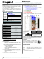
Commercial Power Enclosure Solutions and Main Lug Options — LCAP MODEL: LCAP44A
LCAP WITH MAIN LUG MODELS: LCAP44ALO/MLO/MCB
The VA-RUU-1 switch comes pre-installed in KIT.
The VA-EPC-DFS-1 switch is installed on site.
NOTE: Please see install sheets for emergency
switch applications.
EMR. SWITCH
VA-EPC-DFS-12OV(277V)
Order Se
p
arate
EMR. SWITCH
VA-RRU-1-12OV (277V)
LCA
P
-OPT-SWITCH
8-Port (4 standard and 4 POE)
Overview
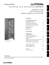
The Wattstopper® LCAP Series Commercial Enclosures ship with pre-configured
modular solutions. Load dimming and switching use the InFusion™ controllers
and switching products. The pre-configured designs save time in the Design
Center™ software and during the installation process.
The UL listed LCAP44A panels are adaptable to spaces that have mixed 0-10V,
and PWM loads and HV relay loads via the LVOS-0-10-PWM station. LCAP44A
connects to any controller over the local network for easy connection and
scalability.
Solution 1 – Parent-level Enclosure Models
Main Enclosure Description
LCAP44 44” Architectural Enclosure with hinged cover door
LCAP44A Panel
Configurations
(see KIT panel
part numbers
ordering key
last page)
Panel Upper Section:
1 to 2 LVOS-0-10-PWM stations
Panel Middle Section:
1 to 2 LVOS-0-10-PWM stations
Panel Lower Section:
1 to 2 LVOS-0-10-PWM stations
Panel Low-Voltage Section
Optional Parts Description
LCAP-OPT-SWITCH 8-Port (4 standard and 4 POE) Ethernet switch/power supply
VA-RRU-1-120V Emergency Shunt Relay - 120
V
VA-RRU-1-277V Emergency Shunt Relay - 277
V
Additional Parts Ordered Separately Description
VA-EPC-DFS-120V Emergency lighting surface mount switch 120V
VA-EPC-DFS-277V Emergency lighting surface mount switch 277V
Specifications
LCAP44A Specifications
Cabinet Dimensions HWD 44.5” x 24” x 4.575” / 113cm x 61cm x 11.6cm
Door Dimensions HWD 44.5” x 24” x 0.75” / 113cm x 61cm x 2cm
Panel Insert HWD 42” x 21” x 4.175” / 106.7cm x 53.3cm x 10.6cm
Weight Enclosure 41 lbs / 18.6 kg
Weight Door 20.7 lbs / 9.39 kg
Weight Panel Insert 23 lbs / 10.43 kg
Number of LVOS-0-10-PWM* stations Up to 6
Analog, 0-10DC/LV — Max. Outputs Up to 24
PWM, LV — Max. Outputs Up to 24
HV Relay 120-277 VAC — Max. Outputs Up to 24
Line Feeds (breakers) required 1 and Up
Enclosure Finish Galvanized Steel
Door Finish Black - Powder Coated
Cover vented, hinged
HV Wire copper wire, min of 80°C/176°F insulation
Ventilation maintained 36” front clearance
Ambient Operating Temp. 0-40°C / 32-104°F
Ambient Operating Humidity 5-95% non-condensing
UL, CUL, and CE listed yes
* See these install sheets for important information:
Low Voltage Output Station Lighting_LVOS-0-10-PWM-1
LCAP Enclosure Designs
LCAP Series Enclosure Facts.
Enclosures must be populated from left to right and top down.
o Blank positions cannot be left between lighting modules in Design
Center setup.
Enclosures are pre-configured and wired (to the extent possible) using
specific combinations of the following components. Installed components are
dependent on the enclosure design.
o Components using high voltage wiring.
Mixed high voltage wiring.
o Components using low voltage control signal wiring.
o Components using low voltage communication wiring.
o Components using high voltage and low voltage connections made
inside the enclosure.
The enclosure uses built-in barriers to separate high and low voltage wiring.
o Some designs include the barrier while other designs require the
barrier be added by the designer.
o High voltage barriers may be installed between 120V/240V/277V load
modules.
LCAP44A Enclosures only contain LVOS-0-10-PWM stations.
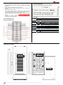
Enclosure Features / Parts
1. Enclosure can (includes door), order LCAP44 for can only.
2. Panel Insert (upper section).
a. Ground terminals, (notice terminals for all sections).
b. Wiring terminal blocks for upper section LVOS stations, (notice wiring
blocks for all sections if populated with LVOS stations).
i. Internal side pre-wired (see Wiring Block pg. 2).
ii. External side wired in field (see Wiring Block pg. 2).
c. Up to 2 LVOS-0-10-PWM stations (upper section)
3. Panel Insert (middle section).
a. Up to two additional LVOS-O-10-PWM stations.
4. Panel Insert (lower section).
a. Up to two additional LVOS-O-10-PWM stations.
5. Panel Insert (low-voltage section).
6. Enclosure cover with hinged/vented door allowing easy access when
servicing and proper ventilation for convection cooling process.
LCAP44A Panel Optional
Construction Parts See
Ordering Key,
last page.
Installation / Enclosure Mounting Instructions
Installation of LCAP products should be performed or supervised by a
Wattstopper factory representative. Installation and maintenance of high voltage
devices should only be performed by qualified and licensed personnel having
appropriate training and experience.
General Wiring
Drill proper size holes in can for running wires in and out of
the enclosure. Separate high and low voltage wire run
channels. All wire runs in and out of the enclosure should be
secured using 2-screw connectors or equivalent as shown at
the right . Proper conduit or equivalent wire channels
should be used according to local codes and regulations.
IMPORTANT SAFEGUARDS
READ AND FOLLOW ALL SAFETY INSTRUCTIONS
CAUTION: Turn Breakers OFF and check that no power is on at the AC
Terminal Boards when working in the enclosure or working on
lighting fixtures connected to the module’s loads, etc. Do not
allow trimmed wire cuttings to fall into enclosure components as
they may cause damage when power is restored. Damage from
this type of short will void the warranty.
Do not use outdoors.
Do not mount near gas or electric heaters.
Wattstoppe
r
®

WWW.LEGRAND.US/WATTSTOPPER - IS-00709-D Commercial Enclosure Solutions — MODEL: LCAP44/A & LCAP44/A + Main Lug page 2 of 8
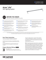
PANEL
BAC
K
VIEW
MULTI-VIEW
LCAP44A–
LCAP44A -
Architectural Panel -
A
uxiliary
*
LVOS-0-10-PWM -
select quantity: select -
(Leave blank for 0) 1, 2, 3, 4, 5, or 6
KIT PART NUMBERS:
LCAP44A-KIT
included
1
LCAP44A
panel
optional
1 COM-POE-SWITCH Ethernet sw
LCAP44A-1-KIT
included
1
LCAP44A
panel,
&
1
LVOS-0
-
10-PWM-
P
-1
with 1 pre-wired bloc
k
optional
1
COM-POE-SWITCH
Ethernet sw,
1
VA-RRU-1-120
V
or
VA-RRU-1
-
277
V
LCAP44A-2-KIT
included
1
LCAP44A
panel,
&
2
LVOS-0
-
10-PWM-
P
-1
with 2 pre-wired block
s
optional
1
COM
-
POE
-
SWITCH
Ethernet sw, 1 or 2
VA
-
RRU
-
1
-
120
V
or
VA
-
RRU
-
1
-
277
V
LCAP44A-3-KIT
included
1
LCAP44A
panel,
&
3
LVOS-0
-
10-PWM-
P
-1
with
3
pre-wired bloc
k
s
optional
1
COM
-
POE
-
SWITCH
Ethernet sw, 1 to 3
VA
-
RRU
-
1
-
120
V
or
VA
-
RRU
-
1
-
277
V
LCAP44A-4-KIT
included
1
LCAP44A
panel,
&
4
LVOS-0
-
10-PWM-
P
-1
with 4 pre-wired block
s
optional
1
COM
-
POE
-
SWITCH
Ethernet sw, 1 to 4
VA
-
RRU
-
1
-
120
V
or
VA
-
RRU
-
1
-
277
V
LCAP44A-5-KIT
included
1
LCAP44A
panel,
&
5
LVOS-0
-
10-PWM-
P
-1
with
5
pre-wired bloc
k
s
optional
1
COM
-
POE
-
SWITCH
Ethernet sw, 1 to 5
VA
-
RRU
-
1
-
120
V
or
VA
-
RRU
-
1
-
277
V
LCAP44A-6-KIT
included
1
LCAP44A
panel,
&
6
LVOS-0
-
10-PWM-
P
-1
with 6 pre-wired block
s
optional
1
COM
-
POE
-
SWITCH
Ethernet sw, 1 to 6
VA
-
RRU
-
1
-
120
V
or
VA
-
RRU
-
1
-
277
V
Do not mount enclosures in attics, garages, or crawlspaces, unless room is
properly conditioned to conform to ambient room temperature and humidity
requirements.
Mount enclosure a minimum of 18” from ceiling or floor.
National Electrical Code requires a minimum frontal clearance of 36” for the
enclosure.
Use screws provided for mounting.
If any emergency circuits are fed or controlled from this panel, it must be
located electrically where fed from a UPS, generator, or other guaranteed
source of power during emergency and power outage situations.
LISTED AS EMERGENCY LIGHTING EQUIPMENT – using an appropriate
label.
CAUTION: To avoid electrical
overload, total external connected
load should not exceed output rating.
SAVE THESE INSTRUCTIONS
Wire Block Terminal Close Up
Part Number Ordering Key
Design Center will generate part numbers automatically as the enclosures are
built. This key is for help creating manual orders if needed
LCAP44A Enclosure Multi-View
EMERGEN
C
Y CIRCUI
T
S

WWW.LEGRAND.US/WATTSTOPPER - IS-00709-F Commercial Enclosure Solutions — MODEL: LCAP44A & LCAP44ALO + Main Lug page 3 of 8
LCAP Panels with Main Lug Panel OPTION
LCAP44/A/LO/CB Panels with Main Lug Panel OPTION
Main Lug Circuit Breaker Option
The LCAPA and LCAPM series enclosures can be configured as a load feed
through panel (LCAP PANEL only) or as main lug panels with the addition of load
circuit breakers below the load control feed through compartment. Main lug
options can also contain a main breaker. The Main Lug option is available for the
LCAPALO and LCAPMLO/SLO series panels – see the LCAP32/44/M/S install
sheet. The circuit breaker options are based on the panel configuration, number
and type of loads,
and circuit breaker rating requirements. Once the main lug
panel and circuit breaker options are selected the panel is built and prewired* in
the factory and delivered to the project ready to be installed.
*NOTE: Panels with GFI breakers: GFI breakers are not installed or
pre-wired and are shipped separately.
Applications
The LCAP44A is designed for medium to large spaces requiring control of up to
24 low voltage PWM lighting circuits, 24 low voltage 010V DC lighting circuits,
and 24 120-277VAC relay lighting circuits. The built-in integration and networking
capabilities of the LCAP44A easily meet requirements in spaces needing multiple
types of lighting, and other automation integration systems using this panel.
Adding an Equinox 41 or 73 touchscreen to the project allows the facility
manager or end user to create, change, and manage scenes, schedules, and
user profiles.
Features
Modular LCAP load section; pre-configured solution from the factory. Just
connect line voltage and load wires.
Pre-configured Main Lug Panel solution options.
System is expandable using other LCAP series primary or secondary panels
and LCAP Main Lug / Circuit Breaker options.
Can be configured with emergency circuits for emergency lighting.
Connects to InFusion Controller system via Ethernet or Station Bus.
Up to 24 dry contact inputs; 12 of the contacts may be used for, system
powered, light sensors or occupancy sensors.
Dimmers have programmable start/stop and dimming curve adjustment
features to customize dimming linearity.
Simple programming from a single software solution - Design Center.
Adding one BACnet enabled controller to a system allows the entire system
to be controlled through BACnet.
Main Lug Panel options range from 18 to 36 circuits, 208-480V, and 10kAIC
to 65kAIC and may be configured with a main breaker option.
Setup In Design Center
Understanding LCAP and Main Lug panels:
LCAP panels with the Main Lug option is a larger enclosure that holds the
traditional LCAP components in the upper section of the enclosure and
includes a breaker section in the lower section of the enclosure.
LCAP panels with the Main Lug option are built in Design Center the same
way as standard LCAP panels. The only difference is the Main Lug option
has been selected. Follow the steps below to create an LCAP panel with the
Main Lug option selected.
1. In Design Center | Object Explorer select
Vantage Objects,
Enclosures, Commercial,
LCAP model,
o LCAP44A-KIT (Main Lug),
2. Right click in the enclosure and select
Populate to automatically add LVOS-PWM
stations in the enclosure or select LVOS-
PWM stations and drag into the enclosure
as wanted. (It is not possible to drag an
LVOS-PWM station below a blank station
position in an LCAP enclosure – fill
enclosure from left to right / top to bottom.
Notice that breakers are automatically
added to the Main Lug
section of the
enclosure as LVOS-PWM stations are
added.
3. It is possible to add additional breakers in
the Main Lug section by right clicking
below existing breakers and selecting Add
Breaker until the maximum number of
breakers allowed is reached.
4. Select the Main Lug section of the
enclosure and change the type to MCB to
add a Main Breaker option or leave as
MLO for standard load breakers only.
LCAP44ALO/MLO/MCB Series Specifications
Specifications LCAP44ALO/MLO LCAP44ALO/MCB
Cabinet / Panel Cover Dimensions HWD
68.0” x 24.0” x 4.75”
172.72cm x 60.96cm x 12.06cm
77.0” x 24.0” x 4.75”
195.58cm x 60.96cm x 12.06cm
Breakers Up to 18 Up to 36
Main Lug Panel Door Dimensions HWD
16” x 12.5” x 0.75”
40.64cm x 31.75cm x 1.9cm
23” x 19” x 0.75”
58.42cm x 48.26cm x 1.9cm
Weight Enclosure with Cover 165 - 175 lbs / 74.84 – 79.38 kg 170 - 180 lbs / 77.11 – 81.65 kg
LCAP Panel Door Dimensions HWD 40.5” x 16.0” x 0.75” / 102.87cm x 40.64cm x 1.9cm
Panel Insert HWD 42” x 21” x 4.175” / 106.7cm x 53.3cm x 10.6cm
Weight Panel Insert M-23 lbs. 10.43 kg
Number of LVOS-0-10-PWM* stations Up to 6
Analog, 0-10DC/LV — Max. Outputs Up to 24
PWM, LV — Max. Outputs Up to 24
HV Relay 120-277 VAC — Max. Outputs Up to 24
Enclosure Finish Galvanized Steel
Door Finish Black - Powder Coated
Cover vented, hinged
Wire copper wire, MIN. of 80°C / 176°F insulation
Ventilation maintained 36” front clearance
Ambient Operating Temp. 0-40°C / 32-104°F
Ambient Oper. Humidity 5-95% non-condensing
UL, CUL, and CE listed yes

WWW.LEGRAND.US/WATTSTOPPER - IS-00709-F Commercial Enclosure Solutions — MODEL: LCAP44A & LCAP44ALO + Main Lug page 4 of 8
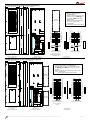
4 4 .75 ” ( 113 .6 6 5 c m ) 23.25” (59.055cm)
4 .5 ” ( 11.4 3 c m )24.0” (60.96cm)
68”
17 2 .7 2 c m
BUS DIAGRAMS
10 0 A M A I N L U GS
LCAP44-18PANEL
MAIN LUGS
WITH DOORS &
DEADFRONT REM
O
VED
LCAP44-18 PANEL
SURFACE TRIM
BOX 4 1/2” DEEP
WITH DOORS INS
T
ALLED
BARRIER
COMMUNICATION
CONDUIT
GROUND
BAR
CIRCUIT
BREAKERS
NEUTRAL
BAR
12 0 V/ 24 0 V 10 3 W
(10KAIC-22KAIC-65KAIC)
G
N
D
B
U
S
NEUTRAL
12
34
56
78
910
11 12
13 14
15 16
17 18
20
20
20
15
20
20
20
20
20
20
20
20
20
20
20
20
20
20
208Y/120V 30 4W
(10KAIC-22KAIC-65KAIC)
480Y/277V 30 4W
(14KAIC)
12
34
56
78
910
11 12
13 14
15 16
17 18
20
20
20
15
20
20
20
20
20
20
20
20
20
20
20
20
20
20
G
N
D
B
U
S
NEUTRAL
DIMMER
SECTION
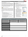
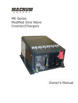
LCAP44ALO/MLO
1. Enclosure upper section for
LCAP44ALO Panel.
2. Enclosure lower section for up to 18
breakers. Select the Main Lug option
MLO option for (up to) 18, 20A
breakers.
3. Breaker section may be configured
for 4-wire or 3-wire power
configurations.
(See last page for breaker/order options)
LCAP44A
1. Start with the standard LCAP44A Panel.
2. Select the Main Lug option MLO or MCB.
Both LCAP44A MLO and MCB options come
with (up to) 18 or 36, 20A breaker
configurations.
The MCB option also comes with a 100A
main breaker for 18 breaker model or 225A
main breaker for 36 breaker model.
3. Finished LCAP44ALO/MLO enclosure – 68” H.
4. Finished LCAP44ALO/MCB enclosure – 77” H.
See additional specifications below
STANDARD LCAPA SERIES ENCLOSURES MAY BE CONFIGURED WITH MAIN LUG ENCLOSURES
Example LCAP44A configured with LCAP44ALO/MLO or MCB:
LCAP44ALO/MLO with Main Lug (up to 18 Breakers) Enclosure Multi-View
12 3 4
ADD THE MAIN
LUG MLO OPTION
CB OPTION
ADDS MAIN
BREAKER
OR ADD THE MAIN LUG
MCB OPTION
T
O CRE
A
TE AN
LCAP44ALO/ MLO
S
T
ANDARD
LCAP44A PANEL
OR CRE
A
TE AN
LCAP44ALO/ MCB
MLO
OPTION
MCB
OPTION

WWW.LEGRAND.US/WATTSTOPPER - IS-00709-F Commercial Enclosure Solutions — MODEL: LCAP44A & LCAP44ALO + Main Lug page 5 of 8
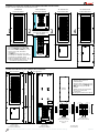
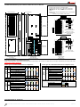
LCAP44-36PANEL
SURFACE MOUNT BOX
4-1/2” DEEP
WITH DOORS INSTALLED
77”
195.58cm
44.75” (113.665cm) 32.25” (81.915cm)
4.5” (11.43cm)24.0” (60.96cm)
LCAP44-36 PANEL
MAIN LUGS
WITH DOORS &
DEADFRONT REMOVED
BARRIER
COMMUNICATION
CONDUIT
GROUND
BAR
CIRCUIT
BREAKERS
NEUTRAL
BAR
DIMMER
SECTION
BREAKER
SECTION
BUS DIAGRAMS
225A MAINLUGS
20
20
20
20
20
20
20
20
20
20
20
20
20
20
20
12
34
56
78
910
11 12
13 14
15 16
17 18
19
29
27
25
23
21
20
30
28
26
24
22
3231
33
35
34
36
20
20
20
20
20
20
20
20
20
20
20
20
20
20
20
20
20
15
20
20
20
G
N
D
B
U
S
NEUTRAL
208Y/ 120V 30 4W
(10KAIC-22KAIC-65KAIC)
480Y/277V 30 4W
(14KAIC)
20
20
20
20
20
20
20
20
20
20
20
20
20
20
20
12
34
56
78
910
11 12
13 14
15 16
17 1 8
19
29
27
25
23
21
20
30
28
26
24
22
3231
33
35
34
36
20
20
20
20
20
20
20
20
20
20
20
20
20
20
20
20
20
15
20
20
20
G
N
D
B
U
S
NEUTRAL
12 0 V/ 2 4 0 V 10 3 W
(10KAIC-22KAIC-65KAIC)
LCAP44ALO/MLO (36 Breakers)
1. Enclosure upper section for LCAP44ALO Panel.
2. Enclosure lower section for up to 36 breakers. Select
the Main Lug option MLO option for (up to) 36, 20A
breakers.
3. Breaker section may be configured for 4-wire or 3-wire
power configurations.
(See last page for breaker/order
options)
LCAP44-18 PANEL
SURFACE MOUNT
BOX 4-1/2” DEEP WITH
DOORS INSTALLED
77”
195.58cm
4 4 .7 5 ” ( 113 .6 6 5 c m ) 32.25” (81.915cm)
4 .5 ” ( 11.4 3 c m )24.0” (60.96cm)
LCAP44-18 PANEL
MAIN BREAKER
WITH DOORS &
DEADFRONT REMOVED
BARRIER
COMMUNICATION
CONDUIT
GROUND
BAR
CIRCUIT
BREAKERS
NEUTRAL
BAR
BUS DIAGRAMS
100A MAIN BREAKER
3P
10 0 A
10 0 A
MAIN
12
34
56
78
910
11 12
13 14
15 16
17 18
20
20
20
20
20
15
20
20
20
20
20
20
20
20
20
20
20
NEUTRAL
G
N
D
B
U
S
BKR.
20
2P
10 0 A
10 0 A
MAIN
12
34
56
78
910
11 12
13 14
15 16
17 18
20
20
20
20
20
15
20
20
20
20
20
20
20
20
20
20
20
NEUTRAL
G
N
D
B
U
S
BKR.
20
208Y/120V 30 4W
(10KAIC-22KAIC-65KAIC)
480Y/277V 30 4W
(14KAIC-*35KAIC-*65KAIC)
*SERIES RATED
12 0 V/ 24 0 V 10 3 W
(10KAIC-22KAIC-65KAIC)
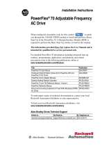
DIMMER
SECTION
LCAP44ALO/MCB
1. Enclosure upper section for
LCAP44ALO Panel.
2. Enclosure lower section for up to 18
breakers. Select the Main Lug type
and change to MCB to add a Main
Breaker option.
3. Breaker section may be configured
for 4-wire or 3-wire power
configurations.
(See last page for breaker/order options)
LCAP44ALO/MCB with Main Lug & Main Breaker Enclosure Multi-View
LCAP44ALO/MLO with Main Lug (up to 36 breakers) Enclosure Multi-View

WWW.LEGRAND.US/WATTSTOPPER - IS-00709-F Commercial Enclosure Solutions — MODEL: LCAP44A & LCAP44ALO + Main Lug page 6 of 8
LCAP44-36 PANEL
SURFACE MOUNT BOX
4-1/2” DEEP
WITH DOORS INSTALLED
77”
195.58cm
44.75” (113.665cm) 32.25” (81.915cm)
4.5” (11.43cm)24.0” (60.96cm)
LCAP44-36PANEL
MAIN BREAKER
WITH DOORS &
DEADFRONT REMOVED
BARRIER
COMMUNICATION
CONDUIT
GROUND
BAR
CIRCUIT
BREAKERS
NEUTRAL
BAR
BUS DIAGRAMS
100A - 225A
MAIN BREAKER
20
20
20
20
20
20
20
20
20
20
20
20
20
20
20
12
34
5
6
78
910
11 12
13 14
15 16
17 18
19
29
27
25
23
21
20
30
28
26
24
22
3231
33
35
34
36
20
20
20
20
20
20
20
20
20
20
20
20
20
20
20
20
20
15
20
20
20
NEUTRAL
G
N
D
B
U
S
3P
225A
225A
|
10 0 A
MAIN
BKR.
208Y/120V 30 4W
(10KAIC-22KAIC-65KAIC)
480Y/277V 30 4W
(14KAIC-*35KAIC-*65KAIC)
*SERIES RATED
20
20
20
20
20
20
20
20
20
20
20
20
20
20
20
12
34
5
6
78
910
11 12
13 14
15 16
17 18
19
29
27
25
23
21
20
30
28
26
24
22
3231
33
35
34
36
20
20
20
20
20
20
20
20
20
20
20
20
20
20
20
20
20
15
20
20
20
NEUTRAL
G
N
D
B
U
S
2P
225A
225A
|
10 0 A
MAIN
BKR.
12 0 V/ 24 0 V 10 3 W
(10KAIC-22KAIC-65KAIC)
DIMMER
SECTION
BREAKER
SECTION
LCAP44ALO/MCB (36 breaker)
1. Enclosure upper section for LCAP44ALO Panel.
2. Enclosure lower section for up to 36 breakers. Select the
Main Lug type and change to MCB to add a Main Breaker
option.
3. Breaker section may be configured for 4-wire or 3-wire power
configurations.
(See last page for breaker/order
options)
LCAP44ALO/MCB with Main Lug (up to 36 breakers) & Main Breaker Enclosure Multi-View
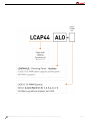
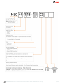
LCAP with Optional Main Lug Part Number Ordering Key
Design Center will generate LCAP44ALO/MLO/MCB part numbers automatically as the enclosures are built. This key is for help in understanding and creating orders in the
LCAP Quote Tool online ordering tool.
Breaker Types for LCAPALO/MLO/MCB Enclosure Configurations
CONFIGURATION FOR LCAP32
A
DDER - Branch Breakers Each, 1-Pole, 20
A
SIZE HEIGHT
BASE PANEL CONFIGURATION 10kAIC 14kAIC 22kAIC
35kAIC
65kAIC
18
circuits
100A
Bussing
56"
240V - MLO (Single Phase) BAB QHB
GHB
208V - MLO BAB QHB
GHB
480V - MLO GHB
65"
240V - MCB (Single Phase)(up to 100A, 65kAIC)
BAB*
208V - MCB (up to 100A, 65kAIC)
BAB*
480V - MCB (up to 100A, 35kAIC) GHB*
480V - MCB (up to 100A, 65kAIC)
GHB*
CONFIGURATION FOR LCAP44
A
DDER - Branch Breakers Each, 1-Pole, 20
A
SIZE HEIGHT
BASE PANEL CONFIGURATION 10kAIC 14kAIC 22kAIC
35kAIC
65kAIC
18
circuits
100A
Bussing
68"
240V - MLO (Single Phase) BAB QBH
GHB
208V - MLO BAB QBH
GHB
480V - MLO GHB
77"
240V - MCB (Single Phase)(up to 100A, 65kAIC)
BAB*
208V - MCB (up to 100A, 65kAIC)
BAB*
480V - MCB (up to 100A, 35kAIC) GHB*
480V - MCB (up to 100A, 65kAIC)
GHB*
Breaker Types for LCAPALO/MLO/MCB Enclosure Configurations (cont.)
CONFIGURATION FOR LCAP44 -
36 Breaker
A
DDER -
Branch Breakers Each, 1-Pole, 20
A
SIZE
HEIGHT
SIZE
HEIGHT
SIZE
HEIGHT
SIZE
HEIGHT
36
circuits
225A
Bussing
77"
240V -
MLO (Single Phase)
BAB
QBH
GHB
208V -
MLO
BAB
QBH
GHB
480V -
MLO
GHB
240V -
MCB (Single Phase)(up to 225A, 65kAIC)
BAB*
208V -
MCB (up to 225A, 65kAIC)
BAB*
480V -
MCB (up to 100A, 35kAIC)
GHB*
480V -
MCB (110A -
225A, 35kAIC)
GHB*
480V -
MCB (up to 100A, 65kAIC)
GHB*
480V -
MCB (100A -
225A, 65kAIC)
GHB*
* Breaker series rating when a main breaker option is selected
BREAKER RATING LEGEND (Single Phase)
MLO = Main Lug Option
Type BAB
10kAIC
MCB = Main Lug with Main Circuit Breake
r
Type QBH
22kAIC
Type GHB
65kAIC
LCAP Panel with Main Lug - Ordering Key

WWW.LEGRAND.US/WATTSTOPPER - IS-00709-F Commercial Enclosure Solutions — MODEL: LCAP44A & LCAP44ALO + Main Lug page 7 of 8

WWW.LEGRAND.US/WATTSTOPPER - IS-00709-F Commercial Enclosure Solutions — MODEL: LCAP44A & LCAP44ALO + Main Lug page 8 of 8
-
 1
1
-
 2
2
-
 3
3
-
 4
4
-
 5
5
-
 6
6
-
 7
7
-
 8
8


Legrand Architectural Dimming Panel - Auxiliary Guida d'installazione
- Tipo
- Guida d'installazione
in altre lingue
Altri documenti
-
LG ATNW36GMLS1 Guida d'installazione
-
 Lutron Electronics LCP128 Guida d'installazione
-
 GE current HORT170 Guida d'installazione
-
 Magnum Energy ME2000-20B Manuale del proprietario
-
 Allen-Bradley PowerFlex 70 Guida d'installazione
-
Powerware FerrUPS QFE Manuale utente
-
Eaton FerrUPS QFE Guida d'installazione
-
-
Eaton FERRUPS Guida d'installazione
-
Juniper Junos Space JA2500 Manuale utente


