
de Montageanleitung
fr Notice de montage
it Istruzioni per il montaggio
en Installation Instructions
nl Montage-instructies
es Instrucciones de uso

Sicherheitshinweise
Montage, Anschluss, Inbetriebnahme und
Reparatur dürfen nur von einer Fachkraft
durchgeführt werden. Diese Fachkraft kann
die geeignete Befestigung und Abluftführung
der Dunstabzugshaube bestimmen.Die Be-
festigung muss für das Gewicht der Dunst-
abzugshaube und die Belastung des Unter-
grunds geeignet sein. Die Auszugswerte der
mitgelieferten Dübel beachten.
Diese haben in Abhängigkeit vom Untergrund
folgende Werte: Dübel Ø10 mm: Beton B25
9,4 kN Mauerziegel Z20 5,2 KN Kalksand-
vollstein KSV20 4,8 KN Bei anderen unsiche-
ren Untergründen ist für die sichere Monta-
ge der Dunstabzugshaube ein Fachmann für
Bauangelegenheiten, z.B. ein Statiker oder
Architekt, zu befragen.
Verletzungsgefahr!
Scharfe Kanten können sich fertigungs-
bedingt im Haubenkörper befinden. Schutz-
handschuhe sind bei der Montage zu tragen.
Gefahr durch elektrischen Schlag
Die Netzspannung muss mit den Angaben
auf dem Typenschild übereinstimmen. Die-
ses befindet sich im Bereich der Filter im
Haubeninneren.Die Dunstabzugshaube nur
an eine vorschriftsmäßig installierte
Schutzkontaktsteckdose anschließen. Die
Steckdose muss nach der Montage leicht
erreichbar sein, um die Dunstabzugshaube
bei Bedarf von der Netzspannung trennen zu
können.
Bei Festanschluss (z.B. wenn eine entspre-
chende Steckdose nicht vorhanden ist) darf
die Dunstabzugshaube nur von einer Elektro-
fachkraft an die Netzspannung angeschlos-
sen werden. Für den Festanschluss muss die
Dunstabzugshaube an einen Einzel-
stromkreis mit Trennvorrichtung angeschlos-
sen werden. Als Trennvorrichtung gelten
Schalter mit einer Kontaktöffnung von
mindestens 3 mm und allpoligen Schalter,
z.B. LS-Schalter und Schütze. Vor den Ar-
beiten am elektrischen Anschluss der Dunst-
abzugshaube den Netzstromkreis/ die Netz-
stromkreise abschalten. Vor dem Bohren von
Befestigungslöchern sich vergewissern, dass
keine elektrische Leitungen durch das Boh-
ren beschädigt werden können. Der Elektro-
anschluss muss so vorbereitet werden, dass
die Dunstabzugshaube damit einfach ange-
schlossen werden kann. Örtliche Bestimmun-
gen müssen eingehalten werden.
Abluftführung (für Abluftbetrieb)
Die Abluft darf nicht in einen Schornstein
geführt werden, der für Abgase von Geräten
mit Brennstoffen (z.B. Gas) benutzt wird.
Behördliche Vorschriften für die Ableitung der
Abluft sind zu beachten. Der Abluftweg muss
so vorbeireitet werden, dass die Dunstab-
zugshaube damit einfach verbunden werden
kann. Der Abluftschlauch muss knickfrei ver-
legt sein.
Wenn die Dunstabzugshaube im Abluft-
betrieb gleichzeitig mit anderen raumluftab-
hängigen Feuerstätten (z.B. holz-, gas-, öl-
oder kohlebefeuerte Geräte) in einem Raum
betrieben werden, können tödliche
Verbrennungsgase durch einen entstehen-
den Unterdruck in den Raum zurückgeführt
werden. Der Bediener muß deshalb jederzeit
für eine ausreichende Zuluft sorgen. Der
Unterdruck im Raum darf nicht größer als 4
Pa (0,04mbar) sein.
Feuerstätte für feste Brennstoffe
Über einer Feuerstätte für feste Brennstoffe,
von der eine Brandgefahr (z.B. Funkenflug)
ausgehen kann, ist die Montage der Dunst-
abzugshaube nur dann zulässig, wenn die
Feuerstätte eine geschlossene, nicht ab-
nehmbare Abdeckung hat.
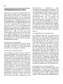
Mindestabstand zum Kochgerät
Die Geräte sind für den Deckenbündigen
Einbau konsipiert Um Kondensatbildung zu
verhindern muss eine Rückstauklappe direkt
am Luftaustritt außen montiert werden. Die
jeweils gültigen Einbauvorschriften und die
Einbauhinweise der Gas-Gerätehersteller
beachten.Über Gas-Kochstellen darf ein Min-
destabstand von 650 mm nicht unterschrei-
ten werden, wenn folgende Nennwärme-
de

belastungen (Hs) nicht überschritten werden:
Gas-Herde
Belastung einer Kochstelle max. 3,0 kW
Belastung aller Kochstellen max. 8,3 kW
Belastung des Backofens max. 3,9 kW
Gas-Kochmulden
Belastung einer Kochstelle max. 3,9 kW
Belastung aller Kochstellen max. 11,3 kW
Technische Änderungen vorbehalten!
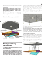
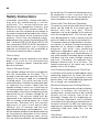
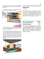
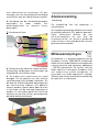
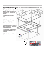
Montageanleitung
Anschluss oben
1. Geeignete Abluftführung bauseits in der
Decke vorbereiten.
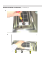
2. Positionen für Befestigungslöcher an der
Decke an Hand der vorgegebenen Aufhänge-
punkte am Haubenkörper übernehmen, und
mit geeignetem Bohrer bohren. Fehlende Ab-
messungen sind vom Modell abhängig und
müssen an der Haube gemessen werden. Auf
Mindestabstand zwischen Kochstelle und
Unterkante der Dunstabzugshaube achten.
(Löcher Ø10mm für die Befestigung der
Dunstabzugshaube)
Bitte auf eine mittige Anordnung der Dunst-
abzugshaube zu den Kochstellen achten.
3. Löcher bohren und entsprechenden Dü-
bel bündig einsetzen.
4. Stockschrauben soweit in die Dübel (Ø10
mm) einschrauben, dass noch ca. 20 mm her-
vorstehen. Gewindemuffen auf Stock-
schraube schrauben, Gewindestange mit
Stockschraube und kontern.
5. Dunstabzugshaube an den Gewindes-
tangen aufhängen und mittels Unterlegschei-
ben und Muttern locker befestigen (Empfeh-
lung: vorher Glasscheibe demontieren).
6. Dunstabzugshaube ausrichten (Montage-
maße prüfen) Muttern anziehen.
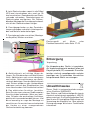
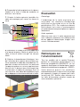
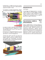
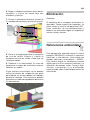
de
D
ämpfer
r
Glasscheibe
schwenkbar
Filter
Halog
en
Aufhängung
Scha
l
ter
EIN/AUS
+ Sensor
Zwischendecke

7. Abluftschlauch auf richtige Länge ab-
längen. Abluftschlauch anbringen und befes-
tigen, auf Knickfreiheit achten.
8. Den elektrischen Anschluss herstellen.
Beim Einsatz eines externen Gebläsemotors
Anschlusskabel verbinden.
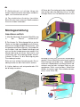
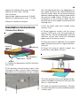
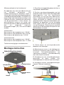
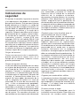
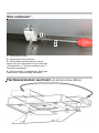
Montageanleitung
Anschluss seitlich
1. (Bei Abluftbetrieb) Geeignete Abluftführung
in der Wand vorbereiten.
2. Positionen für Befestigungslöcher an der
Decke an Hand der vorgegebenen Aufhänge-
punkte am Haubenkörper übernehmen, und
mit geeignetem Bohrer bohren. Fehlende Ab-
messungen sind vom Modell abhängig und
müssen an der Haube gemessen werden. Auf
Mindestabstand zwischen Kochstelle und
Unterkante der Dunstabzugshaube achten.
(Löcher Ø10mm für die Befestigung der
Dunstabzugshaube)
Bitte auf eine mittige Anordnung der Dunst-
abzugshaube zu den Kochstellen achten.
3. Löcher bohren und entsprechenden Dü-
bel bündig einsetzen.
4. Bevor die Dunstabzugshaube aufgehängt
wird, prüfen das der Abluftanschluss auf der
richtigen Seite sitz. Der Abluftanschluss kann
beliebig an allen vier Stirnseiten angeordnet
werden. Hierzu Metallfilter entnehmen und die
Befestigungsschrauben am Abdeckblech
entfernen. Abdeckblech mit Abluftstutzen ab-
nehmen und auf der richtigen Seite an vor-
gegebener Stelle anschrauben, Metallfilter
wieder einsetzen (ggf. Glasscheibe demon-
tieren siehe Seite 26).
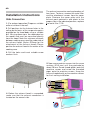
de

Entsorgung
Verpackung
Die Verpackung des Geräts ist recyclebar.
Als Verpackungsmaterial werden Karton und
Polyethylenfolie (PE) verwendet. Diese Ma-
terialien sind auf umweltgerechte und den
jeweiligen vor Ort geltenden Vorschriften
entsprechende Weise zu entsorgen.
Umwelthinweise
Dieses Gerät ist entsprechend der europäi-
schen Richtlinie 2002/96/EG
über Elektro- und Elektronikaltgeräte (waste
electrical and electronic equipment - WEEE)
gekennzeichnet, Die Richtlinie gibt den Rah-
men für eine EU-weit gültige Rücknahme und
Verwertung der Altgeräte vor. Über aktuelle
Entsorgungswege bitte beim Fachhändler
informieren.
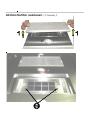
5. Jetzt Stockschrauben soweit in die Dübel
(Ø10 mm) einschrauben, dass noch ca. 20
mm hervorstehen. Gewindemuffen auf Stock-
schraube schrauben, Gewindestange mit
Stockschraube und kontern. Bei Decken-
bündiger Montage die Dunstabzugshaube di-
rekt an den Stockschrauben hängen.
6. Dunstabzugshaube an den Gewindes-
tangen aufhängen und mittels Unterlegschei-
ben und Muttern locker befestigen.
7. Dunstabzugshaube ausrichten (Montage-
maße prüfen) Muttern anziehen.
8. Abluftschlauch auf richtige Länge ab-
längen. Die Rändelmuttern am Abluftstutzen
lösen, Abluftstutzen nach ausen abnehmen
und mittels Schlauchklemme am Abluft-
schlauch befestigen. Nun den Abluftschlauch
samt Stutzen wieder an den Haubenkörper
anbringen und mit den Rändelmuttern von
innen verschrauben. Auf Knickfreiheit achten!
9. Den elektrischen Anschluss herstellen.
Beim Einsatz eines externen Gebläsemotors
Anschlusskabel verbinden. Wenn aus bauli-
chen Gründen die werkseitigen Aufhänge-
punkte nicht verwendet werden können, sind
diese bauseitig im zuge der Montage zu
verschliessen. Ansonsten kann es bei betrieb
der Haube zu einer unangenehmen
Geräuschentwicklung kommen.
de
Deckengerät mit Motor oder
Flachkanalanschluß, siehe Seite 27-29

Consignes de sécurité
Le montage, le branchement, la mise en
service et la réparation ont uniquement le droit
d’être effectués par un personnel spécialisé.
Ce personnel spécialisé peut déterminer la
fixation adéquate et le tracé de l’air
d’échappement des hottes aspirantes. La
fixation doit être adaptée au poids de la hotte
aspirante et à la charge du support. Les
valeurs de serrage des chevilles fournies sont
à observer. Selon le support, les chevilles ont
les valeurs suivantes : cheville diamètre 10
mm : béton B25 9,4 kN briques de
maçonnerie Z20 5,2 kN grès argilo-calcaire
KSV20 4,8 kN. En cas d’autres supports
faisant l’objet d’un doute, il est recommandé
de faire appel à un spécialiste en
construction, p. ex. à un staticien ou un
architecte, pour garantir le montage sûr de la
hotte aspirante.
Risque de blessures !
Le corps de la hotte peut présenter des arêtes
vives dues à la production. Des gants de
protection doivent être portés pour le
montage.
Risque de décharge électrique
La tension secteur doit correspondre aux
indications de la plaquette signalétique. Celle-
ci se trouve au niveau du filtre à l’intérieur de
la hotte. La hotte aspirante doit uniquement
être branchée à une prise de courant de
sécurité correctement installée. La prise doit
pouvoir être facilement accessible après le
montage pour pouvoir débrancher la hotte de
la tension secteur si besoin est. En cas de
branchement fixe (p. ex. si une prise de
courant adéquate n’est pas disponible), la
hotte aspirante doit uniquement être
raccordée à la tension secteur par un
électricien agréé. Pour un branchement fixe,
la hotte aspirante doit être branchée à un
circuit de courant individuel à dispositif de
coupure. Les interrupteurs avec une
ouverture de contact d’au moins 3 mm et les
interrupteurs à décommutation sur tous les
pôles, p. ex. les interrupteurs protecteurs de
lignes et les contacteurs peuvent être utilisés
comme dispositifs de coupure. Avant
d’effectuer des travaux sur le branchement
électrique de la hotte aspirante, le (les)
circuit(s) du courant secteur doit (doivent) être
mis hors service. Avant de percer des orifices
de fixation, veuillez vous assurer qu’aucune
conduite électrique ne risque d’être
endommagée par le perçage. Le
branchement électrique doit être préparé de
manière que la hotte aspirante puisse y être
facilement branchée. Les dispositions locales
sont à observer.
Guidage de l’air d’échappement (pour un
mode air échappement)
L’air d’échappement ne doit pas être guidé
dans une cheminée utilisée pour les gaz
d’échappement d’appareils fonctionnant avec
des matières combustibles (du gaz p. ex.).
Les prescriptions officielles pour l’évacuation
de l’air d’échappement sont à observer. La
voie de l’air d’échappement doit être préparée
de manière que la hotte puisse y être
facilement raccordée. Le flexible d’air
d’évacuation doit être posé sans coude.Des
gaz de combustion mortels dus à une
dépression peuvent être renvoyés dans la
pièce lors du fonctionnement simultané d’une
hotte aspirante en mode d’évacuation d’air
et d’autres foyers qui dépendent de l’air
ambiant (p. ex. appareils fonctionnant au bois,
au gaz, au fioul ou au charbon). C’est
pourquoi l’utilisateur doit à tout moment veiller
à une alimentation en air suffisante. La
dépression dans la pièce ne doit pas être
supérieure à 4 Pa (0,04 mbar).
Foyers pour matières combustibles solides
Le montage des hottes aspirantes au-dessus
d’un foyer à matières combustibles solides
d’où un danger peut émaner (p. ex. vol
d’étincelles) est uniquement autorisé lorsque
ce foyer est équipé d’un recouvrement
hermétique non amovible.
fr

Ecartement minimal par rapport à l’appareil
de cuisson
Les appareils sont conçus pour un montage
encastré au plafond. Un clapet
d’accumulation doit être directement monté
à l’extérieur sur la sortie de l’air pour éviter la
formation de condensat. Les prescriptions de
montage respectivement en vigueur ainsi que
les consignes de montage des fabricants
d’appareils fonctionnant au gaz doivent être
observées. L’écartement par rapport à des
foyers de cuisson au gaz ne doit pas être
inférieur à 650 mm au minimum lorsque les
charges thermiques nominales (Hs)
suivantes ne sont pas dépassées.
Gazinières: Charge d’un foyer max. 3,0 kW
Charge de tous les foyers max. 8,3 kW
Charge du four max. 3,9 kW
Tables de cuisson à gaz
Charge d’un foyer max. 3,9 kW
Charge de tous les foyers max. 11,3 kW
Sous réserve de modifications techniques
Notice de montage
Raccordement en haut
2. Reprendre les positions des orifices de
fixation sur le plafond à l’appui des points de
suspension marqués sur le corps de la hotte
et percer ces orifices avec un foret approprié.
Les dimensions manquantes dépendent du
modèle et doivent être mesurées sur la hotte.
Veiller à un écartement minimal entre le plan
de cuisson et l’arête inférieure de la hotte
aspirante. (Trous diamètre 10 mm pour la
fixation de la hotte aspirante).Faites en sorte
que la hotte aspirante soit centrée par rapport
au plan de cuisson.
3. Percer les trous et enfoncer les chevilles
appropriées.
4. Visser les vis dans les chevilles (diamètre
10 mm) de manière qu’elles ne se touchent
qu’à env. 20 mm en saillie. Visser les
manchons filetés sur les vis, visser la barre
filetée avec les vis et sécuriser le montage.
5. Suspendre la hotte aspirante sur les barres
filetées et la fixer à l’aide de rondelles et
d’écrous sans forcer.
6. Orienter la hotte aspirante (contrôler les
cotes de montage) puis serrer les écrous à fond.
1.Préparer un tracé d’air d’échappement
approprié dans le plafond.
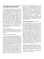
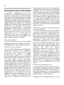
fr
Amortisseur
Vitre en verre
Filter
Halogêne
Suspension
Interrupteur Marche
-
Arrêt + capteur
Plafond
intermêdiair

7. Raccourcir le flexible d’air d’échappement
à la bonne longueur. Mettre en place ce fle-
xible, le fixer et veiller à ce qu’il ne soit pas
tordu.
8. Réaliser le branchement électrique. Lors
de l’utilisation d’un moteur de ventilateur ex-
terne, brancher le câble de raccordement.
Notice de montage
Raccordement latéral
1. (Lors d’un mode à air d’échappement)
Préparer le guidage de l’air d’échappement
approprié dans le mur.
2. Reprendre les positions des orifices de
fixation sur le plafond à l’appui des points de
suspension marqués sur le corps de la hotte
et percer ces orifices avec un foret approprié.
Les dimensions manquantes dépendent du
modèle et doivent être mesurées sur la hotte.
Veiller à un écartement minimal entre le plan
de cuisson et l’arête inférieure de la hotte
aspirante. (Trous diamètre 10 mm pour la
fixation de la hotte aspirante).Faites en sorte
que la hotte aspirante soit centrée par rapport
au plan de cuisson.
3. Percer les trous et enfoncer les chevilles
appropriées.
4. Avant de suspendre la hotte aspirante,
contrôler si le raccord de l’air d’échappement
se trouve du bon côté. Ce raccord peut être
disposé sur l’une des quatre faces frontales.
A cette fin, retirer le filtre en métal et les vis
de fixation sur la tôle de recouvrement. Retirer
la tôle de recouvrement avec la tubulure d’air
d’échappement vers l’intérieur et la visser au
bon endroit à l’emplacement prévu. Remettre
en place le filtre en métal. (seihe Seite 26)
5. Maintenant, visser les vis dans les chevilles
(diamètre 10 mm) de manière qu’elles ne se
touchent qu’à env. 20 mm en saillie. Visser
les manchons filetés sur les vis, visser la
barre filetée avec les vis et sécuriser le
montage. En cas de montage affleurant au
plafond, la hotte aspirante doit être
directement suspendue aux vis.
fr

6. Suspendre la hotte aspirante sur les barres
filetées et la fixer à l’aide de rondelles et
d’écrous sans forcer.
7. Orienter la hotte aspirante (contrôler les
cotes de montage) puis serrer les écrous à
fond.
Evacuation
Emballage
L’emballage de la hotte aspirante est
recyclable. Les matériaux d’emballage
consistent en du carton et en un film de
polyéthylène (PE). Ces matériaux doivent
être évacués sans nuire à l’environnement
et conformément aux prescriptions en vigueur
localement.
Hotte aspirante
Adressez-vous aussi à votre commune qui
vous indiquera comment vous débarrassez
de vos appareils domestiques usagés sans
nuire à l’environnement.
Remarques sur
l’environnement
Tous les modèles de la société Gutmann
portent un marquage conformément à la
directive européenne 2002/96/CE sur les
appareils électriques et électroniques (waste
electrical and electronic equipment – WEEE).
Cette directive prescrit les conditions
d’encadrement pour la reprise et le recyclage
des appareils usagés en vigueur dans tous
les pays de l’UE. Veuillez vous informer sur
les voies d’évacuation actuelles auprès de
votre revendeur spécialisé.
8. Raccourcir le flexible d’air d’échappement
à la bonne longueur. Mettre en place ce fle-
xible, le fixer et veiller à ce qu’il ne soit pas
tordu.
9. Réaliser le branchement électrique. Lors
de l’utilisation d’un moteur de ventilateur ex-
terne, brancher le câble de raccordement. Si,
pour des raisons constructives, les points de
suspension prévus en usine ne peuvent pas
être utilisés, ils doivent alors être fermés par
le client dans le cadre du montage. Dans le
cas contraire, une odeur désagréable risque
de se dégager au fonctionnement de la hotte.
fr

Avvertenze per la sicurezza
Il montaggio, il collegamento, la messa in
funzione e la riparazione devono essere
eseguiti esclusivamente da uno specialista.
Tale specialista può determinare il fissaggio
adeguato e la conduzione adatta dell’aria di
scarico della cappa d’aspirazione vapore. Il
fissaggio deve essere adeguato al peso della
cappa d’aspirazione vapore e al carico del
sottofondo. Osservare i valori d’estrazione dei
tasselli forniti in dotazione. Questi ultimi
presentano i seguenti valori, in funzione del
sottofondo: tasselli Ø 10 mm: calcestruzzo
B25 9,4 kN, mattoni Z20 5,2 KN arenaria
calcarea piena KSV20 4,8 KN. Per altri
sottofondi insicuri va interpellato uno
specialista edile, p.es. uno statico o un
architetto per garantire un montaggio sicuro
della cappa d’aspirazione vapore.
Pericolo di lesione!
Per motivi di fabbricazione nel corpo della
cappa possono trovarsi spigoli acuti. Per il
montaggio occorre indossare guanti protettivi.
Pericolo da scossa elettrica
La tensione della rete deve corrispondere alle
indicazioni riportate sulla targhetta.
Quest’ultima si trova nella zona dei filtri
all’interno della cappa. La cappa
d’aspirazione vapore va collegata
esclusivamente ad una presa con contatti di
protezione installata secondo le prescrizioni.
La presa deve essere facilmente
raggiungibile dopo il montaggio per potere
separare la cappa d’aspirazione vapore dalla
tensione della rete in caso di necessità. In
caso di collegamento fisso (p. es. quando non
è presente una presa corrispondente) la
cappa d’aspirazione vapore deve essere
collegata alla tensione della rete soltanto da
un elettricista specializzato. Per il
collegamento fisso la cappa d’aspirazione
vapore deve essere collegata ad un circuito
elettrico singolo con dispositivo di
separazione. Vengono considerati dispositivi
di separazione interruttori con un’apertura di
contatto di almeno 3 mm e con un interruttore
onnipolare, p. es. interruttore LS e contattori.
Prima di effettuare lavori sul collegamento
elettrico della cappa d’aspirazione vapore
disinserire il circuito/i circuiti della rete. Pri-
ma di praticare fori di fissaggio accertarsi che
non si possano danneggiare linee elettriche.
Il collegamento elettrico deve essere
preparato in modo tale che con esso la cappa
d’aspirazione vapore possa esservi collegata
facilmente. Occorre osservare le disposizioni
vigenti sul posto.
Conduzione dell’aria di scarico (per servizio
con aria di scarico)
L’aria di scarico non deve essere condotta in
un camino utilizzato per i gas di scarico di
apparecchi operati con combustibili (p. es.
gas). Vanno osservate le prescrizioni delle
autorità per la conduzione dell’aria di scarico.
Il percorso dell’aria di scarico deve essere
preparato in modo tale che la cappa
d’aspirazione vapore possa esservi collegata
facilmente. Il tubo flessibile dell’aria di scarico
deve essere posato senza pieghe. Se la
cappa d’aspirazione vapore viene operata in
servizio ad aria di scarico
contemporaneamente ad altri focolari
dipendenti dall’aria ambiente (p.es.
apparecchi operati a legna, a gas, a nafta o
a carbone) in un locale, potrebbero essere
ricondotti nel locale gas combusti mortali a
seguito di un’eventuale sottopressione. Per
questo motivo l’operatore deve assicurare in
qualsiasi momento che vi sia un sufficiente
apporto d’aria. La sottopressione nel locale
non deve essere maggiore di 4 Pa (0,04
mbar).
Focolari per combustibili solidi
Il montaggio della cappa d’aspirazione vapore
è consentito superiormente ad un focolare
per combustibili solidi da cui scaturisce un
pericolo d’incendio (p. es. scintille) solamente
a condizione che il focolare sia dotato di una
copertura chiusa, non rimovibile.
Distanza minima dall’apparecchio di cottura
it

Gli apparecchi sono concepiti per
l’installazione a raso di soffitto. Per evitare la
formazione di condensa occorre montare una
valvola di ristagno direttamente esternamente
all’uscita dell’aria. Vanno osservate le
prescrizioni d’installazione rispettivamente
valide e le avvertenze dei costruttori degli
apparecchi a gas. Superiormente ai punti
cottura a gas occorre osservare una distanza
minima di 650 mm se non vengono
oltrepassate le seguenti sollecitazioni di
calore nominale (Hs):
Forni a gas
Sollecitazione di un punto cottura max. 3,0 kW
Sollecitazione di tutti i punti cottura max. 8,3 kW
Sollecitazione del forno cottura max. 3,9 kW
Angoli cottura a gas
Sollecitazione di un punto cottura max. 3,9 kW
Sollecitazione di tutti i punti cottura max. 11,3 kW
Con riserva di apportare modifiche tecniche!
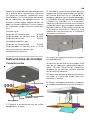
Istruzioni per il montaggio
Collegamento superiore
1. Preparare una guida appropriata dell’aria
di scarico nel soffitto presso il cliente.
2. Rilevare le posizioni per i fori di fissaggio
al soffitto sulla base dei punti di sospensione
previsti sul corpo della cappa e praticare i fori
con un trapano appropriato. Le misure
mancanti dipendono dal modello e devono
essere rilevate sulla cappa. Osservare la
distanza minima tra il punto di cottura e lo
spigolo inferiore della cappa d’aspirazione
vapore. (Fori Ø 10 mm per il fissaggio della
cappa d’aspirazione vapore). Osservare una
disposizione centrale della cappa
d’aspirazione vapore rispetto ai punti cottura.
3. Praticare i fori ed inserire a raso i relativi
tasselli.
4. Avvitare le morse a vite nei tasselli (Ø 10
mm) in misura tale che sporgano ancora di
circa 20 mm. Avvitare i manicotti filettati sulla
morsa a vite, l’asta filettata con la morsa a
vite e controserrare.
5. Appendere la cappa d’aspirazione vapore
alle aste filettate e fissare in modo allentato
mediante rondelle e dadi.
6. Orientare la cappa d’aspirazione vapore
(controllare le misure di montaggio), stringere i dadi.
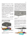
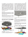
it
Ammortizzatore
Lastra di vetro
Filtro
Halogen
Sospensione
Interruttore ON/OFF
+ sensore
Solaio intermedio

7. Tagliare il tubo flessibile dell’aria di scarico
alla lunghezza giusta. Applicare il tubo
flessibile dell’aria di scarico, fare attenzione
ad evitare pieghe.
8. Realizzare il collegamento elettrico. In caso
di utilizzo di un motore di soffiante esterno
connettere il cavo di collegamento.
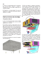
Istruzioni per il
montaggio
Collegamento laterale
1. Preparare una guida appropriata dell’aria
di scarico nella parete (in caso di servizio ad
aria di scarico).
2. Rilevare le posizioni per i fori di fissaggio
al soffitto sulla base dei punti di sospensione
previsti sul corpo della cappa e praticare i
fori con un trapano appropriato. Le misure
mancanti dipendono dal modello e devono
essere rilevate sulla cappa. Osservare la
distanza minima tra il punto di cottura e lo
spigolo inferiore della cappa d’aspirazione
vapore. (Fori Ø 10 mm per il fissaggio della
cappa d’aspirazione vapore).Osservare una
disposizione centrale della cappa
d’aspirazione vapore rispetto ai punti cottura.
3. Praticare i fori ed inserire a raso i relativi
tasselli.
4. Prima di appendere la cappa d’aspirazione
vapore controllare che il collegamento
dell’aria di scarico si trovi sul lato giusto. Il
collegamento dell’aria di scarico può essere
disposto a piacere su tutti e quattro i lati
frontali. Per fare ciò prelevare il filtro metallico
e rimuovere le viti di fissaggio dalla lamiera
di copertura. Staccare la lamiera di copertura
con il bocchettone dell’aria di scarico verso
l’interno ed avvitarla sul lato giusto al punto
previsto, reinserire il filtro metallico. (S. 26)
5. Ora avvitare le morse a vite nei tasselli (Ø
10 mm) in misura tale che sporgano ancora
di circa 20 mm. Avvitare i manicotti filettati
sulla morsa a vite, l’asta filettata con la morsa
a vite e controserrare. In caso di montaggio
a raso di soffitto appendere la cappa
d’aspirazione vapore direttamente alle mor-
se a vite.
it

6. Appendere la cappa d’aspirazione vapore
alle aste filettate e fissare in modo allentato
mediante rondelle e dadi.
7. Orientare la cappa d’aspirazione vapore
(controllare le misure di montaggio), stringere i dadi.
8. Tagliare il tubo flessibile dell’aria di scarico
alla lunghezza giusta. Applicare il tubo
flessibile dell’aria di scarico, fare attenzione
ad evitare pieghe.
9. Realizzare il collegamento elettrico. In caso
di utilizzo di un motore di soffiante esterno
connettere il cavo di collegamento.
Qualora per motivi costruttivi non possano
essere utilizzati i punti di sospensione di
fabbrica, questi vanno chiusi presso il cliente
nell’ambito del montaggio. Altrimenti
potrebbero prodursi rumori fastidiosi durante
il funzionamento della cappa.
Smaltimento
Imballaggio
L’imballaggio dell’apparecchio è riciclabile.
Come materiale d’imballaggio vengono
utilizzati cartone e foglia di polietilene (PE).
Questi materiali vanno smaltiti in modo
ecologico ed in ottemperanza alle rispettive
prescrizioni vigenti localmente.
Avvertenze relative
all’ambiente
Questo apparecchio è contrassegnato in
ottemperanza alla direttiva europea 2002/96/
CEE relativa agli apparecchi elettrici ed
elettronici vecchi (waste electrical and
electronical equipment - WEEE). Questa
direttiva definisce le condizioni di base per la
ripresa in consegna e lo sfruttamento di
apparecchi vecchi sull’intero territorio UE.
Informarsi presso il proprio concessionario
relativamente alle vie di smaltimento attuali.
it

Safety Instructions
Installation, connection, startup and repairs
may only be conducted by a service
technician. This service technician can
determine the appropriate fasteners and
exhaust air flow of the exhaust hood. The
fasteners must be suitable for the weight of
the exhaust hood and the load of the surface.
Note the resistance of the enclosed screw
anchors. These have the following values,
depending on the surface: Screw Anchor Ø10
mm: Concrete B25 9.4 kN Brick Z20 5.2 KN
lime sandstone KSV20 4.8 KN Consultant a
construction professional, e.g. a structural
engineer or architect for safe installation of
the exhaust hood into other surfaces.
Risk of Injury!
Sharp edges may be located on the hood
body as a result of the manufacturing
process. Protective gloves should be worn
during installation.
Risk of Electrical Shock!
The network voltage must be in accordance
with the information on the label. This is
located inside the hood, near the filter. Only
connect the exhaust hood to a standardly
installed outlet. The outlet must be easily
accessible after installation in order to be able
to separate the exhaust hood from the
network voltage if necessary. In the event of
a fixed connection (e.g. if a suitable outlet is
not available), the exhaust hood may only be
connected to the network voltage by an
electrician. The exhaust hood must be
connected to an individual electrical circuit
with an energy-isolating device for a fixed
connection. Switches with one contact
opening of at least 3 mm and all-pole
switches, e.g. LS switches and fuses are
deemed to be energy-isolating devices. Turn
off the network voltage current before working
on the electrical connection of the exhaust
hood. Before drilling fastener holes, ensure
that no electrical conduits will be damaged
by the drilling. The electrical connection must
be prepared in such a manner that the
exhaust hood can be easily connected to it.
Local conditions must be complied with.
Exhaust Air Flow (Exhaust Operation)
The exhaust may only be fed into a chimney
which can be used for the exhaust gas of
devices with fuel (e.g. gas). Official
regulations for the dissipation of the exhaust
must be complied with. The exhaust path
must be prepared in such a manner that the
exhaust hood can be easily connected to it.
The exhaust hose must be laid out in a mann-
er in which it is not bent. During simultaneous
operation of an exhaust hood for exhaust
purposes and other heat producing
appliances dependent upon the air in the
room (e.g. wood, gas or oil fueled devices) in
one room, deadly flammable gases could be
fed back into the room through negative
pressure. Therefore, the operator must
provide sufficient fresh air at all times. The
negative pressure in the room may not be
greater than 4 Pa (0 mbar).
Heat Producing Appliances for Fixed Fuel
Installation of the exhaust hood above a heat
producing appliance for fixed fuel which
carries a risk of fire (e.g. flying sparks) is only
permissible if the heat producing appliance
has a closed, non removable lid.
Minimum Distance from Cooking Devices
This device is designed for ceiling installation.
In order to prevent the formation of
condensation, a back flap must be installed
directly on the exterior side of the air
discharge. Comply with the respectively va-
lid installation regulations and installation
instruction of the gas device manufacturer. A
minimum distance of 650 mm above gas
cooking area cannot be deviated from if the
following rated heat loads (Hs) are not
exceeded:
Gas Stoves
Load of one cooking area max. 3.0 kW
en

Load of all cooking areas max. 8.3 kW
Load of the oven max. 3.9 kW
Gas Cooktops
Load of one cooking area max. 3.9 kW
Load of all cooking areas max. 11.3 kW
Subject to technical changes!
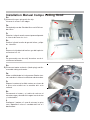
Installation Instructions
Connection Above
1. Prepare an appropriate exhaust airflow in
the ceiling.
2. Drill positions for the fastener holes in the
ceiling on the basis of the suspension points
provided on the hood body using a suitable
drill. Missing dimensions are dependent on
the model and must be measured directly
from the hood. Note the minimum distance
between cooking areas and the underside of
the exhaust hood. (Holes Ø10mm for the
attachment of the exhaust hood) Please
position the exhaust hood in the center of the
cooking area.
3. Drill the holes and insert suitable screw
anchors flush.
4. Screw machine screws into the screw
anchors (Ø10 mm) until they protrude by
about 20 mm. Screw thread guides onto the
machine screws and screw the threaded
pipes onto the machine screws.
5. Hang the exhaust hood on the threaded
pipes and loosely fasten it using the washers
and nuts.
6. Align the exhaust hood (inspect the
installation) and tighten the nuts.
en
7. Cut the exhaust hose to the proper length.
Attach and tighten the exhaust hose, be sure
that it is free of bends.
8. Create the electrical connection. Connect
an extension cable if an external blower motor
is to be used.
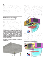
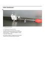
Damper
Glass Pane
Filter
Halogen
Suspension
On/Off Switch +
Sensor
Interior
Liner

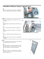
Installation Instructions
Side Connection
1. (For exhaust operation) Prepare a suitable
exhaust airflow in the wall.
2. Drill positions for the fastener holes in the
ceiling on the basis of the suspension points
provided on the hood body using a suitable
drill. Missing dimensions are dependent on
the model and must be measured directly
from the hood. Note the minimum distance
between cooking areas and the underside of
the exhaust hood. (Holes Ø10mm for the
attachment of the exhaust hood) Please
position the exhaust hood in the center of the
cooking area.
3. Drill the holes and insert suitable screw
anchors flush.
4. Before the exhaust hood is suspended,
make sure that the exhaust connection is
located on the correct side.
The exhaust connection can be placed on all
four faces. To do so, remove the metal filter
and the attachment screws from the cover
plate. Remove the cover plate with the
exhaust posts pointed in and attach to the
proper side in the indicated position, replace
the metal filter. S 26.
en
5. Now screw machine screws into the screw
anchors (Ø10 mm) until they protrude by
about 20 mm. Screw thread guides onto the
machine screws and screw the threaded
pipes onto the machine screws. Hang the
exhaust hood directly on the machine screws
for flush ceiling installation.

6. Hang the exhaust hood on the threaded
pipes and loosely fasten it using the washers
and nuts.
7. Align the exhaust hood (inspect the
installation) and tighten the nuts.
Disposal
Packaging
The packaging of the exhaust hood is
recyclable. Cardboard and polyethylene foil
(PE) are used as packaging materials. The-
se materials are environmentally compliant
and should be disposed of as per the valid
regulations of the respective location.
Environmental
Instructions
This device is labeled as per European
Directive 2002/96/EG on Waste Electrical and
Electronic Equipment (WEEE). This guideline
provides the basic conditions valid for the EU-
wide return and recycling of old appliances.
Please consult your dealer for the current
disposal methods.
en
8. Cut the exhaust hose to the proper length.
Attach and tighten the exhaust hose, be sure
that it is free of bends.
9. Create the electrical connection. Connect
an extension cable if an external blower motor
is to be used. If the device side suspension
points cannot be used for construction
reasons, these must be sealed on the wall
side during installation. Otherwise unpleasant
sounds can develop while the hood is in
operation.

Veiligheidsinstructies
Montage, aansluiting, inbedrijfstelling en
herstelling mogen uitsluitend door een
vakkundig geschoolde arbeidskracht
doorgevoerd worden. Deze vakkundig
geschoolde arbeidskracht kan de geschikte
bevestiging en afzuiggeleiding van de
afzuigkap bepalen. De bevestiging moet voor
het gewicht van de afzuigkap en de belasting
van de ondergrond geschikt zijn.
Uittrekwaarden van de bijgeleverde
dookpennen in acht nemen. Afhankelijk van
de ondergrond hebben ze volgende waarden:
dookpen Ø10 mm: beton B25 9,4 kN
metselsteen Z20 5,2 KN massieve
kalkzandsteen KSV20 4,8 KN. Bij een ande-
re onveilige ondergrond moet er voor een
betrouwbare montage van de afzuigkap op
een vakman voor bouwaangelegenheden,
bijvoorbeeld een staticus of een architect,
beroep gedaan worden.
Gevaar voor verwondingen!
Scherpe kanten kunnen zich omwille van de
fabricage in het kaplichaam bevinden. Bij de
montage dienen er beschermende
handschoenen gedragen te worden.
Gevaar door elektrische schok
De netspanning moet met de op het
typeaanduidingplaatje vermelde gegevens
overeenstemmen. Dit bevindt zich in het
bereik van de filters in het binnenste gedeelte
van de kap. De afzuigkap uitsluitend op een
volgens de voorschriften geïnstalleerde
veiligheidswandcontactdoos aansluiten. De
contactdoos moet na de montage
gemakkelijk bereikbaar zijn om de afzuigkap,
indien gewenst, van de netspanning te
kunnen verbreken. Bij een vaste aansluiting
(bijvoorbeeld als een corresponderende
contactdoos niet beschikbaar is) mag de
afzuigkap uitsluitend door een vakkundig
geschoolde elektricien op de netspanning
aangesloten worden. Voor de vaste
aansluiting moet de afzuigkap op een
afzonderlijke stroomkring met
scheidingsinrichting aangesloten worden. Als
scheidingsinrichting gelden schakelaars met
een contactopening van minstens 3 mm en
schakelaars met alle polen, bijvoorbeeld LS-
schakelaars en schuiven. Vóór de
werkzaamheden aan de elektrische
aansluiting van de afzuigkap de
netstroomkring(en) uitschakelen. Vóór het
boren van bevestigingsgaten zich ver-
gewissen dat er door het boren geen elektri-
sche leidingen beschadigd kunnen worden.
De elektrische aansluiting moet zodanig
voorbereid worden, dat de afzuigkap
daardoor gemakkelijk aangesloten kan wor-
den. Lokale bepalingen moeten nageleefd
worden.
Afzuiggeleiding (voor afzuigmodus)
De uitlaatlucht mag niet in een schoorsteen
geleid worden, die voor uitlaatgassen van
apparaten met brandstoffen (bijvoorbeeld
gas) gebruikt wordt. Voorschriften van
overheidswege voor de afvoer van de
uitlaatlucht dienen in acht genomen te wor-
den. Het afzuigtraject moet zodanig
voorbereid worden, dat de afzuigkap
daardoor gemakkelijk verbonden kan wor-
den. De afzuigslang moet zonder knikken
geïnstalleerd zijn. Als de afzuigkap in de
afzuigmodus gelijktijdig met andere van de
kamerlucht afhankelijke stookplaatsen
(bijvoorbeeld met hout, gas, olie of steenkool
gestookte apparaten) in een lokaal bediend
wordt, kunnen er dodelijke verbrandings-
gassen door een ontstaande onderdruk naar
het lokaal geleid worden. De operator moet
daarom op ieder moment voor voldoende
luchttoevoer zorgen. De onderdruk in het lok-
aal mag niet hoger dan 4 Pa (0,04mbar) zijn.
Stookplaats voor vaste brandstoffen
Door middel van een stookplaats voor vaste
brandstoffen, waarvan er brandgevaar
(bijvoorbeeld het rondvliegen van vonken)
kan uitgaan, is de montage van de afzuigkap
slechts toegelaten als de stookplaats een
gesloten, niet verwijderbare afdekking heeft.
nl

Minimumafstand tot het kooktoestel
De apparaten zijn voor een inbouw vlak aan
het plafond ontworpen. Om
condensaatvorming te voorkomen, moet er
vlak aan de luchtuitlaat aan de buitenzijde een
stuwklep gemonteerd worden. De telkens van
toepassing zijnde inbouwvoorschriften en de
inbouwinstructies vanwege de fabrikanten
van de gastoestellen in acht nemen. Via
gaskookplaten mag er niet onder een
minimumafstand van 650 mm gebleven wor-
den als volgende nominale
warmtebelastingen (Hs) niet overschreden
worden:
Gasfornuizen
Belasting van één kookplaat max. 3,0 kW
Belasting van alle kookplaten max. 8,3 kW
Belasting van de bakoven max. 3,9 kW
Gaskookpannen
Belasting van een kookplaat max. 3,9 kW
Belasting van alle kookplaten max. 11,3 kW
Technische wijzigingen voorbehouden!
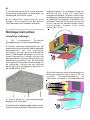
Montage-instructies
Aansluiting bovenaan
nl
1. Geschikte afzuiggeleiding door de klant in
het plafond voorbereiden.
2. Posities voor bevestigingsgaten aan het
plafond aan de hand van de vooraf bepaalde
ophangpunten aan het kaplichaam
overnemen en met geschikt boortoestel
boren. Ontbrekende afmetingen zijn van het
model afhankelijk en moeten aan de kap
gemeten worden. Op minimumafstand tussen
kookplaat en onderkant van de afzuigkap
letten (gaten Ø10 mm voor de bevestiging
van de afzuigkap). Gelieve op een centrale
opstelling van de afzuigkap ten opzichte van
de kookplaten te letten.
3. Gaten boren en corresponderende
dookpen vlak inbrengen.
4. Stokschroeven zover in de dookpennen
(Ø10 mm) inschroeven, dat er nog ca. 20 mm
uitsteekt. Schroefdraadmoeren op
stokschroef schroeven, schroefdraadstang
met stokschroef counteren.
5. Afzuigkap aan de schroefdraadstangen
ophangen en door middel van
onderlegplaatjes en moeren losjes bevestigen.
6. Afzuigkap uitlijnen (montageafmetingen
nagaan). Moeren aandraaien.
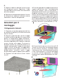
Demper
Glasruit
Filter
Halogeen
Afhanginrichting
Schakelaar Aan/uit
+ Sensor
Verlaagd plafond

7. Afzuigslang op correcte lengte brengen.
Afzuigslang aanbrengen en bevestigen, op
afwezigheid van knikken letten.
8. De elektrische aansluiting tot stand
brengen. Bij het gebruik van een externe
ventilatormotor aansluitkabel verbinden.
Montage-instructies
ansluiting zijdelings
1. (Bij afzuigmodus) Geschikte
afzuiggeleiding in de wand voorbereiden.
2. Posities voor bevestigingsgaten aan het
plafond aan de hand van de vooraf bepaalde
ophangpunten aan het kaplichaam
overnemen en met geschikt boortoestel
boren. Ontbrekende afmetingen zijn van het
model afhankelijk en moeten aan de kap
gemeten worden. Op minimumafstand tussen
kookplaat en onderkant van de afzuigkap
letten (gaten Ø10 mm voor de bevestiging van
de afzuigkap). Gelieve op een centrale
opstelling van de afzuigkap ten opzichte van
de kookplaten te letten.
3. Gaten boren en corresponderende
dookpen vlak inbrengen.
4. Voordat de afzuigkap opgehangen wordt,
nakijken dat de afzuigaansluiting aan de juiste
zijde gesitueerd is. De afzuigaansluiting kan
willekeurig aan al de vier voorzijden
aangebracht worden. Hiervoor metalen filter
verwijderen en de bevestigingsschroeven aan
de afdekplaat verwijderen. Afdekplaat met
afzuigmof langs binnen afnemen en aan de
juiste zijde op de voorbestemde plaats
vastschroeven, metalen filter terug
aanbrengen. S 26.
5. Nu stokschroeven zover in de dookpennen
(Ø10 mm) schroeven, dat er nog ca. 20 mm
uitsteekt. Schroefdraadmoeren op
stokschroef schroeven, schroefdraadstang
nl
La pagina si sta caricando...
La pagina si sta caricando...
La pagina si sta caricando...
La pagina si sta caricando...
La pagina si sta caricando...
La pagina si sta caricando...
La pagina si sta caricando...
La pagina si sta caricando...
La pagina si sta caricando...
La pagina si sta caricando...
La pagina si sta caricando...
La pagina si sta caricando...
La pagina si sta caricando...
La pagina si sta caricando...
La pagina si sta caricando...
La pagina si sta caricando...
-
 1
1
-
 2
2
-
 3
3
-
 4
4
-
 5
5
-
 6
6
-
 7
7
-
 8
8
-
 9
9
-
 10
10
-
 11
11
-
 12
12
-
 13
13
-
 14
14
-
 15
15
-
 16
16
-
 17
17
-
 18
18
-
 19
19
-
 20
20
-
 21
21
-
 22
22
-
 23
23
-
 24
24
-
 25
25
-
 26
26
-
 27
27
-
 28
28
-
 29
29
-
 30
30
-
 31
31
-
 32
32
-
 33
33
-
 34
34
-
 35
35
-
 36
36


Gutmann ESTRELLA Installation Instructions Manual
- Tipo
- Installation Instructions Manual
- Questo manuale è adatto anche per
in altre lingue
- English: Gutmann ESTRELLA
- français: Gutmann ESTRELLA
- español: Gutmann ESTRELLA
- Deutsch: Gutmann ESTRELLA
- Nederlands: Gutmann ESTRELLA
Altri documenti
-
 Opera CLARO CCL086B1 Ceiling Unit Extractor Hood Manuale utente
-
V-ZUG 493 Guida d'installazione
-
-
Siemens LC957KB70/01 Manuale utente
-
Electrolux DA5-55VI1 Manuale utente
-
Electrolux DCL5530BR Manuale utente
-
Bauknecht DA2755W Manuale utente
-
Siemens LF957GA70/01 Manuale del proprietario
-
-
Kampmann KaCool W Guida d'installazione
