Yamaha MT2X Manuale del proprietario
- Categoria
- Microfoni
- Tipo
- Manuale del proprietario
Questo manuale è adatto anche per

®
YAMAHA
AUTHORIZED
PRODUCT MANUAL
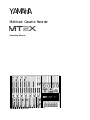
Multitrack Cassette Recorder

YAMAHA
Multitrack Cassette Recorder
Operating Manual

Congratulations on your choice of the Yamaha MT2X Multitrack Cassette
Recorder. The Yamaha MT2X Multitrack Cassette Recorder is a complete
multitrack recording package which elegantly integrates a high-performance
six-channel mixer and dual-speed 4-track cassette recorder. It is fully com-
patible with advanced MIDI tape synchronization applications, and accepts
an optional plug-in YMC2 MIDI Converter that makes MIDI timing signals
from any appropriate MIDI device usable for synchronization With a full
complement of carefully planned features and functions, the MT2X is a
musical instrument in its own right. It can vastly expand your creative
scope.
To take full advantage of the outstanding features and performance
capabilities of the MT2X, we urge to read this owner’s manual thoroughly.
CONTENTS
BEFORE OPERATION
................................................................. 2
PLEASE NOTE THE FOLLOWING PRECAUTIONS
...................... 2
THE DIFFERENCE BETWEEN TRACKS AND CHANNELS
............ 3
WHAT IS A MULTITRACK CASSETTE RECORDER? .................. 3
THE CONTROLS AND THEIR FUNCTIONS
.................................... 4
MIXER SECTION ................................................................... 4
RECORDER SECTION
............................................................
8
METER AND MONITOR SECTION
...........................................
10
CONNECTOR SECTION
..........................................................
12
CONNECTION EXAMPLE
............................................................
14
ABOUT CASSETTE TAPES
.........................................................
15
MULTITRACK RECORDING TECHNIQUES
....................................
16
ONE EXAMPLE OF A MULTITRACK RECORDING PROCESS
.......
16
BEFORE RECORDING
.............................................................
16
MULTITRACK RECORDING
....................................................
17
USING CHANNELS 5 AND 6 ..................................................
33
SYNC-RECORDING
.................................................................... 34
FOR MAXIMUM
PERFORMANCE OF YOUR
MT2X ........................ 35
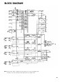
BLOCK DIAGRAM
.....................................................................
36
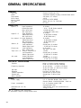
GENERAL SPECIFICATIONS
.......................................................
37
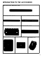
INTRODUCTION TO THE ACCESSORIES
......................................
38
SERVICE
..................................................................................
39
1

BEFORE OPERATION
n
PLEASE NOTE THE FOLLOWING PRECAUTIONS:
ABOUT CASSETTE TAPE
This unit is designed to be used only with Chrome-
position tape, and will not work properly with Ferri-
chrome tape formulations. CrO
2 tape (Bias: HIGH;
EQ: 70µs) should be used. Also, the use of C-120
tapes is not recommended because they exhibit
poorer performance, and can be the cause of equip-
ment failure.
ABOUT dbx
In order to get proper sound reproduction, set the dbx
switch ON when playing back tapes recorded with
dbx on, and keep it OFF when playing back tapes
recorded without dbx.
*dbx and the dbx mark are trademarks of dbx in-
corporated.
*The dbx system has been manufactured under
license of dbx Incorporated.
CHECK YOUR AC POWER SUPPLY
PRECAUTION AGAINST LIGHTNING
In the event of lightning or electrical storms, unplug
the AC power cord as soon as possible to avoid poten-
tial damage.
DO NOT OPEN THE CABINET
To avoid electrical shock or damage to the unit, do
not open the cabinet and tamper with the parts or
circuits inside.
CONNECTING OTHER EQUIPMENT
Make sure the power switch is OFF and the input
fader is all the way down when connecting other
equipment.
MOVING THE UNIT
To prevent shorts or breakage, make sure all connec-
tion cords have been removed from the unit before
moving it.
CLEANING THE CABINET
Make sure that your local AC mains voltage matches
the voltage specified on the bottom panel of the
MT2X — check this BEFORE plugging in and turning
on your MT2X! For General models equipped with a
voltage selector, make sure the voltage selector is set
to match your local line voltage.
Do not clean the unit with benzene or other power-
ful solvents, and avoid the use of aerosol insecticides
near the unit. Clean the unit only with a soft, dry
cloth.
The rated supply voltage for U.S. and Canadian
models is 120 VAC. The General model is rated for
use with 110/120/220/240 VAC supplies (the bottom-
panel voltage selector is factory preset to
220 volts).
FCC CERTIFICATION (USA)
This equipment generates and uses radio frequen-
cy energy and if not installed and used properly, that
is, in strict accordance with the manufacturer’s
instructions, may cause interference to radio and
television reception. It has been type tested and
found to comply with the limits for a Class B com-
puting device in accordance with the specifications
in Subpart J of Part 15 of FCC Rules, which are
designed to provide reasonable protection against
such interference in a residential installation. How-
ever, there is no guarantee that interference will not
occur in a particular installation. If this equipment
does cause interference to radio or television recep-
tion, which can be determined by turning the equip-
ment off and on, the user is encouraged to try to
correct the interference by one or more of the follow-
ing measures:
Reorient the receiving antenna.
Relocate the computer with respect to the receiver.
Move the computer away from the receiver.
Plug the computer into a different outlet so that
computer and receiver are on different branch cir-
cuits.
If necessary, the user should consult the dealer
or an experienced radio/television technician for ad-
ditional suggestions. The user may find the follow-
ing booklet prepared by the Federal Communications
Commission helpful:
“How to identify and Resolve Radio-TV inter-
ference problems”.
This booklet is available from the U.S. Government
Printing Office, Washington, DC 20402, Stock No.
004-000-00345-4.
2

n
THE DIFFERENCE BETWEEN TRACKS AND CHANNELS
The words “track” and “channel” are often confused. In order to properly operate this unit, it is necessary to under-
stand the meanings of these terms.
TRACK:
The “band” on the tape itself where a certain signal is
recorded. The tape inside a cassette has four different
tracks, enabling the recording of four distinct signals.
For conventional recordings, there are two tracks (stereo
left and right) on each side of the tape.
CHANNEL:
The route of a signal input or output. In the input side,
this unit has six INPUT channels and two AUX channels.
The output side consists of one stereo channel (made
up of two mono channels) and an AUX channel.
n
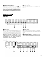
WHAT IS A MULTITRACK CASSETTE RECORDER?
The difference between the MT2X multitrack cassette recorder and a conventional stereo cassette deck is shown
below.
CONVENTIONAL STEREO CASSETTE DECK
The diagram shows how a conventional stereo cassette
deck records and plays back music. The four tracks on
a cassette tape represent the left and right (for stereo)
For right channel track
sound for each side of the tape. The MT2X uses these
For left channel track
four tracks for single-direction recording and playback
For left channel track on the B side
on only one side of a cassette tape.
For right channel track on the B side
Conventional stereo cassette recorders always record
For right channel track on the A side
and play back in the same mode, with the tape side
For left channel track on the A side
(direction) determining which two tracks will be used.
These recorders do not allow separate selection of tracks
for recording and playback.
MT2X MULTITRACK CASSETTE RECORDER
For channel 3
For channel 4
Multitrack recorders, however, allow you to record or
playback tracks separately as you choose. This enables
a degree of recording and playback freedom not possible
with conventional cassette recorders.
Track for channel 4 (track 4)
Track for channel 3 (track 3)
Track for channel 2 (track 2)
Track for channel 1 (track 1)
3

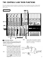
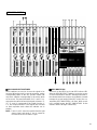
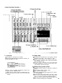
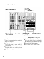
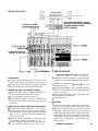
THE CONTROLS AND THEIR FUNCTIONS
This section explains the names and functions of all the knobs, sliders, and switches for the mixer, recorder, meter/
monitor, and connector sections. Familiarize yourself with them in order to take full advantage of the MT2X’s ver-
satile functions.
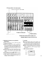
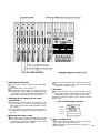
MIXER SECTION
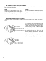
INPUT SELECTOR SWITCHES
These three-position switches are provided on input
channels 1 through 4. Position them according to the
operation to be performed. Note that input channels 5
TAPE:
Set the switch to this position to playback
material which has already been recorded on
this channel. Channels 1–4 correspond to
tracks 1–4 on the tape.
MIC/LINE: Only input channels 1 and 2 accept
microphone input. This position on the chan-
nel 3 and 4 inputs is simply marked “LINE”.
Set this switch to the proper position when
the output of a microphone, keyboard instru-
ment, or electric guitar is connected to the
corresponding input jack on the front panel.
and 6 only accept line input.
OFF:
Be sure to set the switch to this position
when the channel is not being used, or when
you don’t want to playback material already
recorded on the track. Although sliding the
input fader to the “O” position will stop
the signal, it’s a good idea to also set the
switch to OFF.
4
instrument
to channel
1 or 2
Sounds already
recorded
Microphone or

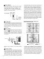
GAIN CONTROLS
These controls adjust the input level of the channel
to match the output level of a microphone or instru-
ment connected to input jack of channel 1 or 2.
Control from
-10dB to -50dB is possible. Adjust
the output level of the microphone or instrument as
outlined in its instruction booklet.
Low output source,
such as a microphone
High out-
put source,
such as an
electronic
keyboard
CLIP INDICATOR
These LED indicators are provided on channels 1 and 2.
If a CLIP LED lights, the input level to that channel is
too high and is causing clipping distortion. The situation
must be remedied by reducing the setting of the corres-
ponding GAIN control, or by reducing the output level
of the source.
INPUT FADERS
These controls adjust the volume of the signal input, and
send it to the equalizer. Each control is used for set-
ting the sound level of its channel when mixing it with
the signals of other channels. Position “7” on the scale
is considered ideal for the lowest noise and distortion
characteristics.
L R AUX
Input signal
Pan pot
Equalizer controls AUX control
FREQUENCY (Hz)
Be sure to set the control to “0” for channels not being
used.
EQUALIZER CONTROLS
These controls are used to adjust the tonal character-
istics of the input signal, or the channel output during
playback of previously recorded material. The LO (low)
controls adjust the frequencies centering around 100Hz,
while the HI (high) controls adjust the frequencies center-
ing around 10KHz, with a 10dB boost or cut range for
both controls. Use of these equalizer controls will help
5
you to get the type of sound you desire, and allow you
to bring the sound “forward”, “clean up” unclear sounds,
and “push down” sounds at annoying frequencies.
In order to properly use these equalizers, it’s important
to understand the frequency response characteristics
of various musical instruments. This is particularly true
when trying to “change” the sound of a certain in-
strument, because you should know that instrument’s
harmonic sound components as well. For example, the
normal frequency range of a bass drum is between 50Hz
and 150Hz. To bring out this sound so you can feel it
better, the LO (low) control (which centers on the 100Hz
frequency band) can be moved up a little. But the har-
monic sound components are around I0KHz, so the HI
(high) control should also be moved up a little to achieve
the proper sound profile of the bass drum.
SOUND CHARACTERISTICS OF THE EQUALIZER AND
VARIOUS MUSICAL INSTRUMENTS
Normal frequency ----- Harmonic sound
components
If accurate and comprehensive sound equalization is
required, connect a graphic equalizer or a parameteric
equalizer between the sound source and the input jack.
When recording material that you intend to “ping-pong”
(see “Ping-ponging” on page 25) later, give the input
somewhat of a high boost with the Hi control to help
preserve the high frequency response when the track is
re-recorded. This technique is known as “pre-emphasis,”
and is commonly used in professional recording.

PAN (PAN POT) CONTROLS
PAN
After volume level and equalizing, the input signal is sent
to these controls. During mixdown (see “Mixdown” on
page 31, each control helps determine the acoustic
“position” of the signal in regards to the stereo field.
Turning the control all the way to the left puts the signal
all the way over to the left side of the stereo sound field;
turning the control to the right sends the signal towards
the right. At dead center, the signal comes out equally
from the left and right channels.
L
I
Center
R
I
All the way to the left,
the signal comes out
from the left channel.
L
R
All the way to the
right, the signal comes
out from the right
channel.
PAN
These controls are also useful in ping-ponging (see “Ping-
ponging” on page 25).
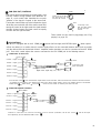
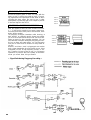
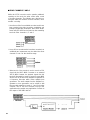
AUX CONTROLS
The MT2X is equipped with an AUX SEND jack
and two (left and right) AUX RETURN jacks
When special
effects are desired on a certain channel, reverb or delay effects can be connected between these jacks to provide
only the desired effect to the desired channel. Amplified monitor speakers can also be connected to the AUX SEND
jack. Each AUX control adjusts the sources connected to the AUX SEND jack in the following manner.
CONNECTING AN EFFECTOR
AUX MASTER
SEND control
AUX controls
Channel 1 signal
Channel 2 signal
Channel 3 signal
Channel 4 signal
Channel 5 signal
Channel 6 signal
Effects device
(digital reverb, digital delay, etc.)
AUX RTN control
To the left & right
stereo mix busses
Raise the AUX control of the channel which requires effects. At the same time, make sure that the AUX controls for the other channels
are adjusted for proper balance. The effected signal, with all the channel signals mixed in, flows in the following manner: AUX MASTER
SEND control effects device AUX RTN . At the end, the sounds are mixed by the stereo mix buss.
CONNECTING MONITOR SPEAKERS
AUX control
AUX MASTER
SEND control
Channel 1 signal
Channel 2 signal
Channel 3 signal
Channel 4 signal
Channel 5 signal
Channel 6 signal
Amplified monitor
speakers
Performers or sound mixers can control the level balance of the four channels (instruments) with the AUX controls
, with the total output
level adjusted by the AUX MASTER SEND control
6

MASTER FADER
This controls the level of all the input faders, as well as the final level of the effected signal of the AUX RTN control
and the sound mixed through the stereo mix buss. The output level of the ST OUT jack (the recording level
at mixdown) and the recording level during ping-ponging are also adjusted with this control.
Set the control input faders at “7” for best results.
AUX MASTER SEND CONTROL
This control adjusts the level of the effect-mixed signals
from each channel (adjusted by each AUX control )
as well as the AUX signal for monitoring use. The final
output is through the AUX SEND jack
AUX RETURN CONTROL
This control adjusts the input level of effects or sub-
mixers connected to the AUX RTN jack . The level of
the effect in relation to the “dry” sound can be set with
this control.
SYNC SWITCH
Normally left in the “OFF” position, this switch should
be set to REC or PB if this unit is to be used for syn-
chronized operation with MIDI products like synthesizers
and rhythm machines. Synchro operation is explained in
the section on Sync-Recording on page 34.
POWER INDICATOR
This indicator lights when the power switch on the
rear panel is turned on.
7

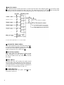
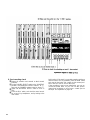
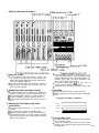
RECORDER SECTION
RECORD SELECT SWITCHES
These switches are used to choose the signal to be
recorded. When the track is not to be recording, set the
corresponding switch to the OFF position. Switch ON
only those switches corresponding to the tracks which
are to record. The panel indications for “L" and “R” cor-
respond to the stereo left and right signals, whereas “1”,
“2”, “3”, and “4” correspond to the signal from the 1,
2, 3, and 4 input channels. Those signals are recorded
on their respective track when the switches are in
position.
NOTE:
Tracks 1 and 3 cannot be recorded from the right
stereo signal, and tracks 2 and 4 cannot be
recorded from the left stereo signal.
REC INDICATORS
Each track on the MT2X has its own REC indicator LED.
When the RECORD SELECT switches are used to set one
or more of the tracks to the REC standby mode (that is,
the selected tracks are ready to record but the cassette
transport is not yet running in the REC mode), the cor-
responding REC INDICATOR(s) will flash. When record-
ing is actually begun, the REC INDICATORS for the
selected tracks will light continuously.
8

9
REC SWITCH
When this switch is pressed, the PLAY switch also
moves, and the unit goes into the recording mode.
However, if the RECORD SELECT switches for all tracks
1-4 are switched OFF, nothing will be recorded.
NOTE: When the REC switch is pressed down, noise
occurs which is recorded on the tape. In order
to prevent this, we recommended the use of the
PAUSE switch . Press the PAUSE switch first,
then press the REC switch. To start recording,
press the PAUSE switch again to shift out of the
REC pause mode
and into the recording mode.
PLAY SWITCH
Press this switch for playback. However, if the input
selector switch of a track is not in the TAPE position,
the sound will not be heard on the stereo buss.
REW SWITCH (REWIND)
Use this switch to rewind the tape. Pressing it when
the MT2X is in the PLAY mode enables you to hear the
sound of the tape while it rewinds. This feature is use-
ful for finding the beginning of a song or other recorded
material.
FF SWITCH (FAST FORWARD)
Use this switch to quickly advance the tape forward.
Pressing it when the MT2X is in the PLAY mode enables
you to hear the sound of the tape while it is moved for-
ward. This feature is useful for cueing up the start of
a subsequent song or other recorded material on the
tape.
STOP SWITCH
Press this to stop tape.
PAUSE SWITCH
Press this switch to momentarily stop playback or
recording in progress. Press it again to restart.
dbx SWITCH
Ordinary cassette tapes don’t have sufficient dynamic
range (the level difference between the softest sounds
and the loudest peaks) to adequately record highly
dynamic music. If the dbx switch is put “ON” during
recording, highly dynamic music signals can be ade-
quately handled, while the hiss noise inherent to cassette
tapes is kept down below the range of human hearing.
If the dbx switch is kept “ON” during recording, it must
also be kept “ON” during playback.
PITCH CONTROL
During recording or playback, this control can be used
to vary the tape running speed from +10% to -10%.
The pitch of voices or musical instruments also varies
in proportion to tape speed.
Under normal conditions, the control should be in the
center position. When overdubbing (playing back a
recorded passage while recording new material on a dif-
ferent track) the pitch of the previously recorded material
can be altered to match the new material if necessary.
This feature can also be used to obtain certain special
effects during recording.
TAPE SPEED SWITCH
This switch selects either LO (4.8 cm/s) or HI (9.5
cm/sec) cassette tape speed. The low-speed setting cor-
responds to standard cassette tape speed, offering max-
imum recording time. The HI setting causes the tape
to run at twice the standard tape speed, reducing avail-
able recording time but significantly improving sound
quality.
TAPE COUNTER
This displays the amount of tape run.
RESET SWITCH
Press this switch to reset the tape counter to “000”.
Pressing this switch at the start of recording, or at the
beginning of a song, makes it easy to cue up the selec-
tion from the start.
ZERO STOP SWITCH
If this switch is set “ON” during rewinding, the tape
will stop when the tape counter reaches “999”. During
multitrack recording, this feature is convenient for
repeated playback or recording operations after rewind.

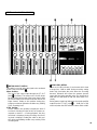
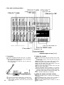
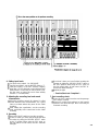
METER AND MONITOR SECTION
METER SELECT SWITCH
This switch is used to select the signal to be monitored
by the Peak Level Meters
Stereo Position:
The level of the signal output through the ST OUT
jacks is indicated. The meter on the far left shows
the level of the Left channel of the stereo signal, while
the second meter from the left shows the level of the
Right channel. Setting to this position during ping-
ponging or mixdown operations enables easy reading
of the recording level.
4 TRK Position:
Set the switch in this position to display the level of
each track. Starting from the far left, each meter cor-
responds to tracks 1–-4. During playback, the play-
back level is displayed; during recording, the record-
ing level is displayed. Setting the switch to this posi-
tion during overdubbing enables easy reading of the
recording level.
PEAK LEVEL METERS
There are 14 LED indicators in each meter which show
a range from - 20dB to +6dB. During recording, setting
levels high (but below the point where the recording
becomes distorted) will ensure the greatest dynamic
range with the lowest possible noise. An ideal point is
when the LED indicators for 0dB and above flash occa-
sionally.
During stereo signal level indication, the actual specified
output from the ST OUT jacks is - 10dB (into a 50K
ohm load) when the LED indicators start to flash at 0dB.
10

PHONES SELECT SWITCH
You can plug a set of headphones into the PHONES jack on the front panel to monitor the sound. The PHONES
SELECT Switch is used to select the signal to be monitored. Control the volume level with the PHONES volume
control .
STEREO Position:
Put the switch in this position to monitor the signal output through the ST OUT jacks .
The Left and Right chan-
nels of the stereo signal will be heard through the headphones.
When set to this position during ping-ponging or mixdown operations, the mixed signal of all the instruments can
be monitored.
MONITOR Position:
This position is for monitoring the signal of each track. You can freely monitor while mixing the sound of each
track during recording or playback. Using the MONITOR LEVEL Controls
set the desired level for each track.
MIX Position:
This position allows you to simultaneously monitor
both the sound heard in the STEREO position and the
sound heard in the MONITOR position. Setting to this
position during punch-in/punch-out operations will
enable the type of monitoring shown below. (Refer to
“Punch-in/Punch-out” on page 27).
For
example,
when adding in instruments or vocals in the following
way:
For retake
11
The sound of
Tracks 1-3
tracks 1-4 plus the
plus the sound
sound of the
of the material
material
to be added.
added.

MONITOR LEVEL CONTROLS
When setting the PHONES SELECT Switch to the
MONITOR position, these level controls are used for each
track to achieve a level balance for easy monitoring. Use
these controls freely and independently to maintain a
desired level balance during overdubbing operations,
when the addition of a new signal changes the volume.
PHONES CONTROL
This control adjusts the volume of the headphones (See
page 10).
CONNECTOR SECTION
FRONT PANEL
INPUT JACKS
The MT2X mixer has six channels and therefore six IN-
PUT jacks. INPUT 1 and 2 can be used with microphones
or line-level sources such as electric and electronic
instruments. INPUT
S 3 through 6 accept only line-level
input.
Plug a set of headphones into this jack for monitoring.
PHONES JACK
Please use headphones rated from 8–40 ohms for best
results.
PUNCH IN/OUT JACK
When directly connecting an electric guitar to one of
the MT2X INPUTs, we recommend the use of a guitar
preamplifier or “direct box” between the guitar and
MT2X to ensure optimum sound quality.
REAR PANEL
By connecting the optional FS-1 footswitch to this jack,
you can control punch-in/punch-out operations by foot.
12

POWER SWITCH
This switch turns on the MT2X. When switching the unit
on or off, make sure that the Input Faders and the
AUX RTN Control are at the “0” position.
SYNC IN/SYNC OUT JACKS
These jacks are used during synchronized operation with
MIDI-equipped instruments. The jacks make it possible
to use an optional YMC10 MIDI Converter in place of the
YMC2 MIDI Converter designed specifically for the
MT2X. For a detailed explanation, refer to “Sync-
Recording” on page 34.
TAPE OUT JACKS
These jacks directly output the signal of each track. Dur-
ing playback, the signals of the tracks being played are
output. During recording, the signals of the tracks be-
ing recorded are output. Since the output level cannot
be adjusted, the input levels of the mixer or recorder
connected to these jacks must be set to match the
output level of the MT2X. These jacks can be conven-
iently used in the following ways:
l Another 4-track recorder can be connected for direct
dubbing of all four channels.
l An external mixer can be connected for mixdown.
ST OUT JACKS
The mixed signals of each channel (and each track) are
output in stereo through these jacks. Since these jacks
output the final mix, a stereo cassette deck can be
connected. These jacks can also be used as follows.
l The MT2X can be used as a sub-mixer, with the out-
put sent to a main mixer through this jack.
l A stereo amplifier or powered monitor speakers can
be connected through this jack.
AUX SEND JACK
This jack outputs the mixed signal from the Aux bus, and
is used as an output terminal for the connection of an
effects device. This can also be used as an additional
monitor output.
AUX RTN JACKS
These jacks are used to input the signal from an effects
device back into the MT2X. As well, the mixed output
from an external mixer can be connected to these jacks.
Please note that if only a single plug is inserted into either
one of these jacks, the signal will be sent to both Left
and Right channels. This is useful if the effects device
being used is mono.
13
YMC2 CONNECTOR
This connector accepts the optional YMC2 MIDI Con-
verter which has been designed for perfect electronic
and cosmetic matching with the MT2X. When installed,
the YMC2 receives its power directly from the MT2X.
The YMC2 is used for tape synchronization of external
MIDI equipment. The synchronization signal is recorded
on track 4 of the MT2X tape.
l
VOLTAGE SELECTOR (General model only)
The MT2X voltage selector is located on the
bottom panel. A standard screwdriver (“minus”
type) can be used to rotate the selector to match
the MT2X to your local AC mains voltage.
* NEVER ADJUST THE VOLTAGE SELECTOR
WHILE THE AC CORD IS PLUGGED IN!
* CHECK THAT THE SELECTED VOLTAGE IS
CORRECT BEFORE PLUGGING IN YOUR MT2X
FOR THE FIRST TIME!

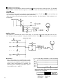
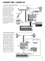
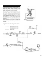
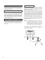
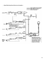
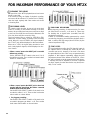
CONNECTION EXAMPLES
n
BASIC MT2X SYSTEM WITH EFFECTS
MT2X + SPX90 + monitor system + mic
+ guitar + DX100 + RX17
This basic recording system puts the
MT2X’s six input channels to good use.
A microphone for vocals and an electric
guitar are plugged into channels 1 and 2,
taking advantage of the low-level input
and level-matching capability provided
by these channels. Channels 3 and 4
receive the stereo outputs from a
Yamaha DX100 Digital Programmable
Algorithm Synthesizer, and the stereo
outputs from a Yamaha RX17 Digital
Rhythm Programmer are plugged into
channels 5 and 6. With a setup like this,
you’re ready to record any source on
virtually any track with no need for
repatching. For top-quality reverb, delay
and other effects a Yamaha SPX90 Multi-
effect Processor is connected into the
MT2X’s AUX SEND/RETURN loop. A sim-
ple but highly effective monitor system
is provided by a pair of Yamaha KS10
powered speakers.
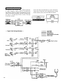
n
MIDI TAPE SYNC SYSTEM
In this system the YMC2 MIDI Converter
converts the MIDI timing signals from the
QX21 Digital Sequence Recorder into
analog signals which are recorded on
track 4 of the tape. On playback, the
analog tape signals are converted back
into MIDI form by the YMC2 and used to
control START and STOP of the QX21.
Thus, playback of the QX21 sequencer,
which controls the DX27 Digital Pro-
grammable Algorithm Synthesizer and
RX17 Digital Rhythm Programmer, is
perfectly synchronized to playback of the
MT2X tape. Other material can now be
recorded on tracks 1 through 3 of the
MT2X
— vocals, acoustic instruments,
etc.
— in perfect synchronization with
the MIDI sequence. The benefit is that
we effectively have more than four
playback tracks, and that the synchronir-
ed MIDI instruments can be modified as
desired: i.e., voices can be changed on
the synthesizer or the QX21 sequence
edited without affecting any other tracks.
AMP
I I
RX17
DX21
MT2X + YMC2 + QX21 + DX27 + RX17 + monitor system
KS10
DX27
14

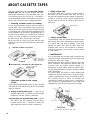
ABOUT CASSETTE TAPES
This unit is designed to be used only with Chrome-
position tape, and will not work properly with Ferri-
chrome tape formulations. CrO
2 tape (Bias: HIGH; EQ:
70µ should be used. Also, the use of C-120 tapes is
not recommended because they exhibit poorer perfor-
mance, and can be the cause of equipment failure.
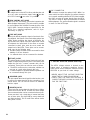
l
Preventing accidental erasure of recordings
To keep from inadvertently erasing a prized recording, all
cassette tapes have record protection tabs along the top
edge of the cassette shell. If this tab is broken out using
a screwdriver or any other appropriate implement, it will
not be possible to record on the corresponding side of
the tape. This will protect your recordings from accidental
erasure. For 4-track recording, it’s necessary to break out
the tabs for both the A and B sides of the tape.
When you’d like to record over a tape with the tabs
broken out, just cover the holes (where the tabs were)
with tape.
PREVENTING ACCIDENTAL TAPE ERASURE:
Break off the tab
with a screwdriver or
similar implement.
RECORDING OVER A TAPE WITH THE TABS BROKEN OUT:
Cover the holewith
l
Playing tapes recorded on other cassette
recorders
When playing Normal-position tapes, or tapes encoded
with Dolby B noise reduction the MT2X, the following
steps are advised:
1) Playing Normal-position tapes — move the HI
equalizer fader in the "+" direction to boost the high
frequencies until the sound is satisfactory.
2) Playing tapes encoded with Dolby B NR — put the
dbx switch in the “OFF” position, and move the HI
equalizer fader in the "-" direction to reduce the
high frequencies until the sound is satisfactory.
l
Taking up tape slack
If the tape is used when it is slack, or some portion of
the tape is out of the cassette shell, there is a risk it
may become tangled around the capstan or pinchroller.
In order to correct this, insert a pencil or ballpoint pen
into the center of one reel, and rotate to take up loose
tape slack.
Cassette shell
l
Storing cassette tapes
To prevent tape slack, fit a stopper into the tape or keep
tapes in their cases. Do not store tapes in direct sunlight,
or in places with high heat or humidity, as this may
damage the tapes. Also, keep the tapes away from
magnetic fields, such as near televisions or speakers,
because the recordings can be erased or sonically altered
to some degree.
l MAINTENANCE
As a good general rule, the tape heads, pinchroller and
capstan should be cleaned before each recording, thus
ensuring the best audio quality.
After the deck has been used for a period of time, the
heads, pinchroller, and capstan will become dirty. This
increases noise and uneven rotation, leading to a
deterioration in sound quality. Therefore, periodic clean-
ing and demagnetization is a must to preserve optimal
audio performance.
Use cotton swabs and alcohol or head cleaning fluid
(available in most all audio stores) to clean the heads,
capstan, and pinchroller. Do not use rubbing alcohol as
this contains mineral oil which can damage the
mechanism. Keeping the heads clean is essential for
good recordings. For demagnetization, use a quality head
demagnetizer, and follow the instructions carefully.
Pinchroller
* It’s important to keep all parts clean!
15

MULTITRACK RECORDING TECHNIQUES
n
ONE EXAMPLE OF A MULTlTRACK
RECORDING PROCESS
Multitrack recording is usually used to record a rhythm
section, with overdubbing and ping-ponging operations
assisting in mixing the parts of the various musicians in
the proper balance. Finally, the tape is mixed down to
produce a stereo master tape.
These are the steps in our example:
Record the drums on track 1
Record the bass on track 2
Record the rhythm guitar on track 3
Ping-ponging tracks 1 –- 3 onto track 4
(freeing tracks 1 – 3)
Record the keyboards on track 3
Record the lead guitar on track 2
Record the vocals on track 1
Mixdown tracks 1 – 4 to produce a stereo
master tape
Track 1
Track 2
Track 3
Track 4
Mixdown
n
BEFORE RECORDING
RECORDING LEVEL
In making a good recording, the most important step is
setting the ideal recording level. If the level is too low,
the recording will contain a lot of noise and hiss; if the
level is too high, the recording will sound distorted and
unclear. The MT2X is equipped with peak level meters
which show the level of each track, as well as the level
of the stereo output signal. Use these meters to help you
set the ideal recording level. If the level meters “peak
out” (show the maximum reading) briefly, it’s not a pro-
blem. However, if they’re peaking out for more than a
second or two, then distortion may become a problem.
dbx SYSTEM
Keep the dbx switch “ON” to expand dynamic range and
to reduce inherent tape noise.
SELECT THE BEST TAPE SPEED
The MT2X gives you a choice of two tape speeds. The
low speed gives you about double the record/playback
time of the high-speed mode — at the expense of
reproduction quality. Use the low-speed mode when
making test recordings or simply trying out ideas. Use
the high-speed mode when you need the best possible
sound quality — when recording an important demo, for
example.
PLAN CAREFULLY FOR MICROPHONE RECORDING
Since the MT2X only permits microphone recording via
channels 1 and 2, one or both of these channels must
be kept available if you plan to record with microphones.
STEREO POSITIONING
It’s important to think about the acoustic “position” of
all the instruments well before you start your multitrack
recording.
Here’s one example of acoustic positioning. Set the bass
drum and the snare drum in the center, with the tom-
toms and high hat set off to either side to bring out the
“stereo” effect. The bass and other “heavy” instruments
should be in the center, with the keyboards to the left
and the guitar to the right. Solo instruments and voices
should span both right and left. Solo instruments with
a stereo output can have their left channel connected
to a delay machine, while the right channel is recorded
directly. You can probably think of many other different
ways to “arrange” the soundstage.
EQUALIZATION AND EFFECT PROCESSING
Equalization and effect processing are usually added at
the ping-pong and mixdown stages. In multitrack record-
ing, these types of signal processing can be decided on
later, and employed to any degree necessary. However,
the MT2X is limited in the number of effects which can
be used during mixdown, so it’s best to use them dur-
ing the initial recording stages.
MONlTORlNG
In addition to circuits for signal recording, this unit also
features a separate monitor circuit to allow the performer
to monitor the levels of the recording in progress through
a pair of headphones. In this case, set the PHONES
SELECT switch to the “MONITOR” position. Adjust the
volume level of each track with its MONITOR LEVEL
controls.
In addition, powered monitor speakers can be directly
connected to the ST OUT jacks or the AUX SEND jack.
16

n
MULTITRACK RECORDING
PLAN YOUR RECORDING
RECORDING THE DRUMS
A clear plan is essential before you begin multitrack
recording. If you begin cold, without regard to all the
steps involved, you may “record yourself into a corner”
by running out of available empty tracks, missing the
chance to add effects at the proper points, losing con-
trol over the final stereo positioning of the instruments,
and creating the need for more ping-pong and mixdown
recording operations than really necessary. Although you
can perform ping-pong and mixdown operations without
limit, a certain amount of noise and sound degradation
results during these operations. It’s best to hold ping-
ponging down to 1 or 2 operations in order to achieve
good sound quality.
So before you start, plan your recording carefully — what
order the parts will be recorded in, what instruments will
go on which tracks, how and when effects will be used,
when recorded tracks will be ping-ponged, and what sort
of end result is desired. The recording process of the ex-
ample we will explain in this section is illustrated on page
16.
The drums will be recorded on track 1. In recent years,
drum machines and rhythm machines have made an
appearance, with Yamaha coming out with the high-
performance RX-series.
In this example we’ll use an RX-series Digital Rhythm pro-
grammer to record a high-quality drum track. The “L” and
“R” stereo outputs from the rhythm programmer are fed
to input channels 1 and 2 of the MT2X, and these are
mixed down onto track 1 of the tape.
The Yamaha SPX90 Multi-effect processor is an ideal
way to add live-sounding reverb to the drums. The
SPX90 is connected between the MT2X AUX SEND and
stereo AUX RTN jacks.
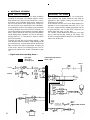
— Signal route when recording drums —
Input signal
Effect signal
Recording signal
Signal displayed by the meter
Monitor signal
Output L
q
Output R
AUX RTN
1717
Effect
OUT 1-1 IN
Meter 1
1
ST OUT

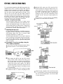
— Drum Recording Procedure —
1. Connections
Plug the AC cord into an AC outlet.
Plug the Digital Rhythm Programmer’s stereo out-
puts into INPUTs 1 and 2.
Plug a pair of monitor headphones (rated 8–40
ohms) into the PHONES jack.
When using an effect, connect it between the AUX
SEND jack (input) and either of the AUX RTN jacks
(output).
2. Getting ready
Lift open the cassette door and insert a chrome
position (CrO2) tape.
Bias: HIGH, Eq: 70µs.
Return all the switches and controls to their nor-
mal positions, referring to the control panel illustra-
tion on pages 4~10.
Turn the power switches on for the effect and
rhythm programmer, and then turn the MT2X "ON".
The POWER indicator will light.
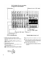
3. Setting up the recorder section
Press the RESET switch to return the counter to
"000".
Turn "ON" the ZERO STOP switch.
Turn "ON" the dbx switch.
Select the appropriate tape speed the 9.5 cm/sec.
is recommended.
Set the RECORD SELECT switch 1 to the "L" posi-
tion. This is to record the Left stereo signal onto
track 1. The REC indicator will begin flashing.
Press the pause switch to start the recording. The
REC indicator will light up completely.
18
La pagina si sta caricando...
La pagina si sta caricando...
La pagina si sta caricando...
La pagina si sta caricando...
La pagina si sta caricando...
La pagina si sta caricando...
La pagina si sta caricando...
La pagina si sta caricando...
La pagina si sta caricando...
La pagina si sta caricando...
La pagina si sta caricando...
La pagina si sta caricando...
La pagina si sta caricando...
La pagina si sta caricando...
La pagina si sta caricando...
La pagina si sta caricando...
La pagina si sta caricando...
La pagina si sta caricando...
La pagina si sta caricando...
La pagina si sta caricando...
La pagina si sta caricando...
La pagina si sta caricando...
-
 1
1
-
 2
2
-
 3
3
-
 4
4
-
 5
5
-
 6
6
-
 7
7
-
 8
8
-
 9
9
-
 10
10
-
 11
11
-
 12
12
-
 13
13
-
 14
14
-
 15
15
-
 16
16
-
 17
17
-
 18
18
-
 19
19
-
 20
20
-
 21
21
-
 22
22
-
 23
23
-
 24
24
-
 25
25
-
 26
26
-
 27
27
-
 28
28
-
 29
29
-
 30
30
-
 31
31
-
 32
32
-
 33
33
-
 34
34
-
 35
35
-
 36
36
-
 37
37
-
 38
38
-
 39
39
-
 40
40
-
 41
41
-
 42
42


Yamaha MT2X Manuale del proprietario
- Categoria
- Microfoni
- Tipo
- Manuale del proprietario
- Questo manuale è adatto anche per
in altre lingue
- English: Yamaha MT2X Owner's manual
- français: Yamaha MT2X Le manuel du propriétaire
- español: Yamaha MT2X El manual del propietario
- Deutsch: Yamaha MT2X Bedienungsanleitung
- русский: Yamaha MT2X Инструкция по применению
- Nederlands: Yamaha MT2X de handleiding
- português: Yamaha MT2X Manual do proprietário
- dansk: Yamaha MT2X Brugervejledning
- čeština: Yamaha MT2X Návod k obsluze
- polski: Yamaha MT2X Instrukcja obsługi
- svenska: Yamaha MT2X Bruksanvisning
- Türkçe: Yamaha MT2X El kitabı
- română: Yamaha MT2X Manualul proprietarului
Documenti correlati
-
Yamaha MT120S Manuale utente
-
-
-
-
-
-
-
-
-