Electrolux EFC639.1X/CH Manuale utente
- Categoria
- Cappe da cucina
- Tipo
- Manuale utente
Questo manuale è adatto anche per

Gebrauchsanweisung , Manuel d'utilisation
EFC 939.1
EFC 639.1
F ID
Istruzioni per l'uso , User manual
UK

29
Contents
Safety warnings 30
For kitchen unit installer 30
For user 30
Description of the appliance 31
Mounting of grease filters 31
Function 31
Extractor version 31
Filter version 31
Using the hood 32
Control devices for the grease filter and carbon filter 32
Grease filter saturation led 32
Carbon filter saturation led 32
To restore the LED for the filter warnings. 32
Correct ventilation 32
Maintenance 33
Cleaning 33
Metal grease filter 33
Open the metal grease filter 33
Warning 33
Carbon filter 34
Changing the light bulb 34
Technic Details 35
Special accessories 35
Installation 35
Unpacking 35
Placement 35
Electrical connection 35
Wall unit mounting 36
Mounting of hood 36
UK
Before you use the cooker hood we recommend that you read through the whole user manual giving a
direct description of the cooker hood and its functions.
To avoid the risks, that are always present when you use a product driven by electricity, it is important
that the cooker hood is installed correctly and that you read the safety instructions carefully to avoid
misuse and hazard.
Save the instruction manual and keep it available at use of the cooker hood

30
Safety warnings
For kitchen unit installer
Attention: The air outlet must not be connected
to chimney flues or combustion gas ducts. The
air outlet must under no circumstances be
connected to ventilation ducts for rooms in
which fuel-burning appliances are installed.
• When used as an extractor unit, the hood
must be fitted with a 150mm diameter hose.
• When installing the hood, make sure you
respect the following minimum distance
from the top edge of the cooking hob/ring
surfaces:
electric cookers 600 mm
gas cookers 750 mm
coal and oil cookers 850 mm min.
• If the cooker hood is operating in the suction
version concurrently to other combustion
appliances you will need to ensure that the
depression in the environment of these instal-
lations does not exceed the 4PA (4x10
-5
bar).
• The air outlet must not be connected to
chimney flues or combustion gas ducts. The
air outlet must under no circumstances be
connected to ventilation ducts for rooms in
which fuel-burning appliances are installed.
• It is advisable to apply for authorization from
the relevant controlling authority when
connecting the outlet to an unused chimney
flue or combustion gas duct.
The air outlet installation must comply with
the regulations laid down by the relevant
authorities.
• When the unit is used in its extractor version,
a sufficiently large ventilation hole must be
provided, with dimensions that are approxi-
mately the same as the outlet hole.
• National and regional building regulations
impose a number of restrictions on using
hoods and fuel-burning appliances connected
to a chimney, such as coal or oil room-
heaters and gas fires, in the same room.
• Since the rule for rooms with fuel burning
appliances is “outlet hole of the same size as
the ventilation hole”, a hole of 500-600 cm
2
,
which is to say a larger hole, could reduce
the performance of the extractor hood.
• If the hood is used in its filtering function, it
will operate simply and safely in the above
conditions without the need for any of the
aforementioned measures.
• When the hood is used in its extractor func-
tion, the following rules must be followed to
obtain optimal operation:
— short and straight outlet hose
— keep bends in outlet hose to a minimum
— never install the hoses with an acute
angle, they must always follow a gentle
curve only
— keep the hose as large as possible (prefer-
ably the same diameter as the outlet hole).
• Failure to observe these basic rules will
drastically reduce the performance and
increase the noise levels of the extractor
hood.
For user
• Always cover lighted elements, to prevent
excess heat from damaging the appliance. In
the case of oil, gas and coal fired cookers it is
essential to avoid open flames.
• Also, when frying, keep the deep frying pan
on the cooker top/cooker under careful
control.
• The hot oil in the frying pan might ignite due
to overheating.
• The risk of self-ignition increases when the
oil being used is dirty.
• It is extremely important to note that over-
heating can cause a fire.
• Never carry out any flambé cooking under
the hood.
• Always disconnect the unit from the power
supply before carrying out any work on the
hood, including replacing the light bulb
(take the cartridge fuse out of the fuse holder
or switch off the automatic circuit breaker).
• It is very important to clean the hood and
replace the filter at the recommended
intervals. Failure to do so could cause
grease deposits to build up, causing a fire
hazard.

31
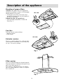
Mounting of grease filters
Attention! The grease filters are supplied not
mounted and packed in order to avoid damages
during transport of the hood.
• Fit the pins of the filter on the slots of the
grease filter housing, then use the handles of
the filter to lock them.
Dismount the filter the opposite way.
• Pull the handles backwards to loosen the
filter (Fig. 1).
Function
The hood may be used as follows:
- Extractor version
- Filter version
Extractor version
The air is vented outdoors by a 150 mm duct
which must be connected to connecting ring
on top of the motor package.
Filter version
The air is filtered through an activated charcoal
filter and returned to the kitchen through the top
grill of the outlet pipe (fig. 2).
This version is used when there is no exhaust
duct for venting outdoors or when it is impossi-
ble to install one.
Description of the appliance
a
b
a
b
Fig. 2
Fig. 1
EFC 639
EFC 939

32
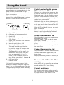
Using the hood
The hood has one variable speed motor. For the
best performance, we recommend using the low
speeds in normal conditions and the high
speeds in particular cases of strong odour and
vapour concentration.
We recommend starting up the hood a few
minutes before cooking and keeping it running
until all the odours have been eliminated.
A – Motor OFF button
B – ON button and motor speed selection
button 1 - 2 - 3 - 1 - 2 - . . . .
E – Speed 1 LED
F – Speed 2 LED and grease filter saturation
LED (flashes)
C – Speed 3 LED and carbon filter saturation
LED (flashes)
D – Intensive speed indicator LED
G – Intensive speed ON switch
This speed should be used when the
concentration of cooking fumes or odours
is particularly strong (for example when
frying, cooking fish etc.).
The fast speed will run for about 5 min-
utes and then return to the speed previ-
ously set automatically (1, 2 or 3), or
switch off if no speed was selected. To
turn off the fast speed, before the end of
the 5 minutes, press button A or button B.
H – OFF lamp button
I – ON lamp button
If the hood fails to operate correctly, briefly
disconnect it from the mains power supply for
almost 5 sec. by pulling out the plug. Then plug
it in again and try once more before contacting
the Technical Assistance Service.
Control devices for the grease
filter and carbon filter
This hood has a device which warns you when
to clean the grease filter or replace the carbon
filter (in the case of the air recircultion version).
This hood is delivered without a carbon filter.
For this reason the warning signal to replace the
carbon filter is not connected.
If the hood will be used for recirculation of air,
with carbon filter, the warning signal have to be
connected as follows: Press the buttons B and G
at the same time for about 3 seconds. The LED
marked F lights up.
When the LED marked C lights up, the warning
signal is connected.
To disconnect the warning signal, press the
buttons B and G at the same time for about 3
seconds until the LED marked C goes out.
Grease filter saturation led
The LED marked F warns you when the grease
filter needs to be cleaned.
This LED flashes to warn you that the grease
filters must be cleaned.
Generally, these must be cleaned after 40 hours
of use.
Read the maintenance instructions provided for
the grease filters.
Carbon filter saturation led
The LED marked C indicates carbon filter needs
to be replaced.
This must be done after approximately 160
hours of use.
Read the instructions provided for replacing the
carbon filter.
To restore the LED for the filter
warnings.
After cleaning of the grease filter and exchange
of the carbon filter, press button A for about 3
seconds until the LED F stops flashing.
Correct ventilation
To have the cooker hood working correctly
the windows in the kitchen should be closed.
In stead a window in an adjacent room
should be open.
0 123
5 MIN
0I
FC
BEFCD
G
A
H
I

33
The hood must always be disconnected
from the mains power supply before
beginning any maintenance work.
Cleaning
• Warning: always disconnect the hood from
the mains power supply before cleaning it.
Never insert pointed objects in the motor’s
protective grid.
• Wash the outside surfaces using a delicate
detergent solution. Never use caustic deter-
gents or abrasive brushes or powders.
• Only ever clean the switch panel and filter
grille using a damp cloth and delicate deter-
gents.
• It is extremely important to clean the unit and
change the filters at the recommended inter-
vals. Failure to do so will cause grease depos-
its to build up that could constitute a fire
hazard.
Metal grease filter
• The purpose of the grease filters is to aspirate
grease particles which form during cooking
and it must always be used, either in the
external evacuation or internal recycling
function.
Attention: the metal grease filters must be
removed and washed, either by hand or in
the dishwasher, every four weeks.
Open the metal grease filter
• Pull the handles backwards to loosen the
filter. Fig. 3.
Hand washing
Soak grease filters for about one hour in hot
water with a grease-loosening cleaner, then
rinse off thoroughly with hot water. Repeat
the process if necessary. Refit the grease
filters when it are dry.
Dishwasher machine
Place grease filters in dish washer. Select
most powerful washing programme and
highest temperature, at least 65°C. Repeat the
process. Refit the grease filters when it are
dry.
When washing the metal grease filter in the
dishwasher a slight discoloration of the filter
can occur, this does not have any impact on
its performance.
• Clean the inner housing using a hot deter-
gent solution only (never use caustic deter-
gents, abrasive powders or brushes).
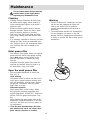
Maintenance
Warning
• Failure to observe the instructions on clean-
ing the unit and changing the filters will
cause a fire hazard. You are therefore
strongly recommended to follow these in-
structions.
• The manufacturer declines all responsibility
for any damage to the motor or any fire
damage linked to inappropriate maintenance
or failure to observe the above safety recom-
mendations.
Fig. 3

34
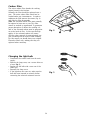
Changing the light bulb
• Disconnect the cooker hood from the main
supply.
• Remove the lamp cover, use a screw driver as
a lever. Fig. 5.
• Replace the old bulb with a new one of the
same type.
• Remount the lamp cover.
• If the light does not come on, make sure the
bulb has been inserted in correctly before
contacting the technical assistance service.
Fig. 4
Fig. 5
Carbon filter
The active carbon filter absorbs the cooking
vapors formed in the kitchen.
Normally the filter should be replaced once a
year. The active carbon filter should not be
washed under any circumstances. In order to
substitute the filter remove the screws (fig. 4)
and slide the filter downwards.
Note: the activated carbon filter must normally
be replaced at least once a year. This filter
cannot be washed or regenerated. To guarantee
proper absorption of odours the working vol-
ume of the activated carbon must be proportion-
ate to the hood air flow. In this case the high
quality of the activated carbon will ensure
efficient odour removal for approximately one
year, assuming that the hood is used normally.
For this reason you should always use original
Electrolux filters only, making sure they are
replaced when necessary.

35
Installation
Unpacking
Check that the cooker hood has no damages.
Transportation damages should immediately be
reported to the one responsible for the transport
Damages, faults and eventually missing details
should immediately be reported to the seller.
Take care of the packing material so that small
children cannot play with it.
Placement
The hood is to be mounted on the wall.
When installed, the hood must be not less than
60 cm. above electric burners or 75 cm. above
gas or mixed-fuel burners (fig. 6).
Electrical connection
The hood has a power cord with moulded plug
with earth connection to be connected to a wall
outlet of 230 V.
The power outlet should be pre-mounted in
such a way that the power cord is invisible
when the hood is fully mounted.
The power cord length is 1,25 m.
Safety warnings for the electrician
Before connecting the appliance to the power
supply, check that the voltage indicated on the
rating plate corresponds to the mains power
supply available. Appliances fitted with a plug
can be connected to any standard power socket
within easy access.
Should it be necessary to provide a fixed con-
nection, the hood must only be installed by an
electrician authorised by the local electricity
board. When installing, an omnipolar
Min
75 cm
Min
60 cm
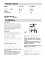
Technic Details
Model EFC 939.1 EFC 639.1
Dimensions height 590 - 910 mm 590 - 910 mm
width 898 mm 598 mm
depth 490 mm 490 mm
Lighting 2 x 20 W 2 x 20 W
Grease filter 2 1
max absorbed power 200 W 200 W
We reserve the right to generate constructive and chromatic modifications as required by technological
growth.
Special accessories
Carbon filter 942 120 182
disconnector with a distance of at least 3 mm
between contacts must be provided.
This disconnector may be for example a switch,
fuses (plug fuses must be removed from the
fuse box, fault current switches and remote
switches with a distance of over 3 mm between
contacts.
The manufacture declines all responsibility for
malfunctions resulting from failure to comply
with the above instructions.
If the power socket is applied directly above the
hood this gives two advantages:
1. the socket is not visible.
2. the appliance can be disconnected at need
merely be removing the plug.
Electrical connection
220-240 V – by means of fixed power cable
with plug.
(Fixed connection of the appliance must only be
carried out by an authorised electrician.)
Fig. 6

36
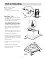
Wall unit mounting
Mounting of hood
• Fit the drilling scheme onto the wall at the
right height. (Fig. 7).
The lower edge of the scheme correspond to
the lower edge of the cooker hood.
• On the drilling scheme is printed a line
corresponding to the centre of the appliance;
with a pencil draw a line up to the ceiling,
this will aid installation procedures. (Fig. 7).
• Drill as indicated on the scheme and fit two
dowels, two hooks and two screws 5x45.
(Fig. 7).
• Hang the hood, adjust the position using the
screws on the hooks of the hood. (Fig. 8).
• Release the grease filters. (Fig. 3).
• From the inside of the hood mark on the wall
the point corresponding to the hole which
will be used to fix definitively the hood. (Fig.
9).
• Remove the hood.
• Drill two hole (Ø 8mm) and fit two dowels.
(Fig. 9).
• Hang the hood again on the hooks.
• From inside of the hood insert the definitive
fixing screws. (Fig. 9).
Fig. 7
Fig. 8
Fig. 9
Standard accessories included:
• Screws for mounting
• Drilling scheme
• No return valve (mounted on air outlet)

37
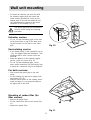
Wall unit mounting
• To mount the chimney you must first affix
the chimney support with the screws and
screw anchors provided (Ø 8 mm) on the
highest point of the wall that meets the ceil-
ing, perpendicular in respect to the lowest
connector of the chimney (fig. 10).
The power plug must be disconnected
from the mains during the mounting
procedure.
Extractor version
• Fit a Ø 150 mm exhausting pipe or flex tube
on the hood outlet on top of the motor hous-
ing and connect it to the wall or roof outlet
pipe.
Recirculating version
• If not already fitted, fit the connection ring (a
- Fig. 10) supplied (bajonett attachment - turn
clockwise and fix with a screw) on the de-
flector b.
• Insert the deflector in the chimney support
and fix it with two screws (Fig. 10).
• Fit a Ø 150 mm exhausting pipe on the
motor outlet connection ring sufficiently long
to reach the connection ring on the deflector.
For both versions:
• Now connect the power plug to the wall
outlet.
• Fix the chimney top part on its support with
two screws (Fig. 10).
• Slide the lower section of the chimney down-
wards and insert it on its proper housing on
the upper side of the hood.
Mounting of carbon filter (for
filter version)
• Remove the grease filter.
• Fix the carbon filter with its two screws (Fig.
11).
• Replace the grease filter.
b
a
Fig. 10
Fig. 11


Kundendienst
Service après-vente
Servizio post-vendita
Servicestellen Points de service Servizio dopo vendita
Zürich/Mägenwil
5506 Mägenwil
Industriestr. 10
1028 Préverenges
Le Trési 6
6916 Grancia
Zona Industriale E
9000 St. Gallen
Vonwilstrasse 15
1950 Sion
Rue de la Piscine
4133 Pratteln
Rheinpark-Center
Netzibodenstr. 23b
8604 Volketswil
Hözliwiesenstrasse 12
6032 Emmen
Buholzstrasse 1
7000 Chur
Comercialstrasse 19
3063 Ittingen/Bern
Ey 5
Ersatzteilverkauf Point de vente de
rechange
Vendita pezzi di
ricambio
5506 Mägenwil
Industriestrasse 10
Tel. 0848 848 023
5506 Mägenwil
Industriestrasse 10
Tel. 0848 848 023
5506 Mägenwil
Industriestrasse 10
Tel. 0848 848 023
Kochberatung /
Verkauf
Demonstration /
Vente
Consulente (cucina) /
Vendita
8048 Zürich
Badenerstrasse 587
Tel. 01 405 81 11
8048 Zürich
Badenerstrasse 587
Tel. 01 405 81 11
8048 Zürich
Badenerstrasse 587
Tel. 01 405 81 11
Garantie Garantie Garanzia
Wir gewähren auf allen
Produkten, die in der Schweiz
gekauft und in Betrieb sind, eine
einjährige Vollgarantie, gerechnet
ab Lieferdatum an den Endver-
braucher. Massgebend für den
Garantieanspruch ist die Faktura
oder ein entsprechen-der
Verkaufsbeleg
L'utilisateur final de tout produit
acheté et utilisé en Suisse,
bénéficie d'une garantie complète
d'une année à partir de la date de
livraison. La facture ou le
justificatif d'achat correspondant
fait foi en la matière.
Per questo prodotto concediamo
una garanzia di 12 mesi a partire
della data di vendita. La garanzia
è valida dietro presentazione
della fattura o dello scontrino
d'acquisto.
LI1VWB Ed. 01/02
-
 1
1
-
 2
2
-
 3
3
-
 4
4
-
 5
5
-
 6
6
-
 7
7
-
 8
8
-
 9
9
-
 10
10
-
 11
11
-
 12
12
-
 13
13


Electrolux EFC639.1X/CH Manuale utente
- Categoria
- Cappe da cucina
- Tipo
- Manuale utente
- Questo manuale è adatto anche per
in altre lingue
- English: Electrolux EFC639.1X/CH User manual