Yamaha RX-777 Manuale utente
- Categoria
- Sintonizzatori audio
- Tipo
- Manuale utente

UCA
RX-777
YAMAHA ELECTRONICS CORPORATION, USA 6660 ORANGETHORPE AVE., BUENA PARK, CALIF. 90620, U.S.A.
YAMAHA CANADA MUSIC LTD. 135 MILNER AVE., SCARBOROUGH, ONTARIO M1S 3R1, CANADA
YAMAHA ELECTRONIK EUROPA G.m.b.H. SIEMENSSTR. 22-34, 25462 RELLINGEN BEI HAMBURG, F.R. OF GERMANY
YAMAHA ELECTRONIQUE FRANCE S.A. RUE AMBROISE CROIZAT BP70 CROISSY-BEAUBOURG 77312 MARNE-LA-VALLEE CEDEX02, FRANCE
YAMAHA ELECTRONICS (UK) LTD. YAMAHA HOUSE, 200 RICKMANSWORTH ROAD WATFORD, HERTS WD1 7JS, ENGLAND
YAMAHA SCANDINAVIA A.B. J A WETTERGRENS GATA 1, BOX 30053, 400 43 VÄSTRA FRÖLUNDA, SWEDEN
YAMAHA MUSIC AUSTRALIA PTY, LTD. 17-33 MARKET ST., SOUTH MELBOURNE, 3205 VIC., AUSTRALIA
Printed in Malaysia V716970
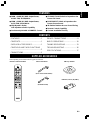
OWNER’S MANUAL
MODE D’EMPLOI
Stereo Receiver
Thank you for selecting this YAMAHA stereo receiver.
Nous vous remercions d’avoir porté votre choix sur ce récepteur stéréo YAMAHA.
Récepteur Stéréo

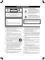
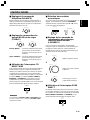
SAFETY INSTRUCTIONS
CAUTION
RISK OF ELECTRIC SHOCK
DO␣ NOT OPEN
CAUTION: TO REDUCE THE RISK OF
ELECTRIC SHOCK, DO NOT REMOVE
COVER (OR BACK). NO USER-SERVICEABLE
PARTS INSIDE. REFER SERVICING TO QUALIFIED
SERVICE PERSONNEL.
The lightning flash with arrowhead
symbol, within an equilateral triangle, is
intended to alert you to the presence of
uninsulated “dangerous voltage” within the
product’s enclosure that may be of
sufficient magnitude to constitute a risk of
electric shock to persons.
The exclamation point within an
equilateral triangle is intended to alert you
to the presence of important operating and
maintenance (servicing) instructions in the
literature accompanying the appliance.
• Explanation of Graphical Symbols
IMPORTANT!
Please record the serial number of this unit in the space
below.
Model:
Serial No.:
The serial number is located on the rear of the unit.
Retain this Owner’s Manual in a safe place for future
reference.
WARNING
TO REDUCE THE RISK OF FIRE OR ELECTRIC
SHOCK, DO NOT EXPOSE THIS UNIT TO RAIN OR
MOISTURE.
1 Read Instructions – All the safety and operating instructions
should be read before the unit is operated.
2 Retain Instructions – The safety and operating instructions
should be retained for future reference.
3 Heed Warnings – All warnings on the unit and in the
operating instructions should be adhered to.
4 Follow Instructions – All operating and other instructions
should be followed.
5 Water and Moisture – The unit should not be used near
water – for example, near a bathtub, washbowl, kitchen
sink, laundry tub, in a wet basement, or near a swimming
pool, etc.
6 Carts and Stands – The unit should be used only with a cart
or stand that is recommended by the manufacturer.
6A A unit and cart combination should be moved
with care. Quick stops, excessive force, and
uneven surfaces may cause the unit and cart
combination to overturn.
7 Wall or Ceiling Mounting – The unit should be mounted to
a wall or ceiling only as recommended by the manufacturer.
8 Ventilation – The unit should be situated so that its location
or position does not interfere with its proper ventilation.
For example, the unit should not be situated on a bed, sofa,
rug, or similar surface, that may block the ventilation
openings; or placed in a built-in installation, such as a
bookcase or cabinet that may impede the flow of air
through the ventilation openings.
9 Heat – The unit should be situated away from heat sources
such as radiators, stoves, or other appliances that produce
heat.
10 Power Sources – The unit should be connected to a power
supply only of the type described in the operating
instructions or as marked on the unit.
11 Power-Cord Protection – Power-supply cords should be
routed so that they are not likely to be walked on or pinched
by items placed upon or against them, paying particular
attention to cords at plugs, convenience receptacles, and the
point where they exit from the unit.
12 Cleaning – The unit should be cleaned only as
recommended by the manufacturer.
13 Lightning – For added protection for this product during a
lightning storm, or when it is left unattended and unused
for long periods of time. Unplug it from the wall outlet and
disconnect the antenna or cable system. This will prevent
damage to the product due to lightning and power-line
surges.
14 Object and Liquid Entry – Care should be taken so that
objects do not fall into and liquids are not spilled into the
inside of the unit.
15 Damage Requiring Service – The unit should be serviced
by qualified service personnel when:
A. The power-supply cord or the plug has been damaged;
or
B. Objects have fallen, or liquid has been spilled into the
unit; or
C. The unit has been exposed to rain; or
D. The unit does not appear to operate normally or exhibits
a marked change in performance; or
E. The unit has been dropped, or the cabinet damaged.
16 Servicing – The user should not attempt to service the unit
beyond those means described in the operating instructions.
All other servicing should be referred to qualified service
personnel.
17 Power Lines – An outdoor antenna should be located away
from power lines.
18 Grounding or Polarization – Precautions should be taken so
that the grounding or polarization is not defeated.

English
We Want You Listening For A Lifetime
YAMAHA and the Electronic Industries Association’s Consumer Electronics Group want you to get the most
out of your equipment by playing it at a safe level. One that lets the sound come through loud and clear
without annoying blaring or distortion – and, most importantly, without affecting your sensitive hearing. Since
hearing damage from loud sounds is often undetectable until it is too late, YAMAHA and the Electronic
Industries Association’s Consumer Electronics Group recommend you to avoid prolonged exposure from
excessive volume levels.
FCC INFORMATION (for US customers only)
1. IMPORTANT NOTICE: DO NOT MODIFY THIS
UNIT!
This product, when installed as indicated in the
instructions contained in this manual, meets FCC
requirements. Modifications not expressly approved by
Yamaha may void your authority, granted by the FCC,
to use the product.
2. IMPORTANT: When connecting this product to
accessories and/or another product use only high
quality shielded cables. Cable/s supplied with this
product MUST be used. Follow all installation
instructions. Failure to follow instructions could void
your FCC authorization to use this product in the USA.
3. NOTE: This product has been tested and found to
comply with the requirements listed in FCC
Regulations, Part 15 for Class “B” digital devices.
Compliance with these requirements provides a
reasonable level of assurance that your use of this
product in a residential environment will not result in
harmful interference with other electronic devices.
This equipment generates/uses radio frequencies and, if
not installed and used according to the instructions found
in the users manual, may cause interference harmful to
the operation of other electronic devices.
Compliance with FCC regulations does not guarantee
that interference will not occur in all installations. If this
product is found to be the source of interference, which
can be determined by turning the unit “OFF” and “ON”,
please try to eliminate the problem by using one of the
following measures:
Relocate either this product or the device that is being
affected by the interference.
Utilize power outlets that are on different branch (circuit
breaker or fuse) circuits or install AC line filter/s.
In the case of radio or TV interference, relocate/reorient
the antenna. If the antenna lead-in is 300 ohm ribbon
lead, change the lead-in to coaxial type cable.
If these corrective measures do not produce satisfactory
results, please contact the local retailer authorized to
distribute this type of product. If you can not locate the
appropriate retailer, please contact Yamaha Electronics
Corp., U.S.A. 6660 Orangethorpe Ave, Buena Park, CA
90620.
The above statements apply ONLY to those products
distributed by Yamaha Corporation of America or its
subsidiaries.
Note to CATV system installer:
This reminder is provided to call the CATV system
installer’s attention to Article 820-40 of the NEC that
provides guidelines for proper grounding and, in
particular, specifies that the cable ground shall be
connected to the grounding system of the building, as
close to the point of cable entry as practical.
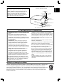
EXAMPLE OF ANTENNA GROUNDING
MAST
GROUND
CLAMP
ANTENNA
LEAD IN
WIRE
ANTENNA
DISCHARGE UNIT
(NEC SECTION 810–20)
GROUNDING CONDUCTORS
(NEC SECTION 810–21)
GROUND CLAMPS
POWER SERVICE GROUNDING
ELECTRODE SYSTEM
(NEC ART 250. PART H)
ELECTRIC
SERVICE
EQUIPMENT
NEC
– NATIONAL ELECTRICAL CODE
SAFETY INSTRUCTIONS

CAUTION
CAUTION: READ THIS BEFORE OPERATING YOUR UNIT.
1 To assure the finest performance, please read this
manual carefully. Keep it in a safe place for future
reference.
2 Install this unit in a well ventilated, cool, dry, clean
place with at least 30 cm on the top, 20 cm on the right
and left, and 10 cm at the back of this unit — away from
direct sunlight, heat sources, vibration, dust, moisture,
and/or cold.
3 Locate this unit away from other electrical appliances,
motors, or transformers to avoid humming sounds. To
prevent fire or electrical shock, do not place this unit
where it may get exposed to rain, water, and/or any type
of liquid.
4 Do not expose this unit to sudden temperature changes
from cold to hot, and do not locate this unit in a
environment with high humidity (i.e. a room with a
humidifier) to prevent condensation inside this unit,
which may cause an electrical shock, fire, damage to
this unit, and/or personal injury.
5 On the top of this unit, do not place:
– Other components, as they may cause damage and/or
discoloration on the surface of this unit.
– Burning objects (i.e. candles), as they may cause fire,
damage to this unit, and/or personal injury.
– Containers with liquid in them, as they may cause
electrical shock to the user and/or damage to this
unit.
6 Do not cover this unit with a newspaper, tablecloth,
curtain, etc. in order not to obstruct heat radiation. If the
temperature inside this unit rises, it may cause fire,
damage to this unit, and/or personal injury.
7 Do not plug in this unit to a wall outlet until all
connections are complete.
8 Do not operate this unit upside-down. It may overheat,
possibly causing damage.
9 Do not use force on switches, knobs and/or cords.
10 When disconnecting the power cord from the wall
outlet, grasp the plug; do not pull the cord.
11 Do not clean this unit with chemical solvents; this might
damage the finish. Use a clean, dry cloth.
12 Only voltage specified on this unit must be used. Using
this unit with a higher voltage than specified is
dangerous and may cause fire, damage to this unit, and/
or personal injury. YAMAHA will not be held
responsible for any damage resulting from use of this
unit with a voltage other than specified.
13 To prevent damage by lightning, disconnect the power
cord from the wall outlet during an electrical storm.
14 Take care of this unit so that no foreign objects and/or
liquid drops inside this unit.
15 Do not attempt to modify or fix this unit. Contact
qualified YAMAHA service personnel when any service
is needed. The cabinet should never be opened for any
reasons.
16 When not planning to use this unit for long periods of
time (i.e. vacation), disconnect the AC power plug from
the wall outlet.
17 Before moving this unit, press STANDBY/ON to set
this unit in the standby mode, and disconnect the AC
power plug from the wall outlet.
18 Be sure to read the “TROUBLESHOOTING” section on
common operating errors before concluding that this
unit is faulty.
This unit is not disconnected from the AC power source
as long as it is connected to the wall outlet, even if this
unit itself is turned off. This state is called the standby
mode. In this state, this unit is designed to consume a
very small quantity of power.
FOR CANADIAN CUSTOMERS
To prevent electric shock, match wide blade of plug to
wide slot and fully insert.
This Class B digital apparatus complies with Canadian
ICES-003.

E-1
APPENDIX
English
● 100W + 100W (8Ω) RMS Output Power,
0.019% THD, 20–20,000 Hz
● 120W + 120W (6Ω) RMS Output Power,
0.03% THD, 20–20,000 Hz
● High Dynamic Power,
Low Impedance Drive Capability
● Continuously Variable LOUDNESS Control
FEATURES
● CD DIRECT AMP Switch to Reproduce the
Purest CD Sound
● PURE DIRECT Switch to Reproduce the
Purest Source Sound
● 40-Station Random Access Preset Tuning
● Remote Control Capability
● Custom Installation Facility
SUPPLIED ACCESSORIES
After unpacking, check that the following parts are included.
VOLUME
SPEAKER
TUNER
TAPE
CD
SLEEP
D–TV VCR
CDTUNER
PRESET
PHONO
DIR BDIR A
POWER
DISC SKIP
A/B/C/D/E
DECK
A/B
TAPE
DVD
BA
+
+
MD
/
Remote Control Transmitter Indoor FM Antenna
AM Loop Antenna
(Australia model)
Batteries (size AA, R6, UM-3)
CONTENTS
FEATURES ............................................1
CONTENTS............................................1
SUPPLIED ACCESSORIES...................1
CONTROLS AND THEIR FUNCTIONS
...............................................................2
CONNECTIONS.....................................5
ZONE 2 CONNECTIONS.......................8
BASIC OPERATIONS ..........................10
TUNING OPERATIONS .......................13
TROUBLESHOOTING .........................16
SPECIFICATIONS................................17
(U.S.A. and Canada models)

E-2
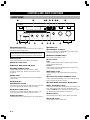
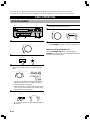
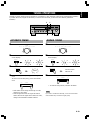
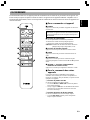
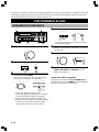
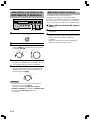
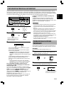
CONTROLS AND THEIR FUNCTIONS
FRONT PANEL
NATURAL SOUND
BASS
PHONES
AB
STANDBY/ON
SPEAKERS
A/B/C/D/E 1 2 4 5 6 7 83
TREBLE BALANCE LOUDNESS
FLAT
TAPE/MD
DVD
D-TV
VCR
CD
TUNER
VCR · D-TV · DVD · TAPE/MD · TUNER · CD · PHONO
PHONO
AUTO/MAN'L MONO
1
2
4
5
3
6
7
8
9
0
2
4
8
12
16
20
28
40
60
–dB
10
0
11
2
4
5LR
3
5
4
3
2
0
11
2
4
5
3
5
4
3
2
0
11
2
4
5
———
—
—
—
3
5
4
3
2
-30%
TUNING MODE
REC OUT/ZONE 2
EDIT FM/AM
TUNING
DOWN UP
MEMORY
MAN'L/AUTO FM
INPUT
PURE
DIRECT
CD DIRECT
AMP
VOLUME
∞
STEREO
RECEIVER
RX–777
123456789
0q w e r t yui o p
1 STANDBY/ON switch
Press this switch to turn on the power to this unit. Press it again to
turn this unit into the standby mode.
Standby mode
In this state, this unit consumes a very small quantity of power
to receive infrared-signals from the remote control transmitter.
2 Display panel
Shows various information. (For details, refer to page 4.)
3 Remote control sensor
4 MEMORY (MAN’L/AUTO FM) button
5 TUNING DOWN/UP button
Used for tuning. Press the “UP” side to tune in to higher
frequencies, and press the “DOWN” side to tune in to lower
frequencies.
6 EDIT button
This button is used to exchange the places of two preset stations
with each other.
7 FM/AM button
8 PURE DIRECT switch
Press this switch so that the indicator lights up to listen to an audio
source in the purest sound. (Refer to page 11 for details.)
9 CD DIRECT AMP switch
Press this switch so that the indicator lights up to listen to a CD
source in the purest sound. (Refer to page 11 for details.)
0 A/B/C/D/E button
Press this button to select a desired group (A–E) of preset stations.
q PHONES jack
w SPEAKERS A B switches
Set the switch A or B (or both A and B) for the speaker system
(connected to this unit) you will use.
e PRESET STATIONS buttons
Select a preset station number (1 to 8).
r Tone controls
BASS
Used to increase or decrease the low frequency response. The 0
position produces flat response.
TREBLE
Used to increase or decrease the high frequency response. The 0
position produces flat response.
t BALANCE control
Adjusts the balance of the output volume to the left and right
speakers.
y Continuously variable LOUDNESS control
Used to compensate for the human ears’ loss of sensitivity to high
and low-frequency ranges at low volume.
u TUNING MODE (AUTO/MAN’L MONO) button
i REC OUT/ZONE 2 selector
Used to select an input source and supply that source directly to the
REC output terminals on the rear panel, independently of the
setting of the INPUT selector. This function allows you to record
the selected source while listening to another source.
o INPUT selector
Selects the input source that you want to listen to (and watch).
p VOLUME control
Used to raise or lower the volume level.

E-3
English
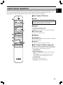
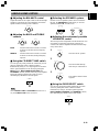
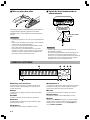
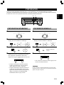
REMOTE CONTROL TRANSMITTER
The remote control transmitter provided with this unit is designed to control all the most commonly used functions of this
unit. If the CD player and tape deck connected to this unit are YAMAHA components designed for remote control
compatibility, this remote control transmitter will also control various functions of each component.
■ For Control of This Unit
1 POWER
Press this key to turn on this unit or turn it into the standby mode.
Standby mode
In this state, this unit consumes a very small quantity of power
to receive infrared-signals from the remote control.
2 Tuner keys
Control tuner.
+: Selects higher preset station number.
–: Selects lower preset station number.
A/B/C/D/E: Selects the group (A – E) of preset station numbers.
3 Input selector keys
Press a key to select the input source.
4 SLEEP key
Sets the sleep timer.
5 SPEAKERS A B
Turn on or off the set of main speakers connected to the A and/or B
terminals on the rear panel.
6 VOLUME + –
Press these keys to increase or decrease the volume.
■ For Control of Other Component
The functions of the keys to control other YAMAHA components
are the same as the corresponding keys on those components. Refer
to those components’ instruction manuals for details.
1 Tape deck keys
These keys control tape decks.
* DIR A, B and DECK A/B apply only to double cassette tape
decks.
* Pressing DIR A will reverse the tape direction on a single
cassette tape deck with the automatic reverse function.
2 CD player keys
These keys control compact disc players.
* DISC SKIP is used for disc changers only.
VOLUME
SPEAKER
TUNER
TAPE
CD
SLEEP
D–TV VCR
CDTUNER
PRESET
PHONO
DIR BDIR A
POWER
DISC SKIP
A/B/C/D/E
DECK
A/B
TAPE
DVD
BA
+
+
MD
/
1
2
3
4
6
1
2
5
CONTROLS AND THEIR FUNCTIONS

E-4
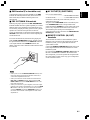
■ Battery installation
If you find that the remote control transmitter must be used
closer to the main unit, the batteries are weak. Replace both
batteries with new ones.
Notes
• Use only AA, R6, UM-3 batteries for replacement.
• Be sure the polarities are correct. (See the illustration inside the
battery compartment.)
• Remove the batteries if the remote control transmitter will not be
used for an extended period of time.
• If batteries leak, dispose of them immediately. Avoid touching
the leaked material or letting it come in contact with clothing,
etc. Clean the battery compartment thoroughly before installing
new batteries.
2
1
3
■ Remote control transmitter
operation range
Notes
• There should be no large obstacles between the remote control
transmitter and the main unit.
• If the remote control sensor is directly illuminated by strong
lighting (especially an inverter type of fluorescent lamp etc.), it
might cause the remote control transmitter not to work correctly.
In this case, reposition the main unit to avoid direct lighting.
NATURAL SOUND
BASS
PHONES
AB
STANDBY/ON
SPEAKERS
A/B/C/D/E 1 2 4 5 6 7 83
TREBLE BALANCE LOUDNESS
FLAT
TAPE/MD
DVD
D-TV
VCR
CD
TUNER
PHONO
AUTO/MAN'L MONO
1
2
4
5
3
6
7
8
9
0
2
4
8
12
16
20
28
40
60
–dB
10
0
11
2
4
5LR
3
5
4
3
2
0
11
2
4
5
3
5
4
3
2
0
11
2
4
5
———
—
—
—
3
5
4
3
2
-30%
TUNING MODE
REC OUT/ZONE 2
EDIT FM/AM
TUNING
DOWN UP
MEMORY
MAN'L/AUTO FM
INPUT
PURE
DIRECT
CD DIRECT
AMP
VOLUME
∞
STEREO
RECEIVER
RX–777
VCR · D-TV · DVD · TAPE/MD · TUNER · CD · PHONO
30°
30°
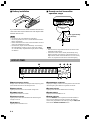
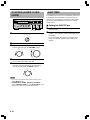
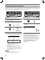
DISPLAY PANEL
1 Multi-information display
Displays various information, for example station frequency, preset
station number and name of selected input source.
2 AUTO indicator
Lights up when this unit is in the automatic tuning mode.
3 TUNED indicator
Lights up when turned in to a station.
4 STEREO indicator
Lights up when an FM stereo broadcast with sufficient signal
strength is received.
5 CD DIRECT
Lights up when CD DIRECT is on.
6 SPEAKERS A B indicator
Lights up according to which set of main speakers is selected. Both
indicators light up when both sets of speakers are selected.
7 SLEEP indicator
Lights up while the built-in SLEEP timer is functioning.
8 PURE DIRECT
Lights up when PURE DIRECT is on.
9 MEMO indicator
When the MEMORY button is pressed, this indicator flashes for
about 5 seconds. While this indicator is flashing, the displayed
station can be programmed to the memory by using the A/B/C/D/E
button and the PRESET STATIONS buttons.
Remote control
sensor
Within approximately
6 m (19.7 feet)
CONTROLS AND THEIR FUNCTIONS
AUTO
MH
Z
SLEEP
MEMO
SPEAKERS
STEREO
PURE
CD
DIRECT DIRECT
AB
TUNED
12345
7869
K
H
Z

E-5
English
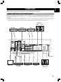
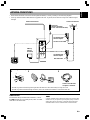
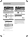
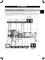
CONNECTIONS
Never plug in this unit and other components until all connections are completed.
CONNECTIONS WITH OTHER COMPONENTS
When making connections between this unit and other components, be sure all connections are made correctly, that is to say
L (left) to L, R (right) to R, “+” to “+” and “–” to “–”. Also, refer to the owner’s manual for each component to be connected
to this unit.
* If you have YAMAHA components numbered as !, #, $, etc. on the rear panel, connections can be made easily only by
connecting the output (or input) terminals of each component to the same-numbered terminals of this unit.
DVD player CD player D-TV
Speakers A
Right Left
Right LeftTurntableTape deckVideo cassette
recorder
Monitor TV
Speakers B
CONNECTIONS
To AC outlet
VIDEO SIGNALAUDIO SIGNAL
OUT
DVD
FM
ANT
PHONO
75Ω
UNBAL.
ZONE2
OUT
ZONE2
OUT
MONITOR
OUT
AM
ANT
GND
D–TV
VCR
IN
OUT
DVD
CD
REMOTE
CONTROL
COUPLER
SPEAKERS
CLASS 2 WIRING
: SEE INSTRUCTION MANUAL FOR CORRECT SETTING.
IMPEDANCE SELECTOR AC OUTLETS
SWITCHED
120V 60Hz
100W MAX. TOTAL
SET BEFORE POWER ON
D–TV
VCR
MAIN
IN
PRE
OUT
IN
IN
OUT
TAPE
/MD
IN
OUT
AUDIO SIGNAL GND
CAUTION
4ΩMIN./
SPEAKER
8ΩMIN./
SPEAKER
A OR B:
A + B:
6ΩMIN./
SPEAKER
12ΩMIN./
SPEAKER
A OR B:
A + B:
(
PLAY
)
(
REC
)
R
L
R
L
R
L
R
L
A
B
++––
1
3
4
VIDEO OUT
AUDIO OUT
VIDEO OUT
AUDIO OUT
OUTPUT
VIDEO IN
VIDEO IN
VIDEO OUT
AUDIO OUT
LINE IN
LINE OUT
OUTPUT
GND
AUDIO IN

E-6
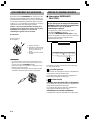
CONNECTING SPEAKERS
Connect the SPEAKERS terminals to your speakers with
wire of the proper gauge (cut as short as possible). If the
connections are faulty, no sound will be heard from the
speakers. Make sure that the polarity of the speaker wires is
correct, that is, + and – markings are observed. If these
wires are reversed, the sound will be unnatural and will lack
bass.
Do not let the bare speaker wires touch each other or the
metal parts of this unit as this could damage this unit
and/or speakers.
1 Unscrew the knob.
2 Insert the bare wire.
[Remove approx. 5mm (1/
4”) insulation from the
speaker wires.]
3 Tighten the knob and
secure the wire.
Notes
• One or two speaker systems can be connected to this unit. If you
connect only one speaker system, connect it to either the
SPEAKERS A or B terminals.
• Use speakers with the specified impedance shown on the rear of
this unit.
• Banana Plug connections are also possible. Simply insert the
Banana Plug connector into the corresponding terminal.
How to Connect:
Red: positive (+)
Black: negative (–)
REAR PANEL PARTS
■ IMPEDANCE SELECTOR switch
WARNING
Do not change the IMPEDANCE SELECTOR
switch setting while the power to this unit is on,
otherwise this unit may be damaged.
If this unit fails to turn on when the POWER switch is
pressed:
The IMPEDANCE SELECTOR switch may not be set
to either end. If so, set the switch to either end when this
unit’s power supply is completely cut off.
(Left position)
If you use one pair of speakers, the impedance of each
speaker must be 4Ω or higher.
If you use two pairs of speakers, the impedance of each
speaker must be 8Ω or higher.
(Right position)
<U.S.A. and Australia models>
If you use one pair of speakers, the impedance of each
speaker must be 6Ω or higher.
If you use two pairs of speakers, the impedance of each
speaker must be 12Ω or higher.
<Canada model only>
The impedance of each speaker must be 6Ω or higher.
IMPEDANCE SELECTOR
SET BEFORE POWER ON
4ΩMIN./
SPEAKER
8ΩMIN./
SPEAKER
A OR B:
A + B:
6ΩMIN./
SPEAKER
12ΩMIN./
SPEAKER
A OR B:
A + B:
Select the position whose requirements your speaker
system meets.
CONNECTIONS
<U.S.A. and Australia models>
2
1
3

E-7
English
CONNECTIONS
■ GND terminal (For turntable use)
Connecting the ground wire of the turntable to the GND
terminal will normally minimize hum, but in some cases
better results may be obtained with the ground wire
disconnected.
■ PRE OUT/MAIN IN terminals
Removing the jumper pins from the PRE OUT/MAIN IN
terminals enables this unit to operate separately as a control
amplifier and a power amplifier. These terminals are used
for connecting a signal-processing system such as a graphic
equalizer or a surround-sound processor to this unit.
If such an external unit is connected to these terminals, the
VOLUME control of this unit can be used for adjusting the
overall sound level.
To connect an external unit, first remove the jumper pins
from the PRE OUT/MAIN IN terminals, and then connect
the input terminals of that unit to the PRE OUT terminals
or its output terminals to the MAIN IN terminals. For
details, refer to the owner’s manual included with the unit to
be connected.
Notes
• When you do not use the PRE OUT/MAIN IN terminals, never
remove the jumper pins from these terminals. If removed, no
sound will be outputted from this unit.
• When you use this unit with an external unit connected to the
PRE OUT and MAIN IN terminals, make sure that the CD
DIRECT AMP switch and the PURE DIRECT switch on the
front panel are turned off.
• When you use this unit as a power amplifier, connect the output
terminals of an external control amplifier etc. to this unit’s MAIN
IN terminals. In this case, this unit’s controls will not function
except the PHONES jack and the SPEAKERS switches. Use
the controls on the external control amplifier to make volume
adjustment etc.
R
L
MAIN
IN
PRE
OUT
COUPLER
■ AC OUTLET(S) (SWITCHED)
(U.S.A. and Canada models)
............................................ 2 SWITCHED OUTLETS
(Australia model)........................ 1 SWITCHED OUTLET
Use these to connect the power cords from your A/V
components to this unit.
The power to the SWITCHED outlets is controlled by this
unit’s STANDBY/ON switch or the provided remote
control transmitter’s POWER key. These outlets will supply
power to any component whenever this unit is turned on.
The maximum power (total power consumption of
components) that can be connected to the SWITCHED AC
OUTLET(S) is 100 watts.
■ REMOTE CONTROL (IN, OUT)
terminals
These terminals are used for custom installation system.
When this unit is connected to the components for custom
installation system, you can operate this unit with the
system remote control.
Connect the REMOTE CONTROL IN terminal of this unit
to the output terminal of the central controller for custom
installation system.
By connecting the REMOTE CONTROL OUT terminal of
this unit to the REMOTE CONTROL IN terminal of the
other component, you can also operate the component with
the system remote control. In this way, up to 6 components
can be connected in series.

E-8
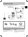
ZONE 2 CONNECTIONS
You can make up a multi-room audio-video system with this unit. This feature enables you to set this unit to reproduce
separate input sources in the main room and second room (Zone 2) with the supplied remote control in the second room.
To use the multi-room functions of this unit, you need the following additional equipment:
• An infrared signal receiver in the second room
• An infrared emitter in the main room
This emitter transmits the infrared signals from the remote control in the second room to the main room
(for example, to a CD player or LD player).
• An amplifier and speakers for the second room
• A video monitor for the second room
OUT IN OUT IN OUT IN
REMOTE CONTROL
y
• Since there are so many ways to connect and use this
unit in a multi-room installation, we recommend that
you consult with the nearest authorized YAMAHA
dealer or service center for the Zone 2 connections
which will best meet your requirements.
• Some YAMAHA models are able to connect directly
to the REMOTE CONTROL OUT terminal of this
unit. If you own these products, you may not need to
use an infrared emitter. Up to 6 YAMAHA
components can be connected as shown.
This unit
■ Example of a system configuration and connections
REMOTE CONTROL OUT REMOTE CONTROL IN
ZONE 2 VIDEO OUT
ZONE 2 AUDIO OUT
Main room
DVD player
(or other component)
This unit
Infrared emitter
Second room
Amplifier
Video
monitor
Remote control
(in the Zone 2 mode)
Infrared signal receiver

E-9
English
ANTENNA CONNECTIONS
• Each antenna should be connected to the designated terminal(s) correctly, referring to the following diagram.
• AM loop antena and indoor FM antena are supplied to this unit. In general, these antennas will provide sufficient signal
strength.
AUDIO SIGNAL
FM
ANT
PHONO
75Ω
UNBAL.
ZONE2
OUT
AM
ANT
GND
R
L
Outdoor FM antenna
AM loop
antenna
(included)
Indoor FM
antenna (included)
(U.S.A. and Canada models)
75-ohm/300-ohm
antenna adapter
75-ohm coaxial cable
75-ohm/300-ohm
antenna adapter
300-ohm feeder
Ground
Outdoor AM antenna
Connecting the AM loop antenna
* The AM loop antenna should be placed apart from the main unit. The antenna may be hung on a wall.
* The AM loop antenna should be kept connected, even if an outdoor AM antenna is connected to this unit.
12 3
Orient so that the best
reception is obtained.
ZONE 2 CONNECTIONS
GND terminal
For maximum safety and minimum interference, connect
the GND terminal to a good earth ground, which is a metal
stake driven into moist earth.
1
2
3
Note
A poperly installed outdoor antenna provides clearer reception than
an indoor one. If you experience poor reception quality, an outdoor
antenna may improve the quality. Consult the nearest authorized
YAMAHA dealer or service center about the outdoor antennas.

E-10
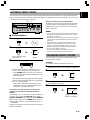
From page 10 to 15, this manual describes how to operate this unit mainly by using the front panel control parts.
To operate this unit on the remote control transmitter, use the corresponding keys on the remote control transmitter.
BASIC OPERATIONS
TO PLAY A SOURCE
NATURAL SOUND
BASS
PHONES
AB
STANDBY/ON
SPEAKERS
A/B/C/D/E 1 2 4 5 6 7 83
TREBLE BALANCE LOUDNESS
FLAT
TAPE/MD
DVD
D-TV
VCR
CD
TUNER
PHONO
AUTO/MAN'L MONO
1
2
4
5
3
6
7
8
9
0
2
4
8
12
16
20
28
40
60
–dB
10
0
11
2
4
5LR
3
5
4
3
2
0
11
2
4
5
3
5
4
3
2
0
11
2
4
5
———
—
—
—
3
5
4
3
2
-30%
TUNING MODE
REC OUT/ZONE 2
EDIT FM/AM
TUNING
DOWN UP
MEMORY
MAN'L/AUTO FM
INPUT
PURE
DIRECT
CD DIRECT
AMP
VOLUME
∞
STEREO
RECEIVER
RX–777
VCR · D-TV · DVD · TAPE/MD · TUNER · CD · PHONO
27
4 7 3 1, 6
1 Set to the “∞” position.
2 Turn the power on.
3 Select the desired input source by using the INPUT
selector. (For video sources, turn the TV/monitor
ON.)
* The name of the selected input source position will
appear on the display. (For “TUNER”, the tuning
mode will appear on the display.)
* Note that selecting each input source position selects
the source which is connected to the corresponding
input terminals on the rear panel.
4 Select the speakers to be used.
* If you use two speaker systems, press both the A and
B switches.
0
2
4
8
12
16
20
28
40
60
–dB
VOLUME
∞
STANDBY/ON
INPUT
VCR · D-TV · DVD · TAPE/MD · TUNER · CD · PHONO
5 Play the source. (For detailed information on the
tuning operation, refer to page 13.)
6 Adjust to the desired output level.
7 If desired, adjust the BASS, TREBLE, BALANCE
and LOUDNESS controls, etc. (Refer to page 11.)
When you finish using this unit
Press the STANDBY/ON switch on the front panel or
POWER key on the remote control transmitter again to turn
this unit into the standby mode.
AB
SPEAKERS
0
2
4
8
12
16
20
28
40
60
–dB
VOLUME
∞
POWER
SPEAKER
BA
VOLUME
+
D–TV VCR
CDTUNER PHONO
TAPE
DVD
MD
/

E-11
English
BASIC OPERATIONS
■ Adjusting the BALANCE control
Adjust the balance of the output volume to the left and right
speakers to compensate for sound imbalance caused from
speaker location or listening room conditions.
■ Adjusting the BASS and TREBLE
controls
BASS : Turn this clockwise to increase (or counter-
clockwise to decrease) the low frequency
response.
TREBLE : Turn this clockwise to increase (or counter-
clockwise to decrease) the high frequency
response.
■ Using the CD DIRECT AMP switch
You can enjoy the purest possible CD sound from your CD
player by setting this switch so that the indicator
illuminates. By doing so, CD’s input signals are sent to the
built-in special amplifier for CD directly bypassing the
INPUT selector, BASS, TREBLE, BALANCE and
LOUDNESS controls, and then sent to the power amplifier.
This signal routing reproduces the purest CD sound
eliminating any alterations to the CD signals.
Note
If both CD DIRECT AMP and PURE DIRECT switches are on,
only the CD DIRECT AMP switch will function.
VARIOUS SOUND CONTROL
BALANCE
0
11
2
4
5LR
3
5
4
3
2
BASS
0
11
2
4
5
——
—
3
5
4
3
2
TREBLE
0
11
2
4
5
3
5
4
3
2
——
—
CD DIRECT
AMP
■ Selecting the SPEAKER system
Because one or two speaker systems can be connected to
this unit, the SPEAKERS switches allow you to select
speaker system A or B, or both at once.
■ Adjusting the continuously variable
LOUDNESS control
This control provides compensation for the human ears’ loss
of sensitivity to high and low-frequency ranges at low
volume. This control is adjustable to retain full tonal range
at any volume level.
1
2
3
■ Using the PURE DIRECT switch
You can enjoy the purest possible sound from your audio
sources by setting this switch so that the indicator
illuminates. By doing so, the audio signals bypass the
BASS, TREBLE, BALANCE and LOUDNESS controls,
thus eliminating any alteration to the audio signals.
AB
SPEAKERS
SPEAKER
BA
Set to the “FLAT” position.
LOUDNESS
FLAT
1
2
4
5
3
6
7
8
9
10
-30%
0
2
4
8
12
16
20
28
40
60
–dB
VOLUME
∞
Set to the loudest listening
level that you would listen in.
Turn until the desired volume
is gained.
LOUDNESS
FLAT
1
2
4
5
3
6
7
8
9
10
-30%
PURE
DIRECT

E-12
TO RECORD A SOURCE TO TAPE
(OR MD)
BASIC OPERATIONS
1 Select the source you want to record.
2 Play the source.
3 Confirm the source by selecting it with the INPUT
selector and turning up the VOLUME control.
4 Begin recording on the tape deck (or MD recorder
etc.) or VCR connected to this unit.
5 To monitor the sound (and/or picture) to be
recorded, select the tape deck (or VCR) being
used for recording with the INPUT selector.
Notes
• If you want to enjoy another source while recording, select it
with the INPUT selector.
• VOLUME, BASS, TREBLE, BALANCE, LOUDNESS
controls, CD DIRECT AMP switch and PURE DIRECT switch
settings have no effect on the material being recorded.
NATURAL SOUND
BASS
PHONES
AB
STANDBY/ON
SPEAKERS
A/B/C/D/E 1 2 4 5 6 7 83
TREBLE BALANCE LOUDNESS
FLAT
TAPE/MD
DVD
D-TV
VCR
CD
TUNER
PHONO
AUTO/MAN'L MONO
1
2
4
5
3
6
7
8
9
0
2
4
8
12
16
20
28
40
60
–dB
10
0
11
2
4
5LR
3
5
4
3
2
0
11
2
4
5
3
5
4
3
2
0
11
2
4
5
———
—
—
—
3
5
4
3
2
-30%
TUNING MODE
REC OUT/ZONE 2
EDIT FM/AM
TUNING
DOWN UP
MEMORY
MAN'L/AUTO FM
INPUT
PURE
DIRECT
CD DIRECT
AMP
VOLUME
∞
STEREO
RECEIVER
RX–777
VCR · D-TV · DVD · TAPE/MD · TUNER · CD · PHONO
133, 5
TAPE/MD
DVD
D-TV
VCR
CD
TUNER
PHONO
REC OUT/ZONE 2
INPUT
VCR · D-TV · DVD · TAPE/MD · TUNER · CD · PHONO
0
2
4
8
12
16
20
28
40
60
–dB
VOLUME
∞
INPUT
VCR · D-TV · DVD · TAPE/MD · TUNER · CD · PHONO
SLEEP TIMER
The SLEEP timer can be used to automatically set this unit
in the standby mode. This timer is useful when you are
going to sleep while enjoying a broadcast or other desired
input source. The SLEEP timer can only be set with the
remote control.
■ Setting the SLEEP Timer
1 Play a source you want to enjoy when you are
going to sleep.
2 Press the SLEEP key to set the sleep timer (60
minutes). The “SLEEP” indicator soon lights up on
the display.
Press the SLEEP key again to cancel the sleep
timer. The “SLEEP” indicator goes off from the
display.

E-13
English
TUNING OPERATIONS
Normally, if station signals are strong and there is no interference, quick automatic-search tuning (AUTOMATIC TUNING)
is possible. However, if signals of the station you want to select are weak, you must tune to it manually (MANUAL
TUNING).
AUTOMATIC TUNING
1 Select “TUNER” as the input source.
2 Select the reception band (FM or AM) confirming it
on the display.
3
4 To tune to a higher frequency, press the right side
once.
To tune to a lower frequency, press the left side
once.
* If the station where tuning search stops is not the
desired one, press again.
* If the tuning search does not stop at the desired
station (because the signals of the station are weak),
change to the MANUAL TUNING method.
MANUAL TUNING
1 Select “TUNER” as the input source.
2 Select the reception band (FM or AM) confirming it
on the display.
3
4 Tune to a desired station manually.
* To continue tuning search, hold down the button.
Note
If you tune to an FM station manually, it is received in monaural
mode automatically to increase the signal quality.
NATURAL SOUND
BASS
PHONES
AB
STANDBY/ON
SPEAKERS
A/B/C/D/E 1 2 4 5 6 7 83
TREBLE BALANCE LOUDNESS
FLAT
TAPE/MD
DVD
D-TV
VCR
CD
TUNER
PHONO
AUTO/MAN'L MONO
1
2
4
5
3
6
7
8
9
0
2
4
8
12
16
20
28
40
60
–dB
10
0
11
2
4
5LR
3
5
4
3
2
0
11
2
4
5
3
5
4
3
2
0
11
2
4
5
———
—
—
—
3
5
4
3
2
-30%
TUNING MODE
REC OUT/ZONE 2
EDIT FM/AM
TUNING
DOWN UP
MEMORY
MAN'L/AUTO FM
INPUT
PURE
DIRECT
CD DIRECT
AMP
VOLUME
∞
STEREO
RECEIVER
RX–777
42
31
VCR · D-TV · DVD · TAPE/MD · TUNER · CD · PHONO
INPUT
VCR · D-TV · DVD · TAPE/MD · TUNER · CD · PHONO
FM/AM
AUTO/MAN'L MONO
TUNING MODE
TUNING
DOWN UP
INPUT
VCR · D-TV · DVD · TAPE/MD · TUNER · CD · PHONO
FM/AM
AUTO/MAN'L MONO
TUNING MODE
TUNING
DOWN UP
Turn the “AUTO”
indicator off.
AUTO
or or

E-14
MANUAL PRESET TUNING
This unit can store station frequencies selected by tuning operation. With this function, you can recall any desired station only
by selecting the preset station number where it is stored. Up to 40 stations (8 stations x 5 groups) can be stored.
NATURAL SOUND
BASS
PHONES
AB
STANDBY/ON
SPEAKERS
A/B/C/D/E 1 2 4 5 6 7 83
TREBLE BALANCE LOUDNESS
FLAT
TAPE/MD
DVD
D-TV
VCR
CD
TUNER
PHONO
AUTO/MAN'L MONO
1
2
4
5
3
6
7
8
9
0
2
4
8
12
16
20
28
40
60
–dB
10
0
11
2
4
5LR
3
5
4
3
2
0
11
2
4
5
3
5
4
3
2
0
11
2
4
5
———
—
—
—
3
5
4
3
2
-30%
TUNING MODE
REC OUT/ZONE 2
EDIT FM/AM
TUNING
DOWN UP
MEMORY
MAN'L/AUTO FM
INPUT
PURE
DIRECT
CD DIRECT
AMP
VOLUME
∞
STEREO
RECEIVER
RX–777
VCR · D-TV · DVD · TAPE/MD · TUNER · CD · PHONO
243
NATURAL SOUND
BASS
PHONES
AB
STANDBY/ON
SPEAKERS
A/B/C/D/E 1 2 4 5 6 7 83
TREBLE BALANCE LOUDNESS
FLAT
TAPE/MD
DVD
D-TV
VCR
CD
TUNER
PHONO
AUTO/MAN'L MONO
1
2
4
5
3
6
7
8
9
0
2
4
8
12
16
20
28
40
60
–dB
10
0
11
2
4
5LR
3
5
4
3
2
0
11
2
4
5
3
5
4
3
2
0
11
2
4
5
———
—
—
—
3
5
4
3
2
-30%
TUNING MODE
REC OUT/ZONE 2
EDIT FM/AM
TUNING
DOWN UP
MEMORY
MAN'L/AUTO FM
INPUT
PURE
DIRECT
CD DIRECT
AMP
VOLUME
∞
STEREO
RECEIVER
RX–777
VCR · D-TV · DVD · TAPE/MD · TUNER · CD · PHONO
12
■ To store stations
1 Tune to a desired station.
(Refer to the previous page for tuning procedure.)
2 Select a desired group (A – E) of preset stations
confirming it on the display.
3
4 Select a preset station number where you want to
program the station before the “MEMO” indicator
goes off from the display.
* In the same way, program other stations to A2, A3 ...
A8.
* You can program more stations to preset station
numbers of other groups in the same way by
selecting other groups in step 2.
Note
• A new setting can be programmed in place of the former one.
■ To recall a preset station
1 Select the group of preset stations.
2 Select the preset station number.
Memory back-up
The memory back-up circuit prevents the programmed data
from being lost even if this unit is turned into the standby
mode or the power plug is disconnected from the AC outlet
or the power is cut due to temporary power failure. If,
however, the power is cut for more than one week, the
memory may be erased. If so, it can be re-programmed by
simply following the MANUAL/AUTOMATIC PRESET
TUNING steps.
A/B/C/D/E
MEMORY
MAN'L/AUTO FM
A/B/C/D/E
12 456783
TUNING OPERATIONS
A/B/C/D/E
PRESET
+
MEMO
12 4 567 83
MH
Z
Flashes on and off for
about 5 seconds.
Shows the displayed station has
been programmed to A1.

E-15
English
AUTOMATIC PRESET TUNING
You can make use of an automatic preset tuning function for FM stations. With this function, this unit performs automatic
tuning and stores FM stations with strong signals sequentially. Up to 40 stations are stored automatically in the same way as
in the manual preset tuning method on page 14.
NATURAL SOUND
BASS
PHONES
AB
STANDBY/ON
SPEAKERS
A/B/C/D/E 1 2 4 5 6 7 83
TREBLE BALANCE LOUDNESS
FLAT
TAPE/MD
DVD
D-TV
VCR
CD
TUNER
PHONO
AUTO/MAN'L MONO
1
2
4
5
3
6
7
8
9
0
2
4
8
12
16
20
28
40
60
–dB
10
0
11
2
4
5LR
3
5
4
3
2
0
11
2
4
5
3
5
4
3
2
0
11
2
4
5
———
—
—
—
3
5
4
3
2
-30%
TUNING MODE
REC OUT/ZONE 2
EDIT FM/AM
TUNING
DOWN UP
MEMORY
MAN'L/AUTO FM
INPUT
PURE
DIRECT
CD DIRECT
AMP
VOLUME
∞
STEREO
RECEIVER
RX–777
VCR · D-TV · DVD · TAPE/MD · TUNER · CD · PHONO
23 1
■ To store stations
1
2
3
To tune to higher frequencies, press right side once.
To tune to lower frequencies, press left side once.
* If the TUNING button is not pressed, in a while, the
automatic preset tuning begins automatically toward
higher frequencies.
The automatic preset tuning begins from the frequency
currently displayed. Received stations are programmed
to A1, A2 ... A8 sequentially.
* If more than 8 stations are received, they are also
programmed to the preset station numbers of other
groups (B, C, D and E) in that order.
If you want to store the first station received by the
automatic preset tuning to a desired preset station
number;
If, for example, you want to store the first received station to
C5, select “C5” by using the A/B/C/D/E button and the
PRESET STATIONS buttons after pressing the MEMORY
button in step 2. Then press the TUNING button. The first
received station is stored to C5, and next stations to C6, C7
... sequentially.
If stations are stored up to E8, the automatic preset tuning is
finished automatically.
FM/AM
MEMORY
MAN'L/AUTO FM
TUNING
DOWN UP
When the automatic preset tuning is finished;
The display shows the frequency of the last preset station.
Check the contents and the number of preset stations by
following the procedure of the section “To recall a preset
station” on page 14.
Notes
• You can replace a preset station by another FM or AM station
manually by simply following the procedure of the section “To
store stations” on page 14.
• If the number of received stations is not enough to be stored up
to E8, the search is finished automatically after searching all
frequencies.
• With this function, only FM stations with sufficient signal
strength are stored automatically. If the station you want to
program is weak in signal strength, tune to it in monaural
manually and program it by following the procedure of the
section “To store stations” on page 14.
• For presets, the setting of the reception mode (stereo or
monaural) is stored along with the station frequency.
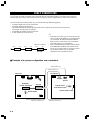
EXCHANGING PRESET STATIONS
You can exchange the places of two preset stations with
each other as shown below.
Example)
If you want to shift the preset station on E1 to A5.
1 Recall the preset station on E1 (by following the
method of “To recall a preset station” on page 14).
2
3 Recall the preset station on A5 by following the
same method as in step 1.
4
Press and hold for more
than 3 seconds.
EDIT
EDIT
TUNING OPERATIONS
MEMO
MEMO
MEMO
Flashes.
Flashes.
Shows the exchange of
stations is completed.

E-16
TROUBLESHOOTING
If the unit fails to operate normally, check the following points to determine whether the fault can be corrected by the simple
measures suggested. If it cannot be corrected, or if the fault is not listed in the PROBLEM column, disconnect the power cord
and contact your authorized YAMAHA dealer or service center for help.
PROBLEM
Amplifier
The unit fails to turn on when the STANDBY/
ON switch is pressed.
It happens that this unit does not work
normally.
No sound or no picture.
The sound suddenly goes off.
Only one side speaker outputs the sound.
Sound “hums”.
The volume level is low while playing a record.
The volume level cannot be increased, or sound
is distorted.
Sound level is low.
The INPUT selector will not function though it
is turned.
Using the BASS, TREBLE, BALANCE and
LOUDNESS controls does not affect the tone.
FM
FM stereo reception is noisy.
There is distortion and clear reception cannot be
obtained even with a good FM antenna.
A desired station cannot be tuned in with the
automatic tuning method.
Previously preset stations can no longer be
tuned in.
AM
A desired station cannot be tuned in with the
automatic tuning method.
There are continuous crackling and hissing
noises.
There are buzzing and whining noises (especially
in the evening).
CAUSE
Power cord is not plugged in or is not completely
inserted.
There is an influence of strong external noise
(lightning, excessive static electricity, etc.) or a
misoperation on this unit while using this unit.
Incorrect output cord connections.
Appropriate input source is not selected.
The SPEAKERS switches are not set properly.
Speaker connections are not secure.
The protection circuit has been activated because of
short circuit etc.
The SLEEP timer has functioned.
Incorrect setting of the BALANCE control.
Incorrect cord connections.
Incorrect cord connections.
No connection from the turntable to the GND
terminal.
The record is being played on a turntable with an
MC cartridge.
The component connected to the REC or ZONE 2
output terminals of this unit is turned off.
The LOUDNESS control is functioning.
The CD DIRECT AMP switch is ON.
The CD DIRECT AMP or PURE DIRECT switch
is ON.
Because of the characteristics of FM stereo
broadcasts, this is limited to cases where the
transmitter is too far away or the antenna input is
poor.
There is multipath interference.
The station is too weak.
This unit has been unplugged for a long period.
Weak signal or loose antenna connections.
Noises result from ligtning, fluorescent lamps,
motors, thermostats and other electrical equipment.
A television set is being used nearby.
REMEDY
Firmly plug in the power cord.
Turn this unit into the standby mode and disconnect
the AC power cord from the AC outlet. After about
30 seconds pass, connect the power and operate this
unit again.
Connect the cords properly. If the problem persists,
the cords may be defective.
Select an appropriate input source with the INPUT
selector.
Set the SPEAKERS switch which corresponds to
the speakers to be used to the ON position.
Secure the connections.
Check the IMPEDANCE SELECTOR switch is set
to the appropriate position and then turn the unit
back on.
Check the speaker wires are not touching each
other and then turn the unit back on.
Turn on the power, and play the source again.
Adjust it to the appropriate position.
Connect the cords properly. If the problem persists,
the cords may be defective.
Firmly connect the audio plugs. If the problem
persists, the cords may be defective.
Make the GND connection between the turntable
and this unit.
The player should be connected to the unit through
the MC head amplifier.
Turn the power to the component on.
Set the LOUDNESS control to the 0 position.
Switch off the CD DIRECT AMP switch.
The CD DIRECT AMP and PURE DIRECT
switches must be switched OFF to use those
controls.
Check the antenna connections.
Try using a high quality directional FM antenna.
Set the TUNING MODE button to the manual
tuning mode.
Adjust antenna placement to eliminate multipath
interference.
Use the manual tuning method.
Use a high quality directional FM antenna.
Repeat the presetting procedure.
Tighten the AM loop antenna connections and
rotate it for best reception.
Use the manual tuning method.
Use an outdoor antenna and a ground wire. This
will help somewhat but it is difficult to eliminate all
the noises.
Relocate this unit away from the TV.
La pagina si sta caricando...
La pagina si sta caricando...
La pagina si sta caricando...
La pagina si sta caricando...
La pagina si sta caricando...
La pagina si sta caricando...
La pagina si sta caricando...
La pagina si sta caricando...
La pagina si sta caricando...
La pagina si sta caricando...
La pagina si sta caricando...
La pagina si sta caricando...
La pagina si sta caricando...
La pagina si sta caricando...
La pagina si sta caricando...
La pagina si sta caricando...
La pagina si sta caricando...
La pagina si sta caricando...
La pagina si sta caricando...
La pagina si sta caricando...
-
 1
1
-
 2
2
-
 3
3
-
 4
4
-
 5
5
-
 6
6
-
 7
7
-
 8
8
-
 9
9
-
 10
10
-
 11
11
-
 12
12
-
 13
13
-
 14
14
-
 15
15
-
 16
16
-
 17
17
-
 18
18
-
 19
19
-
 20
20
-
 21
21
-
 22
22
-
 23
23
-
 24
24
-
 25
25
-
 26
26
-
 27
27
-
 28
28
-
 29
29
-
 30
30
-
 31
31
-
 32
32
-
 33
33
-
 34
34
-
 35
35
-
 36
36
-
 37
37
-
 38
38
-
 39
39
-
 40
40


Yamaha RX-777 Manuale utente
- Categoria
- Sintonizzatori audio
- Tipo
- Manuale utente
in altre lingue
- English: Yamaha RX-777 User manual
- français: Yamaha RX-777 Manuel utilisateur
- español: Yamaha RX-777 Manual de usuario
- Deutsch: Yamaha RX-777 Benutzerhandbuch
- русский: Yamaha RX-777 Руководство пользователя
- Nederlands: Yamaha RX-777 Handleiding
- português: Yamaha RX-777 Manual do usuário
- dansk: Yamaha RX-777 Brugermanual
- čeština: Yamaha RX-777 Uživatelský manuál
- polski: Yamaha RX-777 Instrukcja obsługi
- svenska: Yamaha RX-777 Användarmanual
- Türkçe: Yamaha RX-777 Kullanım kılavuzu
- suomi: Yamaha RX-777 Ohjekirja
- română: Yamaha RX-777 Manual de utilizare
Documenti correlati
-
Yamaha R-302 Manuale utente
-
-
-
-
-
-
-
-
-