MULTIFUNCTION
CABLE TESTER
INSTRUCTIONS
MODEL 351898
INT-351898-UM-ML1-0814-03
FRANÇAIS Testeur de câbles multifonction
REMARQUE: Assurez-vous qu’une pile 9 volts a été installé
dans le compartiment de la batterie. ATTENTION: Ne pas
brancher le testeur de câble pour vivre circuits: Il peut être
endommagé par une tension élevée.
1 Appuyez sur le bouton d’alimentation (A) à la position de
marche (On). La DEL d’alimentationr (B) clignotera pour
indiquer que le périphérique est alimenté correctement.
2 Pour tester câble modulaire USOC 4/6/8, connecter une
extrémité du câble à l’appareil de contrôle de maître (C)
et l’autre extrémité à l’unité distante (D). (Vous pouvez
relier les deux extrémités de l’unité principale si vous ne
faites pas un test à distance.) Dès que le câble est inséré,
le testeur va commencer à balayer les paires de broches
de connecteur (E).
3 Appuyez sur le bouton de test (F).
•
Si le test de broches du câble correct, la DEL correspondant
sur chaque unité de test à usage s’allume en vert.
• Si les DEL sont rouges , le câble a été câblé en sens
inverse.
• Si les DEL sont verts d’abord, puis rouge (mixte) ou
reste éteint, le câble est mauvais.
Vous trouvez les spécifications sur intellinet-network.com.
ESPAÑOL Probador de Cables Multifuncional
NOTA: Asegúrese de colocar una batería de 9 volts en el compartimento. PRECAUCIÓN: No conecte el probador
de cables a un circuito activo; podría generar un daño por alto voltaje.
1 Presione el botón (A) a la posición de encendido “ON”. El led de encendido (B) se iluminará para indicar que el
dispositivo está alimentado correctamente.
2 Para la prueba USOC 4/6/8 de cable modular (RJ11 y RJ45), conecte uno de los extremos del cable a probador
maestro (C) y el otro extremo a la unidad remota (D). (Usted puede conectar ambos extremos al probador
maestro si no está realizando una prueba remota). Tan pronto el cable sea insertado, el probador comenzará a
escanear los pares por medio de los pines del conector (E).
3 Presione el botón de prueba (F).
• Si los pines en el cable funcionan, los LED correspondientes en cada unidad se encenderán en color verde.
• Si los LED encienden en color rojo, el cable se ha colocado en una posición errónea.
• Si los LED encienden inicialmente en color verde y cambian a color rojo (mezclándose) o permanecen
apagados, el cable no funciona.
Para más especificaciones, visite intellinet-network.com.
POLSKI Tester okablowania wielofunkcyjny
UWAGA: Upewnij się, że bateria 9V została zainstalowana w
komorze baterii. UWAGA: Nie wolno podłączać testera
okablowania do obwodów – urządzenie może zostać
uszkodzone przez wysokie napięcie.
1 Wciśnij przycisk zasilania (A) w pozycję ON. Dioda
sygnalizacyjna zasilania Power (B) będzie migać sygnalizując,
że urządzenie jest poprawnie zasilane.
2 Aby przetestować kabel modularny USOC 4/6/8 (RJ11 i RJ45),
podłącz jeden koniec kabla do testera głównego „master” (C),
a drugi koniec do pilota zdalnego sterowania (D). (Można
połączyć oba końce do jednostki nadrzędnej „master”, jeśli
nie robisz zdalnego testu). Jak tylko kabel jest włożony,
tester rozpocznie skanowanie par pinów połączeniowych (E).
3 Naciśnij przycisk Test (F).
• Jeśli test pinów kabla jest prawidłowy, odpowiednia dioda
LED na każdej jednostce testera będącej w użyciu świeci na
zielono.
•
Jeżeli diody LED świecą na czerwono, piny zostały zarobione
w odwrotnej kolejności.
• Jeśli diody LED świecą naprzemiennie.
Pełną specyfikację produktu znajdziecie Państwo na stronie
intellinet-network.com.
ITALIANO Tester per cavi di rete multifunzione
NOTA: Assicurarsi che la batteria da 9-volt sia stata installata
correttamente all’interno del comparto batterie. ATTENZIONE:
Non connettere il tester per cavi a circuiti sotto tensione :
potrebbe venire danneggiato dall’alto voltaggio.
1 Premere il tasto di accensione (A) e posizionarlo su On. Il LED
di alimentazione (B) lampeggerà ad indicare che la periferica
è correttamente alimentata.
2 Per testare cavi modulari USOC 4/6/8 (RJ11 & RJ45), collegare
un capo del cavo al master tester (C) e l’altro capo all’unità
remota (D). (Potete collegare entrambi i lati del cavo all’unità
master se non dovete fare un test remoto.) Appena il cavo è
inserito, il tester inizierà ad esaminare le coppie dei pin del
connettore (E).
3 Premere il tasto di Test (F).
• Se l’esame della pinatura del cavo è okay, il corrispondente
LED su ciascuna unità di tester in uso si illuminerà in verde.
• Se i LED si illuminano in rosso, il cavo è stato cablato al
contrario.
• Se i LED si illuminano prima in verde e poi in rosso (in modo
vario) o rimangono spenti, il risultato del test è negativo e il
cavo non funziona.
Per ulteriori specifiche, visita il sito intellinet-network.com.
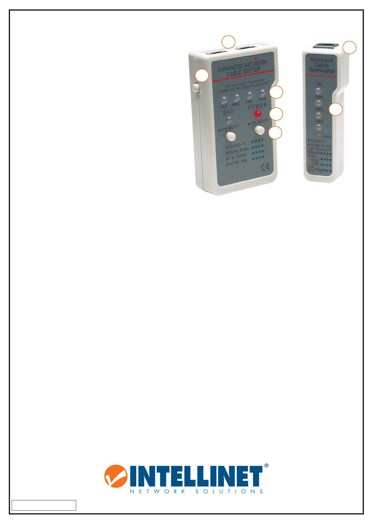
NOTE: Make sure a 9-volt battery has been installed in the battery compartment.
CAUTION: Don’t connect the cable tester to live circuits: It can be damaged by high voltage.
1 Press the Power button (A) to the On position. The Power LED (B) will flash to indicate the
device is powered properly.
2 To test USOC 4/6/8 modular cable (RJ11 & RJ45), connect one end of the cable to the master
tester (C) and the other end to the remote unit (D). (You can connect both ends to the master
unit if you’re not doing a remote test.) As soon as the cable is inserted, the tester will start to
scan through pairs of connector pins (E).
3 Press the Test button (F).
• If the cable pins test okay, the corresponding LED on each tester unit in use will light green.
• If the LEDs light red, the cable has been wired in reverse.
• If the LEDs light green first and then red (mixed) or remain unlit, the cable is bad.
For specifications, go to intellinet-network.com.
C
DEUTSCH Multifunktions Kabeltester
HINWEIS: Eine 9-Volt-Batterie muss in das Batteriefach eingesetzt werden
vor Inbetriebnahme. ACHTUNG: Schließen Sie das Kabel Tester niemals an
Spannungsquellen an. Das Gerät kann durch die hohe Spannungen
beschädigt werden.
1 Schalten Sie das Gerät ein indem Sie die Power-Taste (A) drücken. Die
Power-LED (B) blinkt, wenn das Gerät ordnungsgemäß eingeschaltet ist.
2 Um USOC 4/6/8 modulare Kabel zu Testen (RJ11 & RJ45), verbinden Sie
ein Ende des Kabels mit dem Master-Tester (C) und das andere Ende mit
Einheit (D). (Sie können beide Enden mit dem Master-Gerät anschliessen
,
falls Sie keinen Remote-Test durchführen möchten.) Sobald das Kabel
eingeführt wird, wird der Test beginnen (E).
3 Drücken Sie die Test-Taste (F).
• Wenn die Kabel Pins erfolgreich getestet wurden, leuchten die
entsprechenden LEDs grün auf.
• Wenn die LEDs rot leuchten, dann ist die Kabel-Belegung verkehrt
(umgekehrter verdrahtet).
• Wenn die LEDs im Wechsel grün und rot aufleuchten, oder sie leuchten
garnicht auf, dann ist das Kabel defekt.
Die Spezifikationen finden Sie auf intellinet-network.com.
intellinet-network.com
Important: Read before use.
Importante: Leer antes de usar.
E
E
F
B
A
D
