Vertex Standard 8x8 HDMI-HDBaseT Matrix Switcher Istruzioni per l'uso
- Tipo
- Istruzioni per l'uso

VX-5500
OPERATING MANUAL
POWER
VERTEX STANDARD CO., LTD.
4-8-8 Nakameguro, Meguro-Ku, Tokyo 153-8644, Japan
VERTEX STANDARD
US Headquarters
10900 Walker Street, Cypress, CA 90630, U.S.A.
International Division
8350 N.W. 52nd Terrace, Suite 201, Miami, FL 33166, U.S.A.
YAESU EUROPE B.V.
P.O. Box 75525, 1118 ZN Schiphol, The Netherlands
YAESU UK LTD.
Unit 12, Sun Valley Business Park, Winnall Close
Winchester, Hampshire, SO23 0LB, U.K.
VERTEX STANDARD HK LTD.
Unit 5, 20/F., Seaview Centre, 139-141 Hoi Bun Road,
Kwun Tong, Kowloon, Hong Kong

Congratulations!
You now have at your fingertips a valuable communications tool - a two-way
radio! Rugged, reliable and easy to use, your radio will keep you in constant
touch with your colleagues for years to come, with negligible maintenance down time.
Please take a few minutes to read this manual carefully. The information presented here
will allow you to derive maximum performance from your radio. After reading it, keep
the manual handy for quick reference, in case questions arise later on.
We’re glad you joined the team. Call on us any time, because our business is
communications. Let us help you get your message across.
NOTICE
There are no user-serviceable points inside this transceiver. All service jobs must
be referred to your Authorized Service Center or Network Administrator.
Safety / Warning Information
WARNING - DO NOT operate the VX-5500V radio when someone (bystanders)
outside the vehicle is within following range.
Safety Training information:
Antennas used for this transmitter must not exceed an antenna gain of 0 dBd. The
radio must be used in vehicle-mount configurations with a maximum operating duty
factor not exceeding 50%, in typical Push-to-Talk configurations.
This radio is restricted to occupational use, work related operations only where the
radio operator must have the knowledge to control the exposure conditions of its
passengers and bystanders by maintaining the minimum separation distance of
following range.
Failure to observe these restrictions will result in exceeding the FCC RF exposure
limits.
Antenna Installation:
For rear deck trunk installation, the antenna must be located at least the following
range away from rear seat passengers and bystanders in order to comply with the
FCC RF exposure requirements.
For roof top installation, the antenna must be placed in the center of the roof.
Radiated frequency and Distance
VX-5500V (C)
1.97 Feet
(0.6 m)

Page 1
VX-5500 Operating Manual
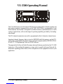
VX-5500 Operating Manual
The VX-5500 Series are full-featured FM transceivers designed for flexible mobile and
base station business communications in the VHF (50/10 Watts: programmable) Land
Mobile Bands. Each model is designed for reliable business communications in a wide
variety of applications, with a wide range of operating capability provided by its leading-
edge design.
The 250-channels memories can each be programmed with a 8-character channel name.
Important channel frequency data is stored in EEPROM and flash memory on the CPU,
and is easily programmable by dealers using a personal computer and the VERTEX STAN-
DARD CT-71 Programming Cable and CE49 Software.
The pages which follow will detail the many advanced features provided on the VX-5500
transceiver. After reading this manual, you may wish to consult with your Network Ad-
ministrator regarding precise details of the configuration of this equipment for use in your
application.
POWER

Page 2 VX-5500 Operating Manual
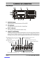
CONTROLS & CONNECTORS
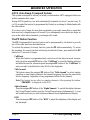
Front Panel
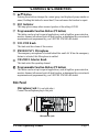
ÀPOWER Botton
Press the button to turn the transceiver ON and OFF.
ÁTX Indicator
This lamp glows red when the radio is transmitting.
ÂBUSY Indicator
This lamp glows green when the channel is busy.
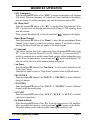
ÃLiquid Crystal Display
The display include an 8-character alpha-numeric section showing channel and group
names, status and identity information, and error messages. Additional indicators on
the display show priority channel assignments and scan include / exclude selection.
POWER
ƒ
‚
„
…
‡
ˆ
‰
Š
†
•
8 Character Alpha-numeric Display
Channel Group Number
This channel on “INTERCOM” ListThis channel on “SELECTABLE TONE” List
This channel on “SCAN” List
Receiver MonitorThis channel on “PUBLIC ADDRESS” or
“SPEAKER” List
This channel on “HORN ALERT” List
This channel on
“OPTION” List
This channel on “AUX A/B/C” List

Page 3
VX-5500 Operating Manual
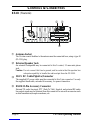
Äp/q Button
Pressing these buttons changes the current group (and displayed group number or
name). Holding this button for more than 1/2 second causes the function to repeat.
ÅSQC Indicator
This lamp glows orange when incorrect position at the setting of CE49.
ÆProgrammable Function Button (PF button)
This button can be set up for special applications, such as high/low power selection,
monitor, dimmer, talk-around, and call alert function, as determined by your network
requirements and programmed by your VERTEX STANDARD dealer.
ÇVOLUME Knob
This knob sets the volume of the receiver.
ÈEMERGENCY Microphone
The emergency microphone is located behind this small slit. When the emergency
feature is activated, this Microphone is enabled.
ÉCHANNEL Selector Knob
This knob select the operating channel.
Programmable Function Button (PF button)
This button can be set up for special applications, such as high/low power selection,
monitor, dimmer, talk-around, and call alert function, as determined by your network
requirements and programmed by your VERTEX STANDARD dealer.
Side Panel
Microphone Jack (It is on both sides.)
Connect the microphone plug to this jack.
CONTROLS & CONNECTORS
Microphone Jack

Page 4 VX-5500 Operating Manual
ƒ
‚
•
„
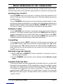
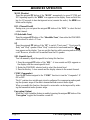
REAR (Heatsink)
ÀAntenna Socket
The 50-ohm coaxial feedline to the antenna must be connected here, using a type-M
(PL-259) plug.
ÁExternal Speaker Jack
An external loudspeaker may be connected to this 2-contact, 3.5-mm mini-phone
jack.
Caution: Do not connect this line to ground, and be certain that the speaker has
adequate capability to handle the audio output from the VX-5500.
Â13.8-V DC Cable Pigtail w/Connector
The supplied DC power cable must be connected to this 2-pin connector. Use only
the supplied fused cable, extended if necessary, for power connection.
ÃDSUB 25-Pin Accessory Connector
External TX audio line input, PTT (Push To Talk), Squelch, and external RX audio
line output signal may be obtained from this connector for use with accessories such
as data transmission/reception modems, ets.
CONTROLS & CONNECTORS

Page 5
VX-5500 Operating Manual
BASIC OPERATION OF THE TRANSCEIVER
Important! - Before turning on the radio the first time, confirm that the power connec-
tions have been made correctly and that a proper antenna is connected to the antenna jack.
Switching Power ON/OFF
Push the POWER switch turn on the radio. The display will become illuminated. The
radio will start up on the last channel used prior to shut-down during the previous
operating session.
Turn the CHANNEL selector knob to choose the desired operating channel. A chan-
nel name will appear on the display. If you want to select the operating channel from a
different Memory Channel Group, press the UP (p) or DOWN (q) button to select
the Memory Channel Group you want before selecting the operating channel.
Setting the Volume
Turn the VOLUME knob clockwise to increase the volume, and counterclockwise to
decrease it. If no signal is present, press and hold in the MON button more than 1/2
seconds; background noise will now be heard, and you may use this to set the VOL-
UME knob for the desired audio level. Press and hold the MON button more than 1/2
seconds to quiet the noise and resume normal (quiet) monitoring.
Transmitting
To transmit, wait until the “BUSY” indicator is off (the channel is not in use), and
press the PTT (Push-To-Talk) switch on the side of the microphone (the “TX” indica-
tor will appear or the “TX” indicator will glow red). While holding in the PTT switch,
speak across the face of the microphone in a clear, normal voice level, and then release
the PTT switch to receive.
Selecting Groups and Channels
m Press the UP (p) or DOWN (q) button (repeatedly, if necessary) to select a
different group of channels.
m Turn the CHANNEL selector knob to select a different channel within the current
group.
Automatic Time-Out Timer
If the selected channel has been programmed for automatic time-out, you must limit
the length of each transmission. While transmitting, a beep will sound five seconds
before time-out. Another beep will sound just before the deadline; the “TX” indicator
will disappear and transmission will cease soon thereafter. To resume transmitting,
you must release the PTT and wait for the “penalty timer” to expire (if you press the
PTT before this timer expires, the timer restarts, and you will have to wait another
“penalty” period)

Page 6 VX-5500 Operating Manual
POWER
ADVANCED OPERATION
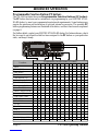
Programmable Function Button (PF button)
The VX-5500 includes the seven Programmable Function Buttons (PF button).
The PF button functions can be customized, via programming by your VERTEX STAN-
DARD dealer, to meet your communications/network requirements. Some features may
require the purchase and installation of optional internal accessories. The possible PF
button programming features are illustrated at the below, and their functions are explained
on page 8.
For further details, contact your VERTEX STANDARD dealer. For future reference, check
the box next to each function that has been assigned to the PF button on your particular
radio, and keep it handy.
Functions Programmable Function Button (PF button)
None
SCAN (SCN)
Dual Watch
Call/Reset
Talk-Around (TA)
Alpha Numeric (A/N)
DIMMER (DIM)
Emergency (EMG)
Horn Alert (HA)
Home Channel (HOM)
Intercom (IC)
Low Power (LOW)
GRP UP
GRP DWN
CH UP
CH DWN
AUX A
AUX B
AUX C
Public Address (PA)
Monitor (MON)
<1.5 sec >1.5 sec <1.5 sec >1.5 sec <1.5 sec >1.5 sec <1.5 sec >1.5 sec <1.5 sec >1.5 sec <1.5 sec >1.5 sec <1.5 sec >1.5 sec

Page 7
VX-5500 Operating Manual
ADVANCED OPERATION
<1.5 sec >1.5 sec <1.5 sec >1.5 sec <1.5 sec >1.5 sec <1.5 sec >1.5 sec <1.5 sec >1.5 sec <1.5 sec >1.5 sec <1.5 sec >1.5 sec
Functions Programmable Function Button (PF button)
RCL
Selectable Tone (ST)
SP*
Squelch Level (SQL)
Compander
Encryption** (OPT)
* requires RMK-4000 ** requires Encryption Unit
Channel Scan
The Scanning feature is used to monitor multiple signals programmed into the trans-
ceiver. While scanning, the transceiver will check each channel for the presence of a
signal, and will stop on a channel if a signal is present.
To activate scanning:
mPress the assigned PF button of the “Scan” momentarily to activate scanning.
mThe scanner will search the channels, looking for active ones; it will pause each
time it finds a channel on which someone is speaking.
To stop scanning
mPress the assigned PF button of the “Scan”.
mOperation will revert to the channel to which the CHANNEL selector knob is set.
Note:Your dealer may have programmed your radio to stay on one of the following
channels if you press the PTT switch during scanning pause:
rCurrent channel (“Talk Back”)
r“Last Busy” channel
r“Priority” channel
r“Home” channel
r“Scan Start” channel
Dual Watch
The Dual Watch feature is similar to the Scan feature, except that only two channels
are monitored:
rThe current operating channel; and
rThe “Priority” channel.
To activate Dual Watch:
mPress the assigned PF button of the “Dual Watch”.
mThe scanner will search the two channels; it will pause each time it finds a channel
on which someone is speaking.
To stop Dual Watch:
mPress the assigned PF button of the “Dual Watch”.
mOperation will revert to the channel to which the CHANNEL selector knob is set.

Page 8 VX-5500 Operating Manual
ARTS (Auto Range Transpond System)
This system is designed to inform you when you and another ARTS-equipped station are
within communication range.
During ARTS operation, your radio automatically transmits for about 1 second every 25
(or 55) seconds (the interval is programmed by Dealer) in an attempt to Shake hands with
the other station.
If you move out of range for more than one minutes, your radio senses that no signal has
been received, a ringing beeper will sound. If you subsequently move back into range, as
soon as the other station transmits, your beeper will sound.
The PF Button Function
The PF (Programmable Function) button can be programmed by the dealer to provide
two of the other functions described below.
To activate the primary Accessory function, press the PF button momentarily. To access
the secondary Accessory function (which may include the Alarm), press and hold the PF
button for 1.5 seconds or longer.
Call/Reset
When this feature is programmed and a selective call has been received, momen-
tarily press the assigned PF button of the “Call/Reset” to reset the flashing indicator
and mute the receiver, otherwise press the assigned PF button of the “Call/Reset” to
sent your radio’s identification code (ANI) to the dispatcher.
Talk-Around
The feature causes the assigned PF button of the “Talk-Around” to select simplex
operation on semi-duplex channels: the transmit frequency becomes the same as the
receive frequency (regardless of any programmed offset for the channel).
Note:This feature has no effect on simplex channels. After pressing the button,
“-TAKARD-” is displayed on the LCD.
Alpha Numeric
Press the assigned PF button of the “Alpha Numeric” to switch the display between
the Group/Channel number, and the Group/Channel name (alphanumeric). A tone
will sound each time you switch between numerical and alphanumerical display.
DIM
Press the assigned PF button of the “DIM” to adjust the brightness of the display and
key backright.
ADVANCED OPERATION

Page 9
VX-5500 Operating Manual
EMG (Emergency)
Press the assigned PF button of the “EMG” to initiate an emergency call (requires
ANI board). When an emergency call is made, not tone is emitted and the display
does not change. To end the emergency call, turn the transceiver power OFF.
HA (Horn Alert)
Press the assigned PF button of the “HA” to turn the Horn Alert function ON or
OFF. If you receive a call from the base station with 2Tone or DTMF signaling, horn
alert will activate.
When you turn Horn Alert ON, a tone will sound and “ ” appears on the display.
Home (Home Channel)
Press the assigned PF button of the “Home” to select the pre-programmed Home
Channel. Press it again to return to the previous channel. If used while scanning,
pressing this key a second time will change to the revert channel.
IC (Intercom)
This feature requires dual head configuration. Press the assigned PF button of the
“IC” to turn the intercom feature ON or OFF. While ON, you can press the PTT
switch to communicate to another control head operator without transmitting over
the air. When you press this key, a tone sounds and “ ” appears on the display. The
intercom can be used even while scanning and receiving a call
Low Power
Press the assigned PF button of the “Low Power” to set the radio's transmitter to the
“Low Power” mode.
Press this key again to return to “High Power” operation when in difficult terrain.
GRP UP/DWN
Press the assigned PF button of the “GRP UP” or “GRP DWN” to select a different
group of channels.
CH UP/DWN
Press the assigned PF button of the “CH UP” or “CH DWN” to select a different
channel within the current group.
AUX A/B/C
Press the assigned PF button of the “AUX A”, “AUX B”, or “AUX C” to turn the
output port (respectively).
PA (Public Address)
Press the assigned PF button of the “PA” to use the transceiver as a PA amplifier.
When you enable this function, a tone sounds and “ ” appears on the display.
The public address can be used even while scanning and receiving a call.
ADVANCED OPERATION

Page 10 VX-5500 Operating Manual
MONI (Monitor)
Press the assigned PF button of the “MONI” momentarily to cancel CTCSS and
DCS signaling squelch; the “MON” icon appears on the display. Press and hold this
key for 1/2 seconds to hear background noise (unmute the audio); the MON icon
blinks on the display.
RCL (Channel Recall)
During scan, you can press the assigned PF button of the “RCL” to select the last
called channel.
ST (Selectable Tone)
Press the assigned PF button of the “Selectable Tone”, then rotate the CHANNEL
selector knob to select a 2-Tone.
SP
Press the assigned PF button of the “SP” to switch “Front panel”, “Front panel &
Body” and “Body” speaker. When “Body” is selected, a tone sounds and the “ ”
icon appears on the display. You can use this function while scanning and receiving
a call. However, all audio will be emitted from the PA speaker.
SQL (Squelch Level)
You can manually adjust the squelch level using this function:
1. Press the assigned PF button of the “SQL”. A tone sounds and SQL appears on
the display with the current squelch level.
2. Rotate the CHANNEL selector knob to select the desired level.
3. Press the this key. A tone sounds and the display returns to the normal channel.
COMP (Compander)
Press the PF button assigned to the “COMP” function to turn the “Compander” IC
ON or OFF.
This IC contains two variable gain circuits configured for compressing and expand-
ing the dynamic range of the radio's transmitted and received audio signal.
When you enable this function, the signal-to-noise radio can be improved by reduc-
ing the transmitted audio dynamic range.
Encryption (Option)
When the Voice Scrambler feature is enabled, pressing the assigned PF button of the
“Encryption” toggles the Scrambler on and off.
ADVANCED OPERATION

Page 11
VX-5500 Operating Manual
OPTIONAL ACCESSORIES
MH-25B7A Microphone
MH-53C7A Heavy Duty Microphone
MH-53A7A Heavy Duty Microphone w/Noise Canceler
MH-53B7A Heavy Duty DTMF Microphone w/Noise Canceler
CE49 Programming Software
CT-70 Radio Programming Cable (Requires VPL-1)
CT-71 Radio to PC Programming Cable
CT-72 Radio to Radio Programming Cable
CT-81 Cable for RMK-4000 (6 m)
CT-82 Cable for RMK-4000 (2.5 m)
CT-83 Cable for RMK-4000 (0.6 m)
CNT-6000 Control Head
RF DECK RF Deck w/MMB-79 (for Dual Band Installations)
RMK-4000SH Remote Kit (for Single Transceiver)
RMK-4000DH Remote Kit (for Dual-Head Installations)
RMK-4000DB Remote Kit (for Dual Band Installations)
RMK-4000DBH Remote Kit (for Dual Band plus Dual Head Installations)
F2D-8 2-Tone Decode Unit (Requires FIF-7)
F5D-14 5-Tone ENC-DEC Unit (Requires FIF-7)
VTP-50 VX-Trunk Unit (Requires FIF-7)
FVP-25 Encryption/DTMF pager Unit (Requires FIF-7)
FP-1030 External 30A Power Supply
MLS-100 Mobile Loud speaker (12 W Peak Power)
MMB-79 Mobile Mounting Bracket
MMB-77 Locking Mobile Mounting Bracket
FIF-7 Inter face Board (for F2D-8, F5D-14, VTP-50, FVP-25)
CN-6 Inter face Board (for Accessories)


VX-3200 OPERATING MANUAL
This device complies with Part 15 of the FCC rules.
Operation is subject to the condition that this device does not cause
harmful interference.
Part 15.21: Changes or modifications to this device not expressly ap-
proved by Vertex Standard could void the user’s authorization to oper-
ate this device.

-
 1
1
-
 2
2
-
 3
3
-
 4
4
-
 5
5
-
 6
6
-
 7
7
-
 8
8
-
 9
9
-
 10
10
-
 11
11
-
 12
12
-
 13
13
-
 14
14
-
 15
15
-
 16
16


Vertex Standard 8x8 HDMI-HDBaseT Matrix Switcher Istruzioni per l'uso
- Tipo
- Istruzioni per l'uso
in altre lingue
Altri documenti
-
Motorola HT1250-LS+ Manuale utente
-
-
Kenwood TM-701A Manuale utente
-
Furuno FM4800 Manuale utente
-
Raymarine Ray 201 Manuale utente
-
-
-
Kenwood TM-331A Manuale utente
-