Genius Master Slave T Istruzioni per l'uso
- Tipo
- Istruzioni per l'uso

Master-T &
Slave-T

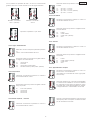
AVVERTENZE PER L’INSTALLATORE
OBBLIGHI GENERALI PER LA SICUREZZA
1) ATTENZIONE! È importante per la sicurezza delle persone seguire attentamente tutta l’istruzione.
Una errata installazione o un errato uso del prodotto può portare a gravi danni alle persone.
2) Leggere attentamente le istruzioni prima di iniziare l’installazione del prodotto.
3) I materiali dell’imballaggio (plastica, polistirolo, ecc.) non devono essere lasciati alla portata
dei bambini in quanto potenziali fonti di pericolo.
4) Conservare le istruzioni per riferimenti futuri.
5) Questo prodotto è stato progettato e costruito esclusivamente per l’utilizzo indicato in questa
documentazione. Qualsiasi altro utilizzo non espressamente indicato potrebbe pregiudicare
l’integrità del prodotto e/o rappresentare fonte di pericolo.
6) GENIUS declina qualsiasi responsabilità derivata dall’uso improprio o diverso da quello per cui
l’automatismo è destinato.
7) Non installare l’apparecchio in atmosfera esplosiva: la presenza di gas o fumi infiammabili
costituisce un grave pericolo per la sicurezza.
8) Gli elementi costruttivi meccanici devono essere in accordo con quanto stabilito dalle Norme
EN 12604 e EN 12605.
Per i Paesi extra-CEE, oltre ai riferimenti normativi nazionali, per ottenere un livello di sicurezza
adeguato, devono essere seguite le Norme sopra riportate.
9) GENIUS non è responsabile dell’inosservanza della Buona Tecnica nella costruzione delle
chiusure da motorizzare, nonché delle deformazioni che dovessero intervenire nell’utilizzo.
10) L’installazione deve essere effettuata nell’osservanza delle Norme EN 12453 e EN 12445. Il livello
di sicurezza dell’automazione deve essere C+D.
11) Prima di effettuare qualsiasi intervento sull’impianto, togliere l’alimentazione elettrica e scollegare
le batterie.
12) Prevedere sulla rete di alimentazione dell’automazione un interruttore onnipolare con distanza
d’apertura dei contatti uguale o superiore a 3 mm. È consigliabile l’uso di un magnetotermico
da 6A con interruzione onnipolare.
13) Verificare che a monte dell’impianto vi sia un interruttore differenziale con soglia da 0,03 A.
14) Verificare che l’impianto di terra sia realizzato a regola d’arte e collegarvi le parti metalliche
della chiusura.
15) L’automazione dispone di una sicurezza intrinseca antischiacciamento costituita da un control-
lo di coppia. E' comunque necessario verificarne la sogli di intervento secondo quanto
previsto dalle Norme indicate al punto 10.
16) I dispositivi di sicurezza (norma EN 12978) permettono di proteggere eventuali aree di pericolo
da Rischi meccanici di movimento, come ad Es. schiacciamento, convogliamento,
cesoiamento.
17) Per ogni impianto è consigliato l’utilizzo di almeno una segnalazione luminosa nonché di un
cartello di segnalazione fissato adeguatamente sulla struttura dell’infisso, oltre ai dispositivi citati
al punto “16”.
18) GENIUS declina ogni responsabilità ai fini della sicurezza e del buon funzionamento dell’auto-
mazione, in caso vengano utilizzati componenti dell’impianto non di produzione GENIUS.
19) Per la manutenzione utilizzare esclusivamente parti originali GENIUS.
20) Non eseguire alcuna modifica sui componenti facenti parte del sistema d’automazione.
21) L’installatore deve fornire tutte le informazioni relative al funzionamento manuale del sistema in
caso di emergenza e consegnare all’Utente utilizzatore dell’impianto il libretto d’avvertenze
allegato al prodotto.
22) Non permettere ai bambini o persone di sostare nelle vicinanze del prodotto durante il
funzionamento.
23) Tenere fuori dalla portata dei bambini radiocomandi o qualsiasi altro datore di impulso, per
evitare che l’automazione possa essere azionata involontariamente.
24) Il transito tra le ante deve avvenire solo a cancello completamente aperto.
25) L’Utente utilizzatore deve astenersi da qualsiasi tentativo di riparazione o d’intervento diretto e
rivolgersi solo a personale qualificato.
26) Non mettere in corto circuito i poli delle batterie e non tentare di ricaricarle con alimentatori
diversi dalle schede Master o Slave.
27) Non gettare le batterie esauste nei rifiuti ma smaltirle utilizzando gli appositi contenitori per
consentirne il riciclaggio. I costi di smaltimento sono già stati pagati dalla casa costruttrice.
28) Tutto quello che non è previsto espressamente in queste istruzioni non è permesso
IMPORTANT NOTICE FOR THE INSTALLER
GENERAL SAFETY REGULATIONS
1) ATTENTION! To ensure the safety of people, it is important that you read all the following
instructions. Incorrect installation or incorrect use of the product could cause serious harm to
people.
2) Carefully read the instructions before beginning to install the product.
3) Do not leave packing materials (plastic, polystyrene, etc.) within reach of children as such
materials are potential sources of danger.
4) Store these instructions for future reference.
5) This product was designed and built strictly for the use indicated in this documentation. Any other
use, not expressly indicated here, could compromise the good condition/operation of the
product and/or be a source of danger.
6) GENIUS declines all liability caused by improper use or use other than that for which the
automated system was intended.
7) Do not install the equipment in an explosive atmosphere: the presence of inflammable gas or
fumes is a serious danger to safety.
8) The mechanical parts must conform to the provisions of Standards EN 12604 and EN 12605.
For non-EU countries, to obtain an adequate level of safety, the Standards mentioned above
must be observed, in addition to national legal regulations.
9) GENIUS is not responsible for failure to observe Good Technique in the construction of the
closing elements to be motorised, or for any deformation that may occur during use.
10) The installation must conform to Standards EN 12453 and EN 12445. The safety level of the
automated system must be C+D.
11) Before attempting any job on the system, cut out electrical power and disconnect the
batteries.
12) The mains power supply of the automated system must be fitted with an all-pole switch with
contact opening distance of 3mm or greater. Use of a 6A thermal breaker with all-pole circuit
break is recommended.
13) Make sure that a differential switch with threshold of 0.03 A is fitted upstream of the system.
14) Make sure that the earthing system is perfectly constructed, and connect metal parts of the
means of the closure to it.
CONSIGNES POUR L'INSTALLATEUR
RÈGLES DE SÉCURITÉ
1) ATTENTION! Il est important, pour la sécurité des personnes, de suivre à la lettre toutes les
instructions. Une installation erronée ou un usage erroné du produit peut entraîner de graves
conséquences pour les personnes.
2) Lire attentivement les instructions avant d'installer le produit.
3) Les matériaux d'emballage (matière plastique, polystyrène, etc.) ne doivent pas être laissés
à la portée des enfants car ils constituent des sources potentielles de danger.
4) Conserver les instructions pour les références futures.
5) Ce produit a été conçu et construit exclusivement pour l'usage indiqué dans cette
documentation. Toute autre utilisation non expressément indiquée pourrait compromettre
l'intégrité du produit et/ou représenter une source de danger.
6) GENIUS décline toute responsabilité qui dériverait d'usage impropre ou différent de celui
auquel l'automatisme est destiné.
7) Ne pas installer l'appareil dans une atmosphère explosive: la présence de gaz ou de fumées
inflammables constitue un grave danger pour la sécurité.
8) Les composants mécaniques doivent répondre aux prescriptions des Normes EN 12604 et EN
12605.
Pour les Pays extra-CEE, l'obtention d'un niveau de sécurité approprié exige non seulement le
respect des normes nationales, mais également le respect des Normes susmentionnées.
9) GENIUS n'est pas responsable du non-respect de la Bonne Technique dans la construction des
fermetures à motoriser, ni des déformations qui pourraient intervenir lors de l'utilisation.
10) L'installation doit être effectuée conformément aux Normes EN 12453 et EN 12445. Le niveau de
sécurité de l'automatisme doit être C+D.
11) Couper l'alimentation électrique et déconnecter la batterie avant toute intervention sur
l'installation.
12) Prévoir, sur le secteur d'alimentation de l'automatisme, un interrupteur omnipolaire avec une
distance d'ouverture des contacts égale ou supérieure à 3 mm. On recommande d'utiliser un
magnétothermique de 6A avec interruption omnipolaire.
13) Vérifier qu'il y ait, en amont de l'installation, un interrupteur différentiel avec un seuil de 0,03 A.
14) Vérifier que la mise à terre est réalisée selon les règles de l'art et y connecter les pièces
métalliques de la fermeture.
15) L'automatisme dispose d'une sécurité intrinsèque anti-écrasement, formée d'un contrôle du
couple. Il est toutefois nécessaire d'en vérifier le seuil d'intervention suivant les prescriptions des
Normes indiquées au point 10.
16) Les dispositifs de sécurité (norme EN 12978) permettent de protéger des zones éventuellement
dangereuses contre les Risques mécaniques du mouvement, comme l'écrasement,
l'acheminement, le cisaillement.
17) On recommande que toute installation soit doté au moins d'une signalisation lumineuse, d'un
panneau de signalisation fixé, de manière appropriée, sur la structure de la fermeture, ainsi que
des dispositifs cités au point “16”.
18) GENIUS décline toute responsabilité quant à la sécurité et au bon fonctionnement de
l'automatisme si les composants utilisés dans l'installation n'appartiennent pas à la production
GENIUS.
19) Utiliser exclusivement, pour l'entretien, des pièces GENIUS originales.
20) Ne jamais modifier les composants faisant partie du système d'automatisme.
21) L'installateur doit fournir toutes les informations relatives au fonctionnement manuel du système
en cas d'urgence et remettre à l'Usager qui utilise l'installation les "Instructions pour l'Usager"
fournies avec le produit.
22) Interdire aux enfants ou aux tiers de stationner près du produit durant le fonctionnement.
23) Eloigner de la portée des enfants les radiocommandes ou tout autre générateur d'impulsions,
pour éviter tout actionnement involontaire de l'automatisme.
24) Le transit entre les vantaux ne doit avoir lieu que lorsque le portail est complètement ouvert.
25) L'Usager qui utilise l'installation doit éviter toute tentative de réparation ou d'intervention directe
et s'adresser uniquement à un personnel qualifié.
26) Ne pas mettre en court-circuit les pôles des batteries et ne pas tenter de les recharger avec
d'autres platines d'alimentation que les platines Maître ou Esclave.
27) Ne pas jeter les batteries épuisées à la poubelle, mais les éliminer dans les conteneurs
spécifiques pour le recyclage. Les coûts d'élimination des déchets ont déjà été payés par le
constructeur.
28) Tout ce qui n'est pas prévu expressément dans ces instructions est interdit.
15) The automated system is supplied with an intrinsic anti-crushing safety device consisting of a
torque control. Nevertheless, its tripping threshold must be checked as specified in the
Standards indicated at point 10.
16) The safety devices (EN 12978 standard) protect any danger areas against mechanical
movement Risks, such as crushing, dragging, and shearing.
17) Use of at least one indicator-light is recommended for every system, as well as a warning sign
adequately secured to the frame structure, in addition to the devices mentioned at point “16”.
18) GENIUS declines all liability as concerns safety and efficient operation of the automated
system, if system components not produced by GENIUS are used.
19) For maintenance, strictly use original parts by GENIUS.
20) Do not in any way modify the components of the automated system.
21) The installer shall supply all information concerning manual operation of the system in case of
an emergency, and shall hand over to the user the warnings handbook supplied with the
product.
22) Do not allow children or adults to stay near the product while it is operating.
23) Keep remote controls or other pulse generators away from children, to prevent the automated
system from being activated involuntarily.
24) Transit through the leaves is allowed only when the gate is fully open.
25) The user must not attempt any kind of repair or direct action whatever and contact qualified
personnel only.
26) Do not short-circuit the poles of the batteries and do not try to recharge the batteries with power
supply units other than Master or Slave cards.
27) Do not throw exhausted batteries into containers for other waste but dispose of them in the
appropriate containers to enable them to be recycled. Disposal costs have already been
paid for by the manufacturer.
28) Anything not expressly specified in these instructions is not permitted.

1
ITALIANO
cdV42airosseccaxamociraC Am051
odiparerottennocxamociraC Am05
otnemanoiznufidehcigoL
ossap"acitamotuA/acit
amotuA
/azzeruciS/"ossap
”ossapossap“acitamotuaimeS
arusuihc/arutrepa’dopmeT otnemidnerppaotuanI
asuapidop
meT .ces03,02,01,5elibammargorP
niatna’dodratiridopmeT
arusuihcearutrepa
-)s2hc,s2pa(-)s0hc,s0pa(
)s8hc,s2
pa(-)s4hc,s2pa(
àticoleV illevil4uselibanoizeleS
acitatsazrofenoizalogeR illevil4uselibanoizeleS
areittesr
omniissergnI
-atalocnivsatnanepO-nepO
ezzeruciS-.paniezzeruciS-potS
.hcni
areittesromnieticsU
-suB-erotoM-
erotaiggepmaL
enoizatnemilA-aipsadapmal
cdV21-cdV42irossecca
odiparerottennoC nip5oidaritneveciR
ilibammar
gorpinoiznuF
'didratir-asuapopmet-acigoL
-arusuihcearutrepaniatna
-otnemaiccaihcsitnaidazrof
irotarepoilg
edàticolev
areittesromnieticsU erotoM
areittesromniissergnI suB-enoizatnemilaoppurG
~Venoizatnemila'denoisneT zH06/05~)%01-%6+(032
ivitucesnocilciC 03
)1(
airettaballedaciraciridopmeT otiugeseolcicingorep'2~
)1(
erotinetnocenoizetorpidodarG 55PI
atibrossaaznetoP W081
erotomxametnerroC A51
etneibmaarutarepmeT C°55+÷C°02
-
enoizetorpidilibisuF A02-1°N
otnemaiccaihcsitnaenoiznuF etnerrocollortnoC-redocnE
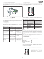
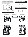
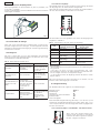
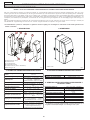
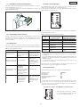
Fig.1
Fig.2
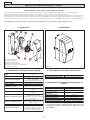
• quote in mm
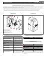
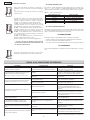
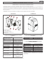
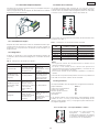
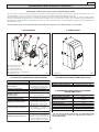
APPARECCHIATURA ELETTRONICA MASTER-T e SLAVE-T
Le presenti istruzioni sono valide per i seguenti modelli:
APPARECCHIATURE MASTER-T E SLAVE-T PER AUTOMAZIONI A BATTENTE
L’automazione è costituita da attuatori elettromeccanici irreversibili, alimentati a 12 Vdc tramite trasformatore toroidale e scheda
alimentazione; abbinati ognuno ad un'apparecchiatura elettronica.
L'apparecchiatura SLAVE-T (necessaria solo su cancelli a 2 ante) è comandata dall'apparecchiatura MASTER-T alla quale sono
collegati tutti gli accessori e i datori d'impulso. La scheda MASTER-T è programmabile e permette di impostare le logiche di funziona-
mento, i tempi di lavoro (in auto-apprendimento) e di pausa, la velocità delle ante e la sensibilità dell'antischiacciamento.
L'automazione è stata progettata e costruita per controllare l’accesso veicolare. Evitare qualsiasi altro diverso utilizzo.
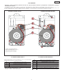
1. DESCRIZIONE 2. DIMENSIONI
3. CARATTERISTICHE TECNICHE SCHEDA MASTER-T 4. CARATTERISTICHE TECNICHE SCHEDA SLAVE-T
5. CARATTERISTICHE TECNICHE COMUNI SCHEDE
MASTER-T E SLAVE-T
(1)
La protezione termica software permette di eseguire 30 cicli
consecutivi. Il tempo di recupero è di 2 minuti per ogni ciclo
eseguito.
2
1
3
4
5
6
6
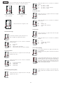
1) Scheda elettronica
2) Supporto scheda
3) cheda alimentatore
4) Trasformatore toroidale
5) Morsettiera (solo MASTER-T)
6) Contenitore IP 55

2
ITALIANO
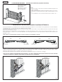
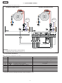
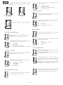
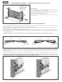
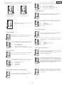
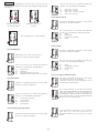
1) Operatore Master
2) Operatore Slave
3) Fotocellule
4) Pulsante a chiave
5) Ricevente radio
6) Lampeggiatore
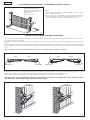
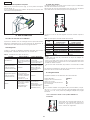
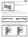
Fig.3
Fig.4
Fig.5
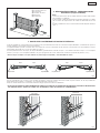
Scheda MASTER-T
Anta 2 Anta 1
Scheda SLAVE-T
Scheda MASTER-T
Anta 2Anta 1
Scheda SLAVE-T
N°4 Fori Ø5
N°4 Fori Ø5
6. DESCRIZIONE IMPIANTO - Predisposizioni elettriche (impianto standard)
Note:
1) Per la messa in opera dei cavi elettrici utilizzare adeguati tubi
rigidi e/o flessibili.
2) Per evitare qualsiasi interferenza separare sempre i cavi di col-
legamento a bassa tensione da quello di alimentazione a 230
V~.
3) Per l'installazione dei contenitori delle schede vedere cap. 7.
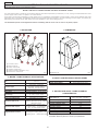
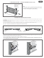
7. MONTAGGIO CONTENITORE APPARECCHIATURA ELETTRONICA
Prima di procedere con l'installazione dei contenitori delle apparecchiature occorre definire dove posizionare la scheda MASTER-T,
considerando che ad essa andranno poi collegati tutti gli accessori.
La scheda MASTER-T può essere montata sia alla destra sia alla sinistra del cancello, occorre definire solamente a quale anta essa sarà
associata come indicato in Fig. 4.
Nelle applicazioni a doppia anta la scheda MASTER-T comanda generalmente l'anta 1. Nel caso si voglia comandare l'anta 1 con
la scheda SLAVE-T e l'anta 2 con la scheda MASTER-T occorre programmare in modo appropriato il sistema (fare riferimento al
paragrafo 12.4.1).
Nota: L'anta 1 è sempre quella che parte per prima in apertura ed è ritardata in chiusura.
Montare i contenitori delle apparecchiature MASTER-T (alla quale andranno collegati tutti gli accessori e datori di impulso) e SLAVE-
T nelle vicinanze degli operatori con 4 tasselli e relative viti di fissaggio. Far arrivare i cavi elettrici nella parte inferiore della cassetta
utilizzando adeguati tubi rigidi e/o flessibili ed appositi raccordi (Fig. 5).
Avere premura di lasciare i cavi all'interno del contenitore abbastanza lunghi per effettuare i cablaggi.
NOTA: PER UN CORRETTO FUNZIONAMENTO DELL'IMPIANTO I CAVI DEGLI OPERATORI NON DEVONO ESSERE PER ALCUNA RAGIONE
ALLUNGATI O MODIFICATI. TENERNE CONTO PRIMA DEL MONTAGGIO DEI CONTENITORI.

3
ITALIANO
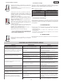
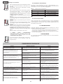
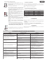
1F A02F-erotomeairettabelibisuF
2J subotnemagellocareittesroM
3J erotomotnemagellocareittesroM
4J enoizatnem
ilaoppurgotnemagellocerottennoC
5J zH05~V032enoisneTotnemagellocerottennoC
1P "enoiznuF"enoizammargorpidetnasluP
2P "erolaV"enoizammargorpidetnasluP
1F A02F-erotomeairettabelibisuF
1
J irosseccAareittesroM
2J otazzilitunoN
3J erotomotnemagellocareittesroM
4J enoizatnemilaoppurgotnemagelloce
rottennoC
5J zH05-~032enoisneTotnemagellocerottennoC
6J itnevecirreperottennoC
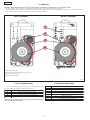
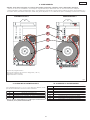
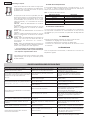
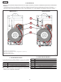
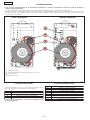
Fig.6
APPARECCHIATURA SLAVE-T APPARECCHIATURA MASTER-T
1) LED di programmazione
2) Led di diagnostica ( LED P )
3) Scheda alimentazione
4) Trasformatore toroidale
8. AVVERTENZE
Attenzione : Prima di effettuare qualsiasi intervento sull' apparecchiatura elettronica (collegamenti, manutenzione) scollegare
l'alimentazione elettrica.
• Prevedere a monte dell' impianto un interruttore magnetotermico differenziale con adeguata soglia di intervento.
• Separare sempre il cavo di alimentazione 230V~ da quelli di comando e di sicurezza (pulsanti, ricevente, fotocellule, ecc.). Per
evitare qualsiasi disturbo elettrico utilizzare guaine separate o cavo schermato (con schermo collegato a massa).
9. LAYOUT SCHEDA SLAVE-T
Sulla scheda SLAVE-T non sono presenti J1, J6, P1, P2 e LED mentre
gli altri elementi hanno le seguenti funzioni.
Nota: il Gruppo Alimentazione è costituito dal trasformatore
toroidale e dalla scheda alimentatore.
10. LAYOUT SCHEDA MASTER-T
1
2
3
4
J6
P2
P1
J1
J5
J2
F1
J4
J3
J5
J2
J4
F1
J3

4
ITALIANO
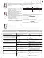
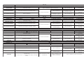
ottesroMenoizircseD otagellocoirosseccA
1ANEPO )2e1etnaarutrepaodnamoc( )evaihcaetnaslup.sE(.A.Nottatnocnoc
ovitisopsiD
2BNEPO )1atnaarutrepaodnamoc( )evaihcaetnaslup.sE(.A.NottatnocnocovitisopsiD
3POTS )ollecnacocco
lbodnamoc( .C.NottatnocnocovitisopsiD
)1(
4POWSF )arutrepaniezzerucisottatnoC( elullecotoF
)1(
5LCWSF )arusuihcniezzerucisottatnoC( elullecotoF
)1(
6SUB )T-EVALS-T-RETSAMarfotnemagelloC( /
8-7+ )V42enoizatnemilaovitisop( Am051idirosseccaXAMelatototnemibros
sA
11-9.L.W )aipsadapmalenoizatnemilA( W5,0-V21adadapmaL
11-01PMAL )erotaiggepmalenoizatnemilA( V21etnaiggepm
aL
51÷21- )cdV42enoizatnemilaovitagen( /
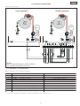
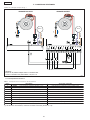
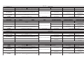
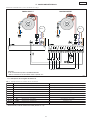
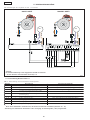
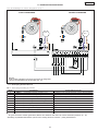
Fig.7
APPARECCHIATURA SLAVE-T APPARECCHIATURA MASTER-T
Attenzione:
Nel collegamento BUS rispettare la polarità indicata.
* Per il collegamento delle fotocellule vedi par. 11.2
*
MARRONE
BLU
Motore
MARRONE
BLU
Motore
11. COLLEGAMENTI ELETTRICI
Eseguire i cablaggi come indicato in Fig. 7.
11.1 Descrizione morsettiera J1
Tab. 1 - Descrizione collegamento accessori
(1)
In assenza di accessori collegare il morsetto a massa (morsetti 12 ÷ 15).

5
ITALIANO
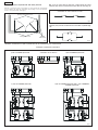
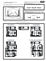
Fig.8
Fig.9
Fig.10
Fig.11
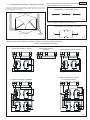
Sicurezze in apertura/chiusura
Sicurezze in chiusura
Sicurezze in
apertura
Collegamento di 2 contatti N.C. in serie
Collegamento di 2 contatti N.A. in parallelo
1 coppia di fotocellule in chiusura
collegamento di nessun
dispositivo
1 coppia di fotocellule in apertura
2 coppie di fotocellule in CHIUSURA
1 coppia di fotocellule in chiusura
e 1 in apertura/chiusura
11.2 Collegamento fotocellule e dispositivi di sicurezza
Prima di collegare le fotocellule (o altri dispositivi) è opportuno
sceglierne il tipo di funzionamento in base alla zona di movimento
da proteggere (vedi Fig. 8).
N.B.: se due dispositivi con contatto N.C. hanno la stessa funzione
vanno collegati in serie tra di loro (Fig. 9).
N.B.: se due dispositivi con contatto N.A. hanno la stessa funzione
vanno collegati in parallelo tra di loro (Fig. 10).
Attenzione: alla scheda elettronica si possono collegare al massimo 2 coppie di fotocellule
Esempi di collegamenti di fotocellule

6
ITALIANO
DELotatST-RETSAMadehcST-EVALSadehcS
ossifoseccA
azneserpalacidnI
eteridenoisnetalled
atnorpadehcse
.osu'lla
a
zneserpalacidnI
aleSUBled
nocenoizazzinorcnis
.T-RETSAMal
otneletnaiggepmaL
ingoenoisnecca(
)odnoces
.etnese
rpnoN
azneserpalacidnI
,eteridenoisnetalled
ènonadehcsalam
SUB(atazzinorcnis
)osottefid
etnaiggepmaL
enoisne
cca(ecolev
).cesm052ingo
enoizavitta'lacidnI
enoizetorpalled
erroccO.acimret
2onemlaerednetta
retoprepituni
m
.olcicnueriugese
.etneserpnoN
otnepS
aznacnamalacidnI
.eteridenoisnetalled
esafatseuqetnaruD
nonenoizamotu
a'l
.anoiznuf
aznacnamalacidnI
eteridenoisnetalled
alledaznessa'le
nocenoizazzinorcnis
SUB(T-RETSAMal
.)osottefid
deL
oseccA
)osuihcottatnoc(
otnepS
)otrepaottatnoc(
AnepO=AovittaodnamoC ovittaniodnamoC
BnepO=BovittaodnamoC o
vittaniodnamoC
potS=C ovittaniodnamoC ovittaodnamoC
powsF=D etangepmisidezzeruciS etangepmiezzeruciS
lcwsF=E
etangepmisidezzeruciS etangepmiezzeruciS
T-EVALS=1 avittaeetneserpT-EVALS avittanioetnessaT-EVALS
Fig.12
P1
P2
E
P1
P2
E
E
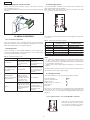
11.3 Collegamento schede riceventi
Inserire nel connettore a pettine J5 (Fig. 6) la scheda ricevente
come indicato in Fig. 12.
Per la programmazione della scheda ricevente riferirsi alle singole
istruzioni.
12. MESSA IN FUNZIONE
12.1 Accensione impianto
Dopo aver eseguito tutti i cablaggi descritti precedentemente
alimentare l'impianto per poter eseguire la diagnostica, la verifica
dello stati degli ingressi e la programmazione.
12.2 Diagnostica
Il led "P" (vedi Fig. 6), che è visibile dall'esterno del contenitore, ha
la funzione di diagnostica. Gli stati del led sono 3 che si differenzia-
no fra la scheda MASTER-T e SLAVE-T:
Tab. 2 - Descrizione stato led P
12.3 Stato degli ingressi
La scheda MASTER-T è dotata di una funzione per la verifica dello
stato degli ingressi sulla morsettiera.
Nello stato di tutti i leds spenti (sia quelli con le lettere che quelli
con i numeri) premere il pulsante P2.
L'accensione dei Leds segnala lo stato degli ingressi come riporta-
to in Tab. 3.
Tab. 3 - Descrizione leds stato ingressi
Note:
• In neretto le condizioni dei leds con il cancello chiuso a riposo.
• Il led 1 sarà attivo solamente quando è presente la
comunicazione BUS tra scheda MASTER-T e SLAVE-T negli impianti
con cancelli a doppia anta.
• Nella funzione stato degli ingressi il pulsante P1 comanda un
OPEN A.
Al termine delle verifiche premere nuovamente il pulsante P2 per
uscire dalla funzione stato degli ingressi.
12.4 Programmazione
La scheda MASTER-T ha le seguenti impostazioni di base:
Scheda MASTER-T ANTA 1
Logica funzionamento: A4
Tempi pausa: B1
Ritardo apertura/chiusura: C3
Forza statica: D3
Velocità: E2
Nel caso si voglia eseguire una programmazione personalizzata
(vedi par. da 12.4.1 a 12.4.6) e per eseguire l'apprendimento tem-
pi (vedi par. 12.4.7 e 12.4.8) seguire i passaggi indicati nelle pagine
seguenti.
12.4.1 Gestione anta 1 con scheda MASTER-T o SLAVE-T
Nello stato con tutti i leds spenti pre-
mendo e tenendo premuto il pulsan-
te P1, premere il pulsante P2; il Led A
si accende a luce lampeggiante.

7
ITALIANO
P1
P2
E
P1
P2
E
P1
P2
E
P1
P2
E
P1
P2
E
P1
P2
E
P1
P2
E
P1
P2
E
P1
P2
E
P1
P2
E
P1
P2
E
P1
P2
E
P1
P2
E
P1
P2
E
P1
P2
E
P1
P2
E
Con il pulsante P2 spostarsi dal Led 1 al Led 2 in funzione della
gestione anta che si vuole ottenere come di seguito descritto.
MASTER-T comanda l'
anta 1 (Default).
MASTER-T comanda l'
anta 2
Ripremere il pulsante P1 per uscire.
12.4.2 Logica Funzionamento
Nello stato di tutti i Leds spenti premere il pulsante
P1.
Il led A si accenderà assieme al led 4.
Premendo il tasto P2 si potranno scegliere 4 diver-
se logiche di funzionamento.
A1 automatica
A2 sicurezza
A3 automatica passo-passo
A4 semiautomatica passo-passo (default)
12.4.3 Tempi Pausa
Premendo nuovamente il pulsante P1 il led B si
accenderà assieme al led 1.
Premendo il tasto P2 si potranno scegliere 4 diversi
tempi di pausa.
B1 5 secondi (default)
B2 10 secondi
B3 20 secondi
B4 30 secondi
12.4.4 Ritardo Apertura / Chiusura
Premendo nuovamente il pulsante P1 il led C si
accenderà assieme al led 3.
Premendo il tasto P2 si potranno scegliere 4 diver-
si ritardi.
C1 ap 0 sec / ch 0 sec
C2 ap 2 sec / ch 2 sec
C3 ap 2 sec / ch 4 sec (default)
C4 ap 2 sec / ch 8 sec
12.4.5 Forza Statica
Premendo nuovamente il pulsante P1 il led D si
accenderà assieme al led 3.
Premendo il tasto P2 si potranno scegliere 4 diver-
se forze statiche.
D1 bassa
D2 medio bassa
D3 medio alta (default)
D4 alta
12.4.6 Velocità
Premendo nuovamente il pulsante P1 il led E si
accenderà assieme al led 2.
Premendo il tasto P2 si potranno scegliere 4 diver-
se velocità.
E1 bassa
E2 medio bassa (default)
E3 medio alta
E4 alta
12.4.7 Apprendimento semplice
Premendo nuovamente il pulsante P1 tutti e 5 i
led da A a E si accenderanno.
(Accertarsi che il cancello sia chiuso e gli opera-
tori bloccati)
Premendo il tasto P2 per 1 secondo l'anta MASTER-
T e l'anta SLAVE-T inizieranno a muoversi assieme
fino alla battuta meccanica di apertura. Duran-
te questa fase i 5 leds lampeggieranno. Termina-
to l'apprendimento i 5 leds restano accesi fissi.
Premere nuovamente il pulsante P1 per uscire (tutti
i leds spenti). Dare un impulso col radiocomando
per far richiudere il cancello.

8
ITALIANO
P1
P2
E
P1
P2
E
P1
P2
E
aipsadapmalotatSollecnacotatS
atnepSosuihC
aseccAasuapniotrepA-otrepA
etnaiggepmaLarusuihcnI
aseccAarutrepanI
a
seccAotaccolB
12.4.8 Apprendimento completo
Dopo aver impostato la velocità premendo il
pulsante P1 tutti e 5 i led da A a E si accenderan-
no.
(Accertarsi che il cancello sia chiuso e gli opera-
tori bloccati)
Premendo il tasto P2 per più di 3 secondi l'anta 1
inizierà a muoversi. Con successivi impulsi di P2
(oppure tramite pulsante a chiave o radioco-
mando) si comandano le seguenti funzioni:
1° imp. - inizio rallentamento in apertura anta 1.
Lasciare arrivare anta 1 in battuta e una volta
ferma inizia il movimento in apertura di anta 2.
(1)
2° imp. - inizio rallentamento in apertura anta 2.
Lasciare arrivare anta 2 in battuta e una volta
ferma inizia il movimento in chiusura di anta 2.
(1)
3° imp. - inizio rallentamento in chiusura anta 2 e
una volta arrivata in battuta inizia il movimento
in chiusura di anta 1.
4° imp. - inizio rallentamento in chiusura anta 1 e
lasciare arrivare in battuta anta 1.
Durante questa fase i 5 leds lampeggieranno.
(1)
se non si dispone di battute meccaniche di
apertura dare l'arresto nel punto desiderato con
un ulteriore impulso di P2
Premere nuovamente il pulsante P1 per uscire
terminato l'apprendimento (tutti i leds spenti).
12.5 Stato lampada spia
Nel caso si voglia utilizzare una lampada spia da 12V-0,5W (mor-
setto 9 - 11 di J1, vedi Fig. 7), nella tabella seguente sono riportati
gli stati della lampada in funzione della posizione del cancello.
Tab. 4 - Stati lampada spia
12.6 Prova dell'automazione
Terminata la programmazione, procedere alla verifica funzionale
accurata dell'automazione e di tutti gli accessori ad essa colle-
gati, in particolare dei dispositivi di sicurezza.
13. MANUTENZIONE
Effettuare almeno semestralmente le seguenti operazioni:
• Verifica della corretta regolazione dell'antischiacciamento.
• Controllo efficienza del sistema di sblocco.
• Controllo efficienza dei dispositivi di sicurezza e degli accessori.
14. RIPARAZIONI
Per eventuali riparazioni, rivolgersi ai Centri di Riparazione autoriz-
zati.
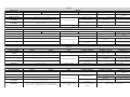
ailamonA esuaCilibissoP enoizuloS
adehcsPdeLataccolbenoizamotuA
.otnepsT-EVALSeT-RETSAM
allusaiseteridenoisnetidaznacnaM
.T-EVALS
adehcsallusaisT-RETSAMadehcs
aléhcnifotaccolbàrramirollecnaclI
.anrotirnoneteridenoisnet
nocevoumisnoN.a
taccolbenoizamotuA
oodnamocoidar(odnamocnussen
.oseccaèPdelliam)evaihcaerotteles
non)5e4(WSFe)3(POTSidit
tesroM
.itagelloc
ellusotatropiremociggalbacierallortnoC
enoisneccaatterrocaleracifireveinoizurtsi
.isser
gniilgedotatsollenE,D,Csdelied
.ittorilibisuF
ieriutitsosetnemlautnevedeerallortnoC
.)A02F(ilibisuf
adehc
sallaataicossaatna'lolosevoumiS
.evoumisnonT-EVALSalleuqeT-RETSAM
PdeL(attorretniSUBidenoissennoC
)otnel
etnaiggepmal
SUBotnemagellocledàtirgetni'leracifireV
.)7.giFidev(edehcseudelarf
adehcsallaeteridenoisnet
idaznacnaM
)otnepsPdeL(.T-EVALS
alledotnemagellocledàtirgetni'leracifireV
.)7.giFidev(eteridenoisnet
noco
losevoumiS.ataccolbenoizamotuA
.evaihcaodnamoc
.otsaugodnamocoidaR
alodnamocoidarortlanunoceracifireV
de,
otnaipmi'lledàtilanoiznufatterroc
odnamocoidarlieriutitsosetnemlautneve
.osottefid
.atsaugetneveciradehc
S
ataccolberesseatlusirenoizamotua'leS
liaisnonehcotatreccarevaopodehcna
eriutitsos,otsaugeressedaodnamo
coidar
.etneveciradehcsal
o/eitnematnupmiinartsahenoizamotua'L
.aznetrapallaipparts
asrocenifliotnuiggara
herotomlI
.ocinaccem
eroiretsopeeroiretnaihccattailgerametsiS
.ehcificepsademoc
earvonamorolalledoizini'l
laetnaeL
.etnemasotsivonallicsootomlietnarud
laataugedanonirotomiedàticoleV
.ollecnac
,irotomiedàticoleva
loilgemlaeralogeR
adehcsalledenoizammargorpniodnartne
.T-RETSAM
etuttabelegnuiggarollecnaclI
lietrevnidea
neipàticolevaehcinaccem
.otom
arutrepa/arusuihcniitnematnellaR
.itneiciffusni
anuodnecafitnematnellariera
gnullA
atelpmocenoizammargorp
.enoizamotua'lled
etrevniotnemivomlietnarudenoizamotua'L
.enoigaraznesotoml
i
olocatsonocortnocni(assabopportazroF
.)oizittif
ivnonetnaelledosrocreplenehceracifireV
ossennocsotlafsa
oissasilauq,ilocatsoonais
.irotomiedacitatsazrofaleratnemuae
erotomledotnemivomledaruttelatarrE
ledenoiz
atnemilaidovacliehcerallortnoC
.otacifidomootagnullaotatsaisnonerotom
GUIDA ALLA RISOLUZIONE DEI PROBLEMI

9
ITALIANO
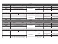
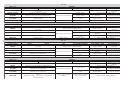
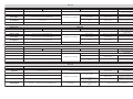
a/7.baT
"1A"ACIGOL ISLUPMI
OLLECNACOTATSA-NEPOBNEPOPOTSARUTREPAEZZERUCISARUSUIHCEZZERUCISHC/PAEZZERUCIS
OSUIHC a
suapidopmetliopodeduihciree/atna'lerpA )otibiniNEPO(otteffenusseNotteffenusseN
nepO(otteffenusseN
)otibin
i
ASUAPniOTREPA asuapopmetliaciraciR
otnemanoiznufliaccolB
otteffenusseNasuapopmetliaciraciR
ARUSUIHCNI etne
mataidemmie/atna'lerpaiR otteffenusseN
nietnemataidemmietrevnI
arutrepa
ongepmisidlaeaccolB
arutrepanietre
vni
ARUTREPANI otteffenusseN
nietnemataidemmietrevnI
arusuihc
otteffenusseN
ongepmisidlaeaccolB
erirpadaauni
tnoc
OTACCOLB e/atna'leduihCotteffenusseNotteffenusseN)otibininepO(otteffenusseN
b/7.baT
"2A"ACIGOL ISLUPMI
OLLECNACOTATSA-NEPOBNEPOPOTSARUTREPAEZZERUCISARUSUIHCEZZERUCISHC/PAEZZERUCIS
OSUIHC a
suapidopmetliopodeduihciree/atna'lerpA )otibiniNEPO(otteffenusseNotteffenusseN
nepO(otteffenusseN
)otibin
i
ASUAPniOTREPA etnemataidemmie/atna'leduihciR
otnemanoiznufliaccolB
otteffenusseN ongepmisidla)otibiniNEP
O("5opodeduihC
ARUSUIHCNI etnemataidemmie/atna'lerpaiR otteffenusseN
etnemataidemmietrevnI
arutrepani
ongep
misidlaeaccolB
arutrepanietrevni
ARUTREPANI etnemataidemmie/atna'leduihciR
nietnemataidemmietrevnI
arusuih
c
otteffenusseN
ongepmisidlaeaccolB
erirpadaaunitnoc
OTACCOLB e/atna'leduihCotteffenusseNotteffenusseN)otibin
inepO(otteffenusseN
c/7.baT
"3A"ACIGOL ISLUPMI
OLLECNACOTATSA-NEPOBNEPOPOTSARUTREPAEZZERUCISARUSUIHCEZZERUCISHC/PAEZZERUCIS
OSUIHC a
suapopmetliopodeduihciree/atna'lerpA )otibiniNEPO(otteffenusseNotteffenusseN
otteffenusseN
)otibininepO(
A
SUAPniOTREPA otnemanoiznufliaccolB
otnemanoiznufliaccolB
otteffenusseNasuapopmetliaciraciR
ARUSUIHCNI etnem
ataidemmie/atna'lerpaiR otteffenusseN
nietnemataidemmietrevnI
arutrepa
ongepmisidlaeaccolB
arutrepanietrevni
ARUTREPANI otnemanoiznufliaccolB
nietnemataidemmietrevnI
arusuihc
otteffenusseN
ongepmisidlaeaccolB
erirp
adaaunitnoc
OTACCOLB e/atna'leduihCotteffenusseNotteffenusseN)otibiniNEPO(otteffenusseN
d/7.baT
"4A"ACIGOL ISLUPMI
OLLECNACOTATSA-NEPOBNEPOPOTSARUTREPAEZZERUCISARUSUIHCEZZERUCISHC/PAEZZERUCIS
OSUIHC e
/atna'lerpA )otibiniNEPO(otteffenusseNotteffenusseN
NEPO(otteffenusseN
)otibini
OTREPA etnemataidemmie/atna
'leduihciR
otnemanoiznufliaccolB
otteffenusseN
)otibiniNEPO(otteffenusseN
ARUSUIHCNI otnemanoiznufliaccolB
nietnemataidemmietrevnI
arutrepa
ongepmisidlaeaccolB
arutrepanietrevni
ARUTREPANI otnemanoiznufliaccolB
nie
tnemataidemmietrevnI
arusuihc
otteffenusseN
ongepmisidlaeaccolB
erirpadaaunitnoc
OTACCOLB
osrevniosnesnioto
mliednerpiR:NEPOopoD
etnemataidemmie/atna'leduihciR:POTSopoD
NEPO(otteffenusseN
)otibini
otteffenusseN
ecs
ibini,erirpaevedes(
)NEPO
)otibininepO(otteffenusseN

10
ENGLISH
42tadaol.xamseirosseccA
cdV
Am051
daolxamrotcennocdipaR Am05
scigolnoitcnuF
"deppetS"/citamotuA
/ecivedytefa
S/citamotuA
citamotua-imes”deppetS“
emitgnisolc/gninepO gninrael-flesyB
emitesuaP .ces03,02,01,5:elbammarg
orP
gnineponehwemityaledfaeL
gnisolcdna
po(-)s2lc,s2po(-)s0lc,s0po(
)s8lc,s2po(-)s4lc,s2
deepS slevel4noelb
atceleS
tnemtsujdaecrofcitatS slevel4noelbatceleS
stupnidraoblanimreT
potS-faeldesaelernepO-nepO
ytefaS-.g
npotasecivedytefaS-
.gnslctasecived
stuptuodraoblanimreT
-suB-rotoM-pmalgnihsalF
42seirosseccA-thgil-rota
cidni
ylppusrewopcdV21-cdV
rotcennocdipaR reviecernip-5rofrotcennoC
snoitcnufelbammargorP
fael-emitesuap-c
igoL
-itna-yaledgnisolcdnagninepo
deepssrotarepo-ecrofgnihsurc
stuptuodraoblanimreT rotoM
stupnidraoblanimreT suB-tinUylppuSrewoP
~VylppusrewoP zH06/05~)%01-%6+(032
selcycevitucesnoC 03
)1(
emitegrahceryrettaB elcycdetelpmochcaerof'2~
)1(
ssalcnoitcetorperusolcnE 55PI
rewopdebrosbA W081
tnerrucxamrotoM A51
erutarepmettneibmagnitarepO C°55+÷C°02-
sesufnoitcetorP A02-1°N
noitcnufgnihsurc-itnA lortnoctnerruC-redocnE
Fig.1
Fig.2
2
1
3
4
5
6
6
MASTER-T AND SLAVE -T CONTROL BOARDS
These instructions apply to the following model:
MASTER-T AND SLAVE-T CONTROL BOARDS FOR SWING AUTOMATED SYSTEMS
The automated system consists of non-reversing electro-mechanical operators, powered by 12 Vdc, through toroidal transformer and
power supply board; each coupled to a control board.
The SLAVE-T control board (required on 2-leaf gates only) is controlled by the MASTER-T control board to which all accessories and pulse
generators are connected. The MASTER-T board can be programmed and is used to set the following: function logics, work times (by
self-learning) and pause times, leaf speed, and the sensitivity of the anti-crushing device.
The automated system was designed and built for controlling vehicle access. Do not use for any other purpose.
1. DESCRIPTION 2. DIMENSIONS
3. MASTER-T CARD TECHNICAL SPECIFICATIONS
4. SLAVE-T CARD TECHNICAL SPECIFICATIONS
5. MASTER-T AND SLAVE-T CARDS COMMON
CHARACTERISTICS
(1)
30 consecutive cycles can be performed with software thermal
protection. Recovery time is 2' each cycle performed.
• Dimensions in mm
1) Control board
2) Board support
3) Power unit board
4) Toroidal transformer
5) Terminal board (MASTER-T only)
6) Enclosure in class IP 55

11
ENGLISH
Fig.3
Fig.4
Fig.5
6. DESCRIPTION OF SYSTEM - ELECTRICAL EQUIPMENT (standard system)
Notes:
1) To lay electric cables, use adequate rigid and/or flexible tubes.
2) To avoid any kind of interference always separate low voltage
connection cables from 230V~ power cables.
3) See chpt. 7 for installation of boards enclosures.
7. INSTALLING THE CONTROL BOARD ENCLOSURE
The MASTER-T board positioning has to be decided before installing the control board enclosures since all accessories will be connected
to this board.
The MASTER-T board can be fitted either on the right or on the left side of the gate. You only have to decide to which leaf it will be
associated as shown in Fig. 4.
In double-leaf applications, the MASTER-T board always commands leaf 1. If you wish to command leaf 1 with the SLAVE-T board, and
leaf 2 with the MASTER-T board, you have to program the system in the appropriate way. (refer to chapter 12.4.1).
NB.: Leaf 1 is always the leaf that starts first on opening and is delayed on closing.
Install the enclosures of the MASTER-T control board (to which all accessories and pulse generators will be connected) and the SLAVE-
T units near the operators using 4 expansion bolts and their fixing screws. Route the electric cables to the bottom of the box using
adequate rigid and/or flexible tubes and proper joints (Fig. 5).
Leave the cables inside the enclosure lengthy enough to enable you to wire up.
NOTE: TO ENSURE CORRECT OPERATION OF THE SYSTEM, DO NOT, FOR ANY REASON, EXTEND OR MODIFY THE OPERATOR CABLES. BEAR
THIS IN MIND BEFORE INSTALLING THE ENCLOSURES.
4 holes Ø 5
4 holes Ø 5
MASTER-T board
Leaf 2 Leaf 1
SLAVE-T board MASTER-T board
Leaf 2Leaf 1
SLAVE-T board
1) MASTER-T Operator
2) SLAVE-T Operator
3) Photocells
4) Keyswitch
5) Receiver
6) Flashing light

12
ENGLISH
1F A02FesufrotomdnayrettaB
2J draoblanimretnoitcennocsuB
3J draoblanimretnoitcennocrotoM
4J tinUylppuSrewoPr
ofrotcennoC
5J rewoPzH05-~V032rofrotcennoC
1P "noitcnuF":nottub-hsupgnimmargorP
2P "eulaV":nottub-hsupgnimmargorP
1F A02FesufrotomdnayrettaB
1J draobla
nimretseirosseccA
2J desutoN
3J draoblanimretnoitcennocrotoM
4J rotcennocyrettaB
5J rewoPzH05-caV032rofrotcen
noC
6J reviecernip-5rofrotcennoC
1
2
3
4
J6
P2
P1
J1
J5
J2
F1
J4
J3
J5
J2
J4
F1
J3
Fig.6
8. WARNINGS
Attention: Before attempting any job on the control board (connections, maintenance), cut out electric power.
• Install, upstream of the system, a differential thermal breaker with adequate tripping threshold.
• Always separate 230V~ power cable from control and safety cables (push-buttons, receiver, photocells, etc.). To avoid any electric
noise, use separate sheaths or a shielded cable (with earthed shield).
9. SLAVE-T BOARD LAYOUT
J1, J6, P1, P2 and LED are not present on the SLAVE-T board, and
the other elements have the following functions.
Note: the Power Supply Unit consists of the toroidal transformer
and the power supply board.
10. MASTER-T BOARD LAYOUT
MASTER-T EQUIPMENT
SLAVE-T EQUIPMENT
1) Programming LED
2) Voltage ON and diagnostics LED( LED P )
3) Power supply board
4) Toroidal transformer

13
ENGLISH
lanimreTnoitpircseD yrosseccadetcennoC
1ANEPO )2dna1sevaelrofdnammocgninepo( )nottub-hsupdetarepoyek.g.e(tc
atnocANhtiweciveD
2BNEPO )1faelrofdnammocgninepo( )nottub-hsupdetarepoyek.g.e(tcatnocANhtiweciveD
3POTS )dna
mmockcoletag( .tcatnocCNhtiweciveD
)1(
4POWSF )tcatnocsecivedytefasgninepO( sllecotohP
)1(
5LCWSF )tcatnocsecivedytefasgnisolC( sllecotohP
)1(
6SUB )noitcennocT-EVALS-T-RETSAM( /
8-7+ )ylppusrewopV42rofevitisop( Am051fonoitprosbalatotXAMseirosseccA
11-
9.L.W )thgilrotacidniotylppusrewoP( pmalW5.0-V21
11-01PMAL )pmalgnihsalfotylppusrewoP( pmalgnihsalfV21
51÷21- )
ylppusrewopcdV42rofevitagen( /
Fig.7
*
11. ELECTRICAL CONNECTIONS
Wire up as shown in Fig. 7
11.1 Description of J1 terminal board
Tab. 1 - Description of accessories connection
(1)
If you are not using any accessories, connect the terminal to earth (terminals 12 - 15).
Attention:
observe the indicated polarity on the BUS connection.
* For connection of photocells, see par. 11.2
Motor
BROWN
BLUE
Motor
BROWN
BLUE
MASTER-T EQUIPMENTSLAVE-T EQUIPMENT

14
ENGLISH
Fig.8
Fig.9
Fig.10
Fig.11
11.2 Connection of photocells and safety devices
Before connecting the photocells (or other devices) we advise
you to select the type of operation according to the movement
zone to be protected (see Fig.8).
N.B.: If two or more devices with N.C. contact have the same
function, they must be connected to each other in series (Fig. 9).
N.B.: If two or more devices with N.A. contact have the same
function, they must be connected to each other in parallel (Fig.
10).
Attention: a maximum of 2 pairs of photocells can be connected to the control board
Examples of photocell connections
1 pair of CLOSING photocells and 1 pair of OPENING/
CLOSING photocells
2 pairs of CLOSING photocells
1 pair of OPENING photocellsconnection of no devices1 pair of CLOSING photocells
Connection of 2 NA contacts in parallel
Connection of 2 NC contacts in series
Opening
safety devices
Closing safety devices
Opening/closing safety devices

15
ENGLISH
Fig.12
P1
P2
E
P1
P2
E
E
sutatsDELdraobT-RETSAMdraobT-EVALS
thgilydaetS
sniamsetacidnI
dnadeilppusrewop
.esuotydaerdraob
tneserpSUBse
tacidnI
draobT-RETSAMdna
.dezinorhcnys
sthgil(gnihsalfwolS
)dnocesyreve
.tneserptoN
sniamsetacidnI
tubdeilpp
usrewop
tondraob
ytluaf(dezinorhcnys
)SUB
sthgil(gnihsalfdipaR
)cesm052yreve
lamrehtsetacidnI
.detavitcanoit
cetorp
ebnacelcycA
retfaylnodemrofrep
2tsaeltarofgnitiaw
.setunim
.tneserptoN
FFOthgiL
sniamonsetacidnI
.deil
ppusrewop
eht,egatssihtgniruD
tonseodmetsys
.krow
sniamonsetacidnI
dnadeilppusrewop
tondraobT-RETSAM
ytluaf(
dezinorhcnys
)SUB
SDEL
dethgiL
)tcatnocdesolc(
ffO
)tcatnocnepo(
AnepO=AevitcadnammoC evitcanidnammoC
BnepO=BevitcadnammoC evitca
nidnammoC
potS=C evitcanidnammoC evitcadnammoC
powsF=D
secivedytefaS
degagnesid
degagnesecivedytefaS
lcwsF=E
s
ecivedytefaS
degagnesid
degagnesecivedytefaS
T-EVALS=1
dnatneserpT-EVALS
evitca
rotnesbaT-EVALS
evitcani
11.3 Connection of receiver card
Insert the receiver card in the block connector J5 (Fig. 6) as
indicated in Fig. 12.
For programming the receiver card, consult the individual
instructions.
12. START-UP
12.1 Powering up the system
After making all the cable connections we described previously,
power up the system to enable diagnostics, check of inputs status
and programming.
12.2 Diagnostics
LED "P" (see Fig.6) - visible from outside the enclosure - performs the
diagnostics function. The LED has 4 statuses:
Tab. 2 - Description of LED P status
12.3 Status of inputs
The MASTER-T board has a function for checking the status of
inputs on the terminal board.
In all LEDS OFF status (LEDs both with letters and numbers), press
the P2 push-button.
When the LEDS light up, this indicates the inputs status as shown in
Tab. 3.
Tab. 3 - Description of inputs status LEDS
Notes:
• The status of LEDs with the gate closed at rest is shown in bold.
• LED 1 is active only when BUS communication is present between
MASTER-T and SLAVE-T boards in systems with double-leaf gates.
• In the inputs status function, push-button P1 commands an
OPEN A.
When checks have finished, once again press push-button P2 to
exit the inputs status function.
12.4 Programming
These are the basic settings of the MASTER-T board:
MASTER-T board LEAF 1
Function logic: A4
Pause times: B1
Opening/closing delay: C3
Static force: D3
Speed: E2
If you wish to execute customised programming (see par. from
12.4.1 to 12.4.6) and time-learning (see par.12.4.7 and 12.4.8) follow
the steps in the next pages.
In all LEDs OFF status, press and hold
down push-button P1, and press
push-button P2 - LED A begins to
flash.
12.4.1 Leaf 1 management with MASTER-T or SLAVE-T board

16
ENGLISH
P1
P2
E
P1
P2
E
P1
P2
E
P1
P2
E
P1
P2
E
P1
P2
E
P1
P2
E
P1
P2
E
P1
P2
E
P1
P2
E
P1
P2
E
P1
P2
E
P1
P2
E
P1
P2
E
P1
P2
E
P1
P2
E
Using push-button P2, move from LED 1 to LED 2 according to the
type of leaf management you require, as described below.
MASTER-T commands
leaf 1 (Default).
MASTER-T commands
leaf 2
Press push-button P1 again to exit.
12.4.2 Function Logic
In all LEDS OFF status, press push-button P1.
Led A will light up together with LED 4.
Press push-button P2, for a choice of 4 different
function logics.
A1 automatic
A2 safety
A3 Step-by-step automatic
A4 Step-by-step semi-automatic (default)
12.4.3 Pause Times
Press push-button P1 again and LED B will light
together with LED 1.
Press push-button P2, for a choice of 4 different
pausetimes.
B1 5 seconds (default)
B2 10 seconds
B3 20 seconds
B4 30 seconds
12.4.4 Opening/Closing Delay
Press push-button P1 again and LED C will light
together with LED 3.
Press push-button P2, for a choice of 4 different
delays.
C1 op. 0 sec / cl. 0 sec
C2 op. 2 sec / cl. 2 sec
C3 op. 2 sec / cl. 4 sec (default)
C4 op. 2 sec / cl. 8 sec
12.4.5 Static Force
Press push-button P1 again and LED D will light
together with LED 3.
Press push-button P2, for a choice of 4 different
static forces.
D1 low
D2 medium low
D3 medium high (default)
D4 high
12.4.6 Speed
Press push-button P1 again and LED E will light
together with LED 2.
Press push-button P2, for a choice of 4 different
speeds
E1 low
E2 medium low (default)
E3 medium high
E4 high
12.4.7 Simple learning
If you press push-button P1 again, all 5 LEDs from
A to E will light.
(Make sure that the gate is closed and operators
locked)
If you press push-button P2 for 1 second, the
MASTER-T leaf and the SLAVE-T leaf will begin to
move together until the opening mechanical
stop-point is reached. The 5 LEDs flash during this
stage. After learning has been completed, the 5
LEDs remain lighted steadily.
Press push-button P1 again to exit (all LEDs OFF).
Give a pulse with the radio control to close the
gate.

17
ENGLISH
P1
P2
E
P1
P2
E
P1
P2
E
sutatsthgil-rotacidnIsutatsetaG
ffOthgiLdesolC
dethgiLesuapninepO-nepO
gnihsalFgnisolC
dethgiLgninepO
dethgiLdek
coL
12.4.8 Complete learning
If you press push-button P1 after setting the speed,
all 5 LEDs from A to E will light.
(Make sure that the gate is closed and operators
locked)
If you press push-button P2 for more than 3
seconds, leaf 1 begins to move. You can
command the following functions with
subsequent pulses from P2 (or by key-operated
push button or radiocontrol):
1st pulse - leaf 1 opening deceleration starts.
Allow leaf 1 to reach its stop-point and when it is
still, leaf 2 opening movement begins.
(1)
2nd pulse - leaf 2 opening deceleration starts.
Allow leaf 2 to reach its stop-point and when it is
still, leaf 2 closing movement begins.
(1)
3rd pulse - leaf 2 closing deceleration starts and
when the leaf has reached its stop-point, the leaf
1 closing movement begins.
4th pulse - leaf 1 closing deceleration starts - allow
leaf 1 to reach its stop-point.
The 5 LEDs flash during this stage.
(1)
If you have no opening mechanical stop-
points, give the stop command at the required
point with a further pulse from P2.
Press push-button P1 again to exit when learning
has finished (all LEDs OFF).
12.5 Status of indicator light
If you wish to use a 12V-0.5W indicator light (terminal 9 - 11 of J1,
see Fig. 7), the following table shows the statuses of the indicator
light according to gate position.
Tab. 4 - Statuses of indicator light
12.6 Testing the automated system
After programming, run an accurate functional check of the
automated system and of all the accessories connected to it,
especially the safety devices.
13 MAINTENANCE
Carry out the following jobs at least every 6 months:
•Check if the anti-crushing facility is correctly set.
•Check the efficiency of the release system.
•Check the efficiency of the safety devices and accessories.
14. REPAIRS
For any repairs, contact authorised Repair Centres.
tluaF sesuacelbissoP noituloS
T-RETSAM.nwodtuhsmetsysdetamotuA
FFOPDELdraobT-EVALSdna
T-RETSAMhtobotdeilppusrewopsniamoN
.drao
bT-EVALSdnaraob
rewopsniamlitnudekcolyatslliwetagehT
.snruter
detamotuA.nwodtuhsmetsysdetamotuA
ynaybevom
tonseodtI.nwodtuhsmetsys
detarepoyekrolortnocoidar(dnammoc
.NOsiPDELtub,)hctiwsrotceles
tonslanimret)5dn
a4(WSFdna)3(POTS
.detcennoc
snoitcurtsniehtninwohssagniriwehtkcehC
thgilEdnaD,CsDELfikcehcosladna
.sutats
stupniehtnoyltcerroc
.deliafesuF
,yrassecenfi,dna)A02F(sesufehtkcehC
.mehtecalper
T-RETSAMehthtiwdetaicos
safaelehtylnO
draobT-EVALSehtelihw,gnivomsidraob
.gnivomtonsifael
wolsPDEL(.detpurretninoitcennocSUB
)gni
hsalf
noitcennocSUBfoytirgetnirofkcehC
)7.giFees(sraobowtehtneewteb
T-EVALSehtotdeilppusrewopsniamoN
)FFO
PDEL(.draob
ylppusrewopsniamfoytirgetnirofkcehC
.)7.giFees(noitcennoc
ylnosevoM.nwodtuhsmetsysdetamotuA
.
dnammocdetarepo-yekyb
lortnocoidarytluaF
ehtfikcehc,lortnocoidarrehtonagnisU
fi,dnayltcerrocgnitareposim
etsys
.lortnocoidarytluafehtecalper,yrassecen
dracreviecerytluaF
nwodtuhsllitssimetsysdetamotuaehtfI
sawl
ortnocoidartahtgnikcehcretfaneve
.dracreviecerehtecalper,ytluafton
skrejro/dnasmajmetsysdetamotuaehT
.gn
itratsnoylegnarts
lacinahcemehtdehcaersahrotomehT
.timillevart
repsasgnittifraerdnatnorfehtegnarrA
.snoitacificeps
riehtfotratsehttayldliwgniwssevaelehT
.gnivomnehwroervueonam
.etagrofetauqedanisrotomfodeepS
sa
srotomehtfodeepsehttsujdA
ehtgniretneyb,elbissopsayletarucca
.draobT-RETSAMehtfognimmargorp
spotslevartl
acinahcemehtgnihcaeretaG
.noitomgnisreverdnadeepsllufta
snoitarelecedgninepo/gnisolctneiciffusnI
yllufyb
snoitarelecedehtnehtgneL
.metsysdetamotuaehtgnimmargorp
metsysdetamotuaeht,tnemevomgniruD
.nosaeronrofno
itomsesrever
yranigaminagniteem(wolootecroF
)elcatsbo
ehtnoselcatsboynaeraerehtfikcehC
rosenotssahcus,sev
aelehtfoetuor
citatsehtesaercnidna,tlahpsanevenu
.srotomehtfoecrof
.tnemevomrotomfognidaertcerrocnI
sawel
bacrewoprotomehttahterusekaM
.deifidomrodednetxeton
TROUBLESHOOTING

18
ENGLISH
a/7.baT
"1A"ACIGOL SESLUP
SUTATSETAGA-NEPOBNEPOPOTSSECIVEDYTEFASGNINEPOSECIVEDYTEFASGNISOLCECIVEDYTEFASLC/PO
DE
SOLC emitesuapretfasesolc-erdnasev/faelsnepO )delbasidNEPO(tceffeoNtceffeoN)delbasidNEPO(tceffeoN
ESUAPnoNEPO emitesuapsdaoleR
noitarepospotS
tceffeoNemitesuapsdaoleR
GNISOLC yletaidemmisev/faelehtsnepo-eR tceffeoN
otsesreveryletaidemmI
nepo
,esaelerno,dnaskcoL
gninepotasesrever
GNINEPO tceffeoN
otsesreveryletaidemmI
esol
c
tceffeoN
,esaelerno,dnaskcoL
gnineposeunitnoc
DEKCOL sev/faelehtsesolCtceffeoNtceffeoN)delbasidNEPO(tceffeo
N
b/7.baT
"2A"ACIGOL SESLUP
SUTATSETAGA-NEPOBNEPOPOTSSECIVEDYTEFASGNINEPOSECIVEDYTEFASGNISOLCECIVEDYTEFASLC/PO
DE
SOLC emitesuapretfasesolc-erdnasev/faelsnepO )delbasidNEPO(tceffeoNtceffeoN)delbasidNEPO(tceffeoN
ESUAPnoN
EPO yletaidemmisev/faelehtsesolc-eR
noitarepospotS
tceffeoN ongepmisidla)otibiniNEPO("5opodeduihC
GNISOLC y
letaidemmisev/faelehtsnepo-eR tceffeoN
otsesreveryletaidemmI
nepo
,esaelerno,dnaskcoL
gninepotasesrever
GNI
NEPO yletaidemmisev/faelehtsesolc-eR
otsesreveryletaidemmI
esolc
tceffeoN
,esaelerno,dnaskcoL
gnineposeunit
noc
DEKCOL sev/faelehtsesolCtceffeoNtceffeoN)delbasidNEPO(tceffeoN
c/7.baT
"3A"ACIGOL SESLUP
SUTATSETAGA-NEPOBNEPOPOTSSECIVEDYTEFASGNINEPOSECIVEDYTEFASGNISOLCECIVEDYTEFASLC/PO
DE
SOLC emitesuapretfasesolc-erdnasev/faelsnepO )delbasidNEPO(tceffeoNtceffeoN)delbasidNEPO(tceffeoN
ESUAPnoNEPO noitarepospotS
noitarepospotS
tceffeoNemitesuapsdaoleR
GNISOLC yletaidemmisev/faelehtsnepo-eR tceffeoN
ot
sesreveryletaidemmI
nepo
,esaelerno,dnaskcoL
gninepotasesrever
GNINEPO noitarepospotS
otsesreveryletaidemmI
esolc
tceffeoN
,esaelerno,dnaskcoL
gnineposeunitnoc
DEKCOL sev/faelehtsesolCtceffeoNtceffeoN)delbasidNEPO(tce
ffeoN
d/7.baT
"4A"ACIGOL SESLUP
SUTATSETAGA-NEPOBNEPOPOTSSECIVEDYTEFASGNINEPOSECIVEDYTEFASGNISOLCECIVEDYTEFASLC/PO
DE
SOLC sev/faelsnepO )delbasidNEPO(tceffeoNtceffeoN)delbasidNEPO(tceffeoN
NEPO yletaidemmisev/faelehtsesolc-eR
noitarepospotS
tceffeoN
)delbasidNEPO(tceffeoN
GNISOLC noitarepospotS
otsesreveryletaidemmI
nepo
,esaelerno
,dnaskcoL
gninepotasesrever
GNINEPO noitarepospotS
otsesreveryletaidemmI
esolc
tceffeoN
,esaelerno,dnaskcoL
g
nineposeunitnoc
DEKCOL
noitceridesrevernignivomstratseR:NEPOretfA
yletaidemmisev/faelehtsesolc-eR:POTSre
tfA
)delbasidNEPO(tceffeoN
ti,nepotsumtifi(tceffeoN
)NEPOselbasid
)delbasidNEPO(tceffeoN
La pagina si sta caricando...
La pagina si sta caricando...
La pagina si sta caricando...
La pagina si sta caricando...
La pagina si sta caricando...
La pagina si sta caricando...
La pagina si sta caricando...
La pagina si sta caricando...
La pagina si sta caricando...
La pagina si sta caricando...
La pagina si sta caricando...
La pagina si sta caricando...
La pagina si sta caricando...
La pagina si sta caricando...
La pagina si sta caricando...
La pagina si sta caricando...
La pagina si sta caricando...
La pagina si sta caricando...
La pagina si sta caricando...
La pagina si sta caricando...
La pagina si sta caricando...
La pagina si sta caricando...
La pagina si sta caricando...
La pagina si sta caricando...
La pagina si sta caricando...
La pagina si sta caricando...
La pagina si sta caricando...
La pagina si sta caricando...
La pagina si sta caricando...
La pagina si sta caricando...
La pagina si sta caricando...
La pagina si sta caricando...
La pagina si sta caricando...
La pagina si sta caricando...
La pagina si sta caricando...
La pagina si sta caricando...
La pagina si sta caricando...
La pagina si sta caricando...
La pagina si sta caricando...
La pagina si sta caricando...
-
 1
1
-
 2
2
-
 3
3
-
 4
4
-
 5
5
-
 6
6
-
 7
7
-
 8
8
-
 9
9
-
 10
10
-
 11
11
-
 12
12
-
 13
13
-
 14
14
-
 15
15
-
 16
16
-
 17
17
-
 18
18
-
 19
19
-
 20
20
-
 21
21
-
 22
22
-
 23
23
-
 24
24
-
 25
25
-
 26
26
-
 27
27
-
 28
28
-
 29
29
-
 30
30
-
 31
31
-
 32
32
-
 33
33
-
 34
34
-
 35
35
-
 36
36
-
 37
37
-
 38
38
-
 39
39
-
 40
40
-
 41
41
-
 42
42
-
 43
43
-
 44
44
-
 45
45
-
 46
46
-
 47
47
-
 48
48
-
 49
49
-
 50
50
-
 51
51
-
 52
52
-
 53
53
-
 54
54
-
 55
55
-
 56
56
-
 57
57
-
 58
58
-
 59
59
-
 60
60


Genius Master Slave T Istruzioni per l'uso
- Tipo
- Istruzioni per l'uso
in altre lingue
- français: Genius Master Slave T Mode d'emploi
- español: Genius Master Slave T Instrucciones de operación
- Deutsch: Genius Master Slave T Bedienungsanleitung
- Nederlands: Genius Master Slave T Handleiding
Documenti correlati
-
Genius MasterSlaveB Istruzioni per l'uso
-
-
-
-
-
-
-
-
-