
Contents - The instructions for assembling with Mini-Stops
1. Safety instructions ............................................................................................................................................................... 1
2. The way of machine supply ................................................................................................................................................ 1
2.1 Complete head with accessories ............................................................................................................................ 1
2.2 Stand ........................................................................................................................................................................ 1
3. Table top ........................................................................................................................................................................ 2
4. Machine assembly ............................................................................................................................................................... 2
4.1 Stand frame assembly .............................................................................................................................................. 2
4.2 Assembly of components on the bottom of table top and connecting to the mains ............................................ 2
4.3 Assembly of a table top on a stand frame, assembly of oil tank .......................................................................... 3
4.4 Assembly of machine head onto a stand ................................................................................................................ 3
4.5 Electric connection of the machine head to the box of the drive electronics ...................................................... 4
4.5.1 Connecting cable ............................................................................................................................................ 4
4.5.2 Propper electric connection ........................................................................................................................... 4
4.5.3 Fastening control panel of Mini-stop and thread stand ................................................................................. 5
5. Basic setting of the Mini-stop ............................................................................................................................................. 6
5.1 Generally .................................................................................................................................................................. 6
5.2 Setting of Mini-stop EFKA DC 1550/DA320 ............................................................................................................. 6
5.2.1 Setting of parameters without the panel V810/V820 ..................................................................................... 7
5.2.2 Setting of positions ........................................................................................................................................ 7
5.2.3 Setting of the parameter of the microswitch of the running blocking when tilting the machine .................. 7
5.2.4 Setting parameters for reducing the pressure of the presser foot when stopping ........................................ 7
5.2.5 Changes of setting parameters of the Mini-stop with regard to the original setting of the manufacturer .... 8
5.2.6 Indication of faults ......................................................................................................................................... 8
6. Examination of sewing ........................................................................................................................................................ 8
Supplement
Table top
Supply for catalogue of spare parts list
M299 Safety clutch
M266 Cover
M300 Set for Mini-stop
M302 Connecting cable
M252 Special accessories

1
The instructions for assembling with Mini-Stops
1. Safety instructions
Caution !
Assembly of the machine must only be carried out by appropriately trained technician.
Any operations to be performed on the electric installation of the sewing machine are to be done only by a compe-
tent electrician.
SAFETY INSTRUCTIONS OF THE DRIVE MANUFACTURER
The drive for the MINI-STOP sewing machines is manufactured and tested according to the valid safety regulations and enables
in this way a safe and dependable operation. For maintaining this condition and a safe running, the user needs to be acquainted
with all hints and cautions contained in these instructions, as well as in the instructions of the drive manufacturer.
The MINI-STOP is destined for the sewing industry and for being run in clean and dry rooms. It may not be put into operation
when the machine, in which it is incorporated, does not comply with all regulations and provisions. It is not allowed to use the
drive in outer humid spaces or in spaces with possible explosion risk. It is necessary to observe the hints of the manufacturer
concerning the running, attendance and maintenance. The MINI-STOP works in a safe and dependable way when there are
maintained the hints of the instructions and the purpose of the driver use. These instructions should be carefully read before
unpacking and putting the drive into operation. Before the first putting of the MINI-STOP, its accessories and supplements into
operation, be sure in being acquainted with the hints concerning the assembly, attendance, running and maintenance. All
activities connected with the drive may be carried out only when observing the respective regulations and when respecting the
given safety rules descreibed in the following parts of the indstructions. All persons concerned must be acquainted with these
safety warnings. The inobservance of these hints may cause injuries of persons, damage of objects or breakdowns or damage of
the drive.
It is necessary to observe the regulations concerning accidents, safety and skilled labour being in force in the given country.
The MINI-STOP may be installed and put into operation only by qualified persons. This will reduce to a minimum the consequences
of breakdowns with the possible health injury of persons.
Operations carried out on the machine or on its parts under high voltage are not allowed. Exceptions thereof are regulated by the
EN 50110 standard.
Before removing guards, assembling additional devices or accessories, e.g. sensors of the pedal position, photocell etc., the
drive must be disconnected from the mains and the drive must be put ito its idle condition. The operating box may be oppened
only after having run 10 minutes! wing to the risk of burning, fire, electric chock or injury, any reconstructions or eventual
modifications of the MINI-STOP are prohibited. During the running thereof, its guards or protective devices may not be removed.
Before leaving the work place, the mains switch must be out into the OFF condition. When the drive is out of use for some time,
the mains plug is to be disconnected from the mains and the drive must be secured against an accidental switching on.
In the event of having connected additional devices or operational means to the drive, these may be fed only with low voltage
from a safety transformer.
Never operate the drive when the air vents there of are clogged. Be sure in avoiding the presence of dust or fibres therein. Do not
insert and avoid falling of any object, e.g. needles, into these vents. Do not use MINI-STOP when working with aerosols and
sprays or with oxygen. The cautions mentioned in the following parts serve for ensuring further safety.
The MINI-STOP may be operated only with a protective conductor connected on a protective system which complies with all
regulations and service provisions.
2. The way of machine supply
The contents of supply will be determined in agreement between the supplier and buyer. There are following possibilities:
2.1 Complete head with accessories
In this case the supply contains:
- Complete head with motor, control electronics and connecting head cable.
- Chosen spare parts in the bag under the presser element (see parts indicated * in catalogue of spare parts).
- Standard accessories (it contains tools-see module in catalogue of spare parts).
- Special accessories (it contains some components of a stand and upper belt cover-see module in catalogue of spare parts).
The supply like this is not complete. Buyer will provide missing components himself or he can put in an extra order to get them
according to the following paragraphs.
2.2 Stand
Delivery contains components of a stand, however, without components of a stand included in special accessories supplied with
machine head (see par. 2.1) and without any electrical components. If it hasn‘t been agreed otherwise, the stand is supplied in
separate pieces. If the assembled stand is asked, special accessories are used from head supply.
Stand (ordered number S400 019000 for subclasses 149) contains following items:
MG55 000501 Stand frame
MG53 002501 Big treadle
0907 021044 Set of parts for a stand
S615 000318 Table top

2
3. Table top
In case buyer will provide his own table top its drawing is
shown in supplement.
4. Machine assembly
It is described machine assembly with stand here which is
supplied in separate pieces. Otherwise use these instructions
adequate.
4.1 Stand frame assembly
A frame is assembled according to the picture.
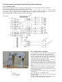
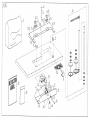
4.2 Assembly of components on the bottom of table top and connecting to the mains
- Put down antiskid (rubber) bands on the stand frame.
- Turn the table top its underside upwards and place it on the prepared bands.
- Screw on the drawer (1) using wood screws.
- Screw on the pedal position sensor holder (2) using wood screws and the pedal position sensor thereon using screws.
- Screw on the lighting transformer (3), if any, using wood screws.
- Screw on the trimmer feeder (5), if any, using wood screws.
- Connect the wiring box (6) lead to the terminals of the network lead of the electronics box (4) of the Mini-stop (8). For doing this,
it is necessary to remove the upper metal sheet and the left-hand lateral from the electronic box.
- Screw on the box (4) of the Mini-Stop (8) electronics using wood screws.
- Screw on the wiring box (6) using wood screews.
- Connect the trimmer feed (5) to the terminals X3 in the wiring box (6).
- Connect the supply of the lighting transformer (3) (if any) to the terminals X2 in the wiring box (6).
- Screw on the knee lever with the electric switch (7) (if any), using wood screws.
- Screw on the installation ducts (9) using wood screws.
- Install the electric line of the network conductors using clamps. Place the conductors, led within the Mini-stop electronics box,
into the installation ducts.
The Mini-Stop is a device of the protection class I, which means that the protection against the dangerous contact of lifeless
parts is ensured by means of a protective conductor. The Mini-Stop is destined to be connected to an
earthed alternating mains
with the voltage from 190 to 240 V 50/60 Hz. The connection thereof to the mains may be done only by means of a multipolar
plug with a protective contact. No fixed connection is permitted. Mind the uniform distribution of the power in the three-phase
mains. On every 16 A protected phase only 3 Mini-Stops may be connected, to avoid the overload of the medium conductor (N).
The MINI-STOP may be operated only with the protective conductor connected to a functional protective system
complying with all local regulations and provisions with regard to avoiding accidents of persons owing to electric
current or fire. This protection should not be cancelled e. g. by any extending cord without protective conductor.
2
1
7
3
65
4
8
9

3
The MINI-STOP will become dangerous when the protective conductor inside or outside the drive will be broken, as
well as with broken protective conductor with protective system.
Any intentional breaking thereof is forbidden.
The connecting conductors should comply with the power load and the min. HO5VV version. The conductor cross-section
should be at least 1 mm
2
, The length thereof should not exceed 5 m. The voltage on the protective conductor should not exceed
3,3 V with the 10 A current.
Caution!
The voltage in the mains must be in conformity with the voltage indicated on the drive plate.
Caution!
The transformer of the bulb for the sewing area is not switched off by the main switch (EN 60204-3-1). Before
proceeding to any repair operation in the transformer box (such as a fuse exchange) the plug categorically must be
taken out of the socket. Such operations may be carried out only by persons with adequate electrotechnical skill.
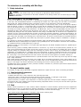
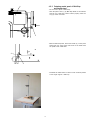
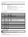
4.3 Assembly of a table top on a stand frame,
assembly of oil tank
- Turn the table top around and screw it down to the frame by
means of screw ø 8 x 35 mm.
When applying a frame different from that recommended by
the producer, be sure to adapt its position so as to ensure
the stability of the machine head in its tilted state.
- Screw on the microswitch (which is a component part of the
interconnecting cable) on the oil tank (1).
- Oil tank (1) with assembled lever (2) insert through the bot-
tom part into the cut hole in the table top and put down as
shown in detail (D) in that way, that the edge of the tank
would fit in with the edge of the cut hole in the table top. Set
the height of the tank according to the section A-A. Tank
may not protrude out of upper surface of a table top. Nail
down the tank with nails ø 2 x 40 mm.
- Adjust the lever (2) to the dimensions “B“ and “C“.
- Stick rubber inserts (3) into the cut-out of the table top.
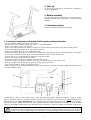
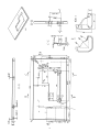
4.4 Assembly of machine head onto a stand
- Stick down rubber inlays (2) with glue into the groove in a
wedge (1) and put the wedge down on the table top (3).
- Disassemble trasported tank (cover) from the machine head
and assemble hangers (4) on the head.
- Put the head down into the rubber inlays (2) and (5).
- Screw the wedge down to the table top with screws ø 5 x
30 mm.
- Screw on hinges, using wood screw ø 5 x 40 mm and screw
M5 (the hinge above the motor), to the table top. Tighten the
wood screw and the screw in such a way, so that the oscilla-
tion of the head on rubber inserts is not limited.
- Insert supporting pin (6).
Circuit layout
124346 2
5
4
5
6
3
A(ST2)
A-A
D
B = ~82
A
A
3
3
D12
C = 9mm

4
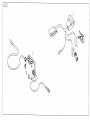
4.5 Electric connection of the machine head to the box of the drive electronics
4.5.1 Connecting cable
Together with the machine head there is supplied a connecting cable for the following drive EFKA DC 1550/DA320.
For the information sake, there are given the respective circuit layout.
The colours are indicated with numbers in brackets (6 – green, 7 – blue, 8 – pink, 9 – black, 10 – white, 11 – violet, 12 – yellow,
13 – red, 14 – grey, 15 – brown). Included insulating covers PVC (5) are put on the bunches and they are put together with
remaining part of cable insulation by means of contracted tube (4) (it is heated up with fire of lighter).
Power connecting cable is marked off with dotted line in circuit layout.
4.5.2 Propper electric connection
- Connect the 5-polar plug of the stator motor winding into
the socket B41 on the rear side of the electronics box.
- Connect the 9-polar plug of the commutation motor sensor
into the socket B2 on the rear side of the electronics box.
- Connect the 9-polar plug of the pedal sensor into the socket
on the rear side of the electronics box B80.
- Connect the 9-polar socket of the panel, if any, into the plug
on the rear side of the electronics box B776.
- Connect the 25-polar socket (3) of the connecting cable (2)
with the plug on the machine head, connect the 37-pole
plug of this cable into the 37-polar socket of the electronics
box A.
- Connect the plug of the knee lever (7) cable with its electric
switch (if any), with the socket of interconnecting cable.
- Connect the plug of the wiring box (6) cable with the socket
of interconnecting cable.
- Secure all D-SUB connectors against falling out by screwing
in the screws.
- Place the cables into the installation ducts.
- Mount the lighting, if any, and connect its cable with the
transformer cable.
- Proceed to electric interconnecting of the motor head, hinge
(8), box of the Mini-Stop electronics and stand.
823
D
D
7
6
Circuit layout
3

5
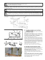
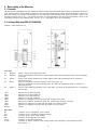
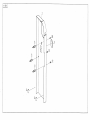
4.5.3 Fastening control panel of Mini-Stop
and thread stand
- Fix the control panel of Mini-Stop:
- Stick the panel V 810 (1) by Mini-Stop EFKA on the machine
head (if any). Defat the contact surface properly. Stick the
clip (2) on the cover belt.
- With the Mini-Stop Efka, mount the holder (4) on the panel
V820 (5)(if any) using screw and screw on the holder with
the panel to the stand table.
- Assemble the thread stand so that its arms would be parallel
to the longer edge of a table top.
1
2
60mm
80
4
5
110

6
5. Basic setting of the Mini-stop
5.1 Generally
The Mini-stop DC 1550/DA320 does not necessarily need the control panel V810/VV820 when running. All parameters can be set
using push the buttons and the display on electronics box, the panel V810/V820 will however enable the operator to work more
easily with regard to its position. The description of the push-button panel and that of the panels V810/V820 is given in the
instruction manual, part A, par. 7. The general procedure of setting parameters with the panel V8120/V820 is given in the
assembling instructions with standard drives, part. B1, par. 5.1 and appllies also to DC 1550/DA320.
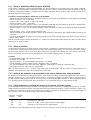
5.2 Setting of Mini-stop EFKA DC 1550/DA320
Elements of the electronics box
Front side
S1 Button P calling or leaving the programming mode
S2 Button E option of initial bartack (switched off, simple, double) within the programming mode of the confirmation
of changes
S3 Button + option of final bartack (switched off, simple, double) within theprogramming mode of enhancing
the displayed value
S4 Button - position of the presser foot when stopping in the seam (down, up)
position of the presser foot after trimming (down, up) within the programmed mode of reduction of
the displayed value
S5 Button » position of the needle when stopping in the seam (down, up) within the programming mode of shifting to
the next digit
LED1 indication for the start single bar
LED2 indication for the start double bar
LED3 indication for the end single bar
LED4 indication for the end double bar
LED5 ndication for automatic presser foot lifting when stopping in the seam
LED6 indication for automatic presser foot lifting after having ended the seam (trimming)
LED7 indication for stopping in the seam with the needle in its bottom position
LED8 indication for stopping in the seam with the needle in its top position
Display 3 digits
Reae side
B2 connection of the commutating motor scanner
B18 connection of the light barrier module (photocell)
B41 connection of the motor stator winding
B80 connection of the pedal set value initiator
B776 connection of the panel V810/V820
A (ST2) connection of electric elements of the sewing machine (electromagnets, electropneumatic valves,
push-buttons …)

7
5.2.1 Setting of parameters without the panel V810/V820
The procedure is identical as with the panel V810/V820, only the representation on the display having only 3 digits is different.
In this way, the numerical values of parameters containing more than 3 digits (e.g. 2000 rev/min being represented as 200) are
shortened. The parameter number is displayed with three digits with three decimal points to differ it from the value of the
parameter displayed without points.
Procedure of changing parameters without the panel V810/V820
- depress the button P and then switch on the network switch on the front side of the electronics box, the display will show Cod
- depress the button », the 1
st
digit blinks
- using the button + and -, set the 1
st
digit to the value 3
- depress the button », the 2
nd
digit blinks
- in the same way, set the 2
nd
and the 3
rd
digits, so that the display shows 311 (the code number for the access to all parameters)
- depress the button E, the display will show 2.0.0 (parameter number 200)
- using the buttons », + and -, set the required parameter number and depress the button E, the display will show the parameter
value
- using the buttons + and -, set the required parameter value
- depress the button E (the following parameter number will be displayed) or the button P (the original parameter number will be
displayed)
- proceed to the termination of changes by depressing the button P (you will leave the programming mode) and you will return
into the sewing mode
Note: To store the change in memory permanently, it is necessary to tread the pedal forward (sewing of at least one sticth) before
switching of the network switch.
5.2.2 Setting of positions
The mechanical connection of the motor with the sewing machine is enabled by an indented belt with the gear speed ration of
1:1.This ensures constant angular ratios between the motor rotor and the sewing machine. The hand wheel synchronizer replaces
the synchronizer, which is built-in in the motor. When removing for any reason the indented belt, a new setting of the correct
angular ratio between the motor and the sewing machine, the so-called reference position, is necessary.
Procedure
- set the parameter number 170¸ depress the button E
- the display will show Sr1
- depress the button », Po will be displayed (the symbol o is rotating)
- turn the handwheel, until the rotating symbol o disappears and P is displayed
- turn now the handwheel to the value of the angle 105° (the needle point is at the level of the throat plate)
- depress 2x the button P (return into the sewing mode)
Other important positions, i.e the 1
st
position of the needle given by the parameter 171 1E and the 2
nd
position given by the
parameter 171 2 E have been preset by the manufacturer of the drive.
5.2.3 Setting of the parameter of the microswitch of the running blocking when tilting the machine
For the purpose of enhancing the safety of the operator of the machine and when unintentionally treading the pedal, the motor
running is blocked. To get a correct working of this function, it is necessary to mount a microswith (which is component part of
the interconnecting cable) on the rear side of the oil tray and to set the parameter 282 to the value 1 . When the machine head is
in its working position, the microswitch must be switched on. The microswitch can be set when bending its lever.
5.2.4 Setting parameters for reducing the pressure of the presser foot when stopping
The electromagnet serving for lifting the presser foot may dispose also of a function for reducing the pressure or for lifting
slightly the preser foot when turning the sewn upper parts after having stopped in the seam or when the machine is running. This
command can be given by the operator by depressing the first button to the right on the button panel or by foot (microswitch of
the knee lever). This function needs setting of the following parameters:
Parameter Parameter
number value
250 12 function of reducing the presser foot pressure
332 1 the setting 333, 334 holds
333 *40 time in ms of max. current of the presser foot electromagnet
334 *60 retaining force of the presser foot electromagnet
* the values are only approximative ones and depend on the set up pressure of the presser foot and on the material thickness

8
5.2.5 Changes of setting parameters of the Mini-stop with regard to the original setting of the manufacturer
Parameter Parameter
number value
111 - maximum revolutions (according to the machine type)
116 180 revolutions of the trimmer
135 1 fancy bar
170 - reference position
192 147 angle of the delay of switching on the tensioner
215 0 the last advancing section of the start bar counted
250 12 function of the outlet A/30 and of the inlet A/8 (reduction of the presser foot pressure)
282 1 see 5.2.3
332 1 the setting 333, 334 holds
333 *40 time in ms of max. current of the presser foot electromagnet
334 *60 retaining force of the presser foot electromagnet
* the values are only approximative ones and depend on the set up pressure of the presser foot and on the material thickness
5.2.6 Indication of faults
Generation information
Display of the V810 V820 Meaning
electronics box
A1 InF A1 InF A1 When switching on the machine, the pedal is not in the zero position.
-StoP- blinks +
A2 -StoP- blinks symbol blinks Blocking of the motor running.
A3 InF A3 InF A3 The reference position is not set.
A5 InF A5 InF A5 Autoselect not set or erroneous.
Programming of functions and values
Display of the V810 V820 Meaning
electronics box
Jump back to 000 Jumb back to 000
or to the last or to the last InF F1 Erroneous code or parameter number inserted.
parameter number parameter number
Serious state
Display of the V810 V820 Meaning
electronics box
E2 InF E2 InFo E2 Low woltage in the network or short period of time between the network switching on and off.
E3 InF E3 InFo E3 Machine blocked or without attaining the required revolutions.
E4 InF E4 InFo E4 Interference due to insufficient earthing or defective contact.
Hardware failure
Display of the V810 V820 Meaning
electronics box
H1 InF H1 InFo H1 Commutation signal or invertor defective.
H2 InF H2 InFo H2 Processor defective.
6. Examination of sewing
Caution! Risk of injury!
Before threading a thread switch the main switch off and wait until the motor stops.
- Check the sense of turning the hand wheel – according to the arrow situated on it.
- Thread a thread.
- Choose sewing material.
- Switch the desirable function on the control panel of stopmotor. Examination should be carried out with selection of fancy bar.
- First sew slowly then speed up the sewing.
- If the stitch does not meet requirements, follow the first part of instructions manual or service book.

9


Pos. Dílec è. Název
Det. Part No. Denomination
Pos. Dílec è. Název
Det. Part No. Denomination
TAB.
M 252
3 ...... S080 826387 .............................................. PØÍCHYTKA ............................................ CLIP
4 ...... 0104 250010............................................... KRYT....................................................... COVER
8 ...... 0907 010050............................................... VLO•KA .................................................. INSERT
9 ...... S273 940127 .............................................. VLO•KA .................................................. INSERT
10 ...... S311 400030 .............................................. VRUT 5 x 30 ........................................... SCREW 5 x 30
11 ...... S311 400040 .............................................. VRUT 5 x 40 ........................................... SCREW 5 x 40
12 ...... 9840 123002............................................... HØEB ...................................................... NAIL
13 ...... S321 026000 .............................................. ÈEPIÈKA 16 x 26 .................................... CAP 16 x 26
14 ...... S321 953251 .............................................. MISKA .................................................... DISH
15 ...... S345 172000 .............................................. KABEL. PØÍCHYTKA ............................... CABLE CLIP
16 ...... S980 061238 .............................................. KLÍN ........................................................ WEDGE
17 ...... S615 932046 .............................................. KOLÍK ..................................................... PIN
18 ...... S708 130003 .............................................. KNOT MAZACÍ ........................................ WICK LUBRICATING
21 ...... S980 057274 .............................................. OLEJOVÁ VANA ÚPLNÁ ......................... OIL TRAY CPL.
22 ...... S981 094058 .............................................. ELEKTROINSTALAÈNÍ MATERIÁL ......... MATERIAL OF EL.INSTALATION
23 ...... S980 060198 .............................................. ZÁVÌS ÚPLNÝ ........................................ HANGER CPL.
24 ...... S309 798025 .............................................. ŠROUB.................................................... SCREW
25 ...... S981 036162 .............................................. NI•. STOJÁNEK PRO JEDNOJEHL.ST.... THREAD STAND FOR SINGLE-
.............................................................................................................................................. NEEDLE MACHINES
30 ...... S080 314210 .............................................. HØÍDEL ................................................... SHAFT
31 ...... S080 941107 .............................................. KROU•EK ............................................... RING
32 ...... S080 625022 .............................................. NARÁ•KA ............................................... STOP
33 ...... S080 141141 .............................................. ŠROUB.................................................... SCREW
34 ...... S283 068001 .............................................. HADIÈKA PVC ........................................ HOSE PVC
35 ...... S080 264339 .............................................. PRU•INA ................................................ SPRING
36 ...... S981 027603 .............................................. PÁKA ÚPLNÁ .......................................... LEVER CPL.
44 ...... S080 625186 .............................................. PÁKA....................................................... LEVER
45 ...... S080 120295 .............................................. ŠROUB.................................................... SCREW
46 ...... S311 732060 .............................................. POJIŠ•OVACÍ KROU•EK........................ RETAINING RING
47 ...... S080 318238 .............................................. ÈEP ......................................................... PIN
48 ...... S080 418183 .............................................. KLADKA .................................................. ROLLER
52 ............................................................................ Dokumentace dle typu stroje ................. Documentation of the machine type
60 ...... 0052 000369............................................... OLEJNIÈKA ............................................. OIL CAN


Pos. Dílec è. Název
Det. Part No. Denomination
Pos. Dílec è. Název
Det. Part No. Denomination
TAB.
M 266
1 ...... S980 057270 .............................................. KRYT ÚPLNÝ ......................................... COVER CPL.
6 ...... S321 833821 .............................................. ZÁTKA ..................................................... PLUG
8 ...... S080 146058 .............................................. ŠROUB ................................................... SCREW
9 ...... S080 940177 .............................................. DORAZ .................................................... STOP
10 ...... S309 738406 .............................................. ŠROUB ................................................... SCREW


Pos. Dílec è. Název
Det. Part No. Denomination
Pos. Dílec è. Název
Det. Part No. Denomination
TAB.
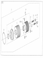
M 299
3 ...... S981 045563 .............................................. POJISTNÁ SPOJKA ÚPLNÁ ................... SAFETY CLUTCH CPL.
4 ...... S981 045565 .............................................. ØEMENICE ÚPLNÁ ................................. PULLEY CPL.
5 ............................................................................ VIZ POS. 4 .............................................. SEE 4
6 ............................................................................ VIZ POS. 4 .............................................. SEE 4
7 ............................................................................ VIZ POS. 4 .............................................. SEE 4
9 ............................................................................ VIZ POS. 4 .............................................. SEE 4
10 ...... S080 318244 .............................................. ÈEP ......................................................... PIN
11 ...... 0067 001770............................................... PRU•INA ................................................ SPRING
12 ...... S080 156054 .............................................. ŠROUB.................................................... SCREW
13 ............................................................................ VIZ POS. 3 .............................................. SEE 3
15 ...... S080 274152 .............................................. KROU•EK ............................................... RING
23
24
30


Pos. Dílec è. Název
Det. Part No. Denomination
Pos. Dílec è. Název
Det. Part No. Denomination
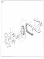
TAB.
M 300
1 ...... S080 836488 .............................................. DR•ÁK .................................................... HOLDER
3 ...... S080 111236 .............................................. ŠROUB.................................................... SCREW
4 ...... S981 045566 .............................................. ØEMENICE ÚPLNÁ ................................. PULLEY CPL.
5 ...... S080 146064 .............................................. ŠROUB.................................................... SCREW
6 ...... 9202 002908............................................... ŠROUB.................................................... SCREW
7 ...... S309 543512 .............................................. ŠROUB.................................................... SCREW
8 ...... S272 100519 .............................................. OZUBENÝ ØEMEN .................................. TOOTHED BELT
9 ...... S080 831710 .............................................. KRYT ....................................................... COVER
10 ...... S309 000510 .............................................. ŠROUB.................................................... SCREW


Pos. Dílec è. Název
Det. Part No. Denomination
Pos. Dílec è. Název
Det. Part No. Denomination
TAB.
M 302
1 ...... S980 094066 .............................................. PROPOJOVACÍ KABEL.......................... CONNECTING CABLE
2 ...... S980 094070 .............................................. ROZVOD ................................................. DISTRIBUTION BOX
-
 1
1
-
 2
2
-
 3
3
-
 4
4
-
 5
5
-
 6
6
-
 7
7
-
 8
8
-
 9
9
-
 10
10
-
 11
11
-
 12
12
-
 13
13
-
 14
14
-
 15
15
-
 16
16
-
 17
17
-
 18
18
-
 19
19
-
 20
20


in altre lingue
- English: DURKOPP ADLER 4181
Documenti correlati
-
DURKOPP ADLER 4220 Manual Motor
-
DURKOPP ADLER 4180 Manual Motor
-
-
-
-
-
-
-
 Duerkopp Adler 271 - 274 Manuale del proprietario
-
 Duerkopp Adler 550-5-5-2 Istruzioni per l'uso

