
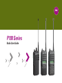
P100 Series
Radio User Guide


i
English
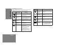
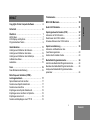
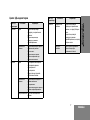
CONTENTS
CONTENTS
Computer Software
Copyrights . . . . . . . . . . . . . . . . . . . . . . . . . . . . . . . . ii
Safety . . . . . . . . . . . . . . . . . . . . . . . . . . . . . . . . . . . . iii
Radio Overview . . . . . . . . . . . . . . . . . . . . . . . . . . . . 1
LED Colors . . . . . . . . . . . . . . . . . . . . . . . . . . . . . . . . . . 7
LCD Display and Icons . . . . . . . . . . . . . . . . . . . . . . . . . 8
Programmable Buttons . . . . . . . . . . . . . . . . . . . . . . . . . 9
Getting Started . . . . . . . . . . . . . . . . . . . . . . . . . . . . . 11
Attaching and Removing the Antenna . . . . . . . . . . . . . 11
Attaching and Removing the Battery . . . . . . . . . . . . . . 12
Attaching and Removing the Belt Clip . . . . . . . . . . . . . 13
Charging the Battery . . . . . . . . . . . . . . . . . . . . . . . . . . 14
Charging Status . . . . . . . . . . . . . . . . . . . . . . . . . . . . . . 15
Scan . . . . . . . . . . . . . . . . . . . . . . . . . . . . . . . . . . . . . 16
Deleting a Nuisance Scan Channel . . . . . . . . . . . . . . . 16
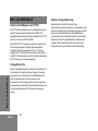
Dual Tone Multiple Frequency
(DTMF) Features . . . . . . . . . . . . . . . . . . . . . . . . . . . 17
Voice Selective Call and Call Alert . . . . . . . . . . . . . . . 17
Transmitting a Voice Selective Call . . . . . . . . . . . . . . . 17
Transmitting a Call Alert . . . . . . . . . . . . . . . . . . . . . . . 17
Receiving a Voice Selective Call . . . . . . . . . . . . . . . . . 18
Receiving a Call Alert with Voice . . . . . . . . . . . . . . . . . 18
Receiving a Call Alert . . . . . . . . . . . . . . . . . . . . . . . . . 18
Transmitting and Receiving a PTT ID . . . . . . . . . . . . .18
Phone Mode . . . . . . . . . . . . . . . . . . . . . . . . . . . . . . 19
MDC-1200 Features . . . . . . . . . . . . . . . . . . . . . . . . 20
Quik-Call II Features . . . . . . . . . . . . . . . . . . . . . . . 21
Voice Operated Transmit (VOX) . . . . . . . . . . . . . . 22
To Start the VOX Feature . . . . . . . . . . . . . . . . . . . . . .22
To Disable the VOX Feature . . . . . . . . . . . . . . . . . . . .22
To Re-enable the VOX Feature . . . . . . . . . . . . . . . . . .22
Voice Inversion Scrambling . . . . . . . . . . . . . . . . . 23
To Enable and Disable the
Scrambling Mode . . . . . . . . . . . . . . . . . . . . . . . . . . . . .23
To Change the Scrambling Code . . . . . . . . . . . . . . . . .23
Front Panel Programming Mode . . . . . . . . . . . . . . 24
Entering Front Panel Programming Mode . . . . . . . . . .24
Exiting Front Panel Programming Mode . . . . . . . . . . .24
Assessing Front Panel Programming Mode
Parameters . . . . . . . . . . . . . . . . . . . . . . . . . . . . . . . . . .24

ii
COMPUTER SOFTWARE
COPYRIGHTS
English
COMPUTER SOFTWARE
COPYRIGHTS
The Motorola products described in this manual may
include copyrighted Motorola computer programs stored
in semiconductor memories or other media. Laws in the
United States and other countries preserve for Motorola
certain exclusive rights for copyrighted computer
programs, including, but not limited to, the exclusive right
to copy or reproduce in any form the copyrighted
computer program. Accordingly, any copyrighted
Motorola computer programs contained in the Motorola
products described in this manual may not be copied,
reproduced, modified, reverse-engineered, or distributed
in any manner without the express written permission of
Motorola.
Furthermore, the purchase of Motorola products shall not
be deemed to grant either directly or by implication,
estoppel, or otherwise, any license under the copyrights,
patents or patent applications of Motorola, except for the
normal non-exclusive license to use that arises by
operation of law in the sale of a product.

English
SAFETY
iii
SAFETY
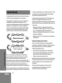
PRODUCT SAFETY AND RF EXPOSURE
COMPLIANCE
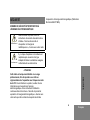
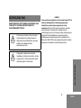
ATTENTION!
This radio is restricted to occupational use only to
satisfy FCC RF energy exposure requirements. Before
using this product, read the RF energy awareness
information and operating instructions in the Product
Safety and RF Exposure booklet enclosed with your radio
(Motorola Publication part number 6864117B25) to
ensure compliance with RF energy exposure limits.
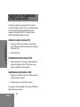
Before using this product, read the
operating instructions for safe usage
contained in the Product Safety and RF
Exposure booklet enclosed with your radio.
Risk of explosion could happen if battery is
replaced by an incorrect type. Dispose of
any used batteries according to
instructions.
C a u t i o n
C a u t i o n

SAFETY
iv
English
Notes

1
English
RADIO OVERVIEW
English
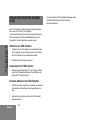
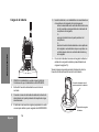
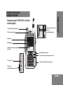
RADIO OVERVIEW
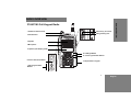
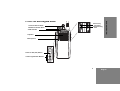
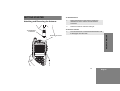
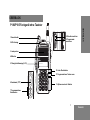
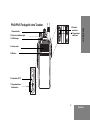
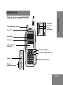
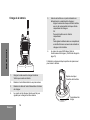
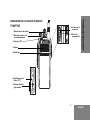
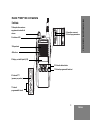
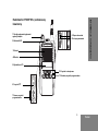
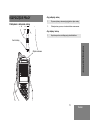
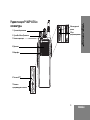
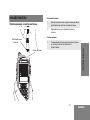
11 Front Programmable Buttons
10 Left/Right Button
8 Accessory Connector
12 Alphanumeric Keypad
9 Programming Port
4 Microphone
3 Speaker
P180/P185 Full Keypad Radio
6 Push-to-Talk (PTT) Button
5 Liquid Crystal Display (LCD)
2 LED Indicator
1 On/Off and Volume Knob
7 Side Programmable
Buttons

RADIO OVERVIEW
2
English
English
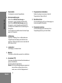
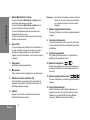
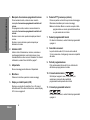
1. On/Off and Volume Knob
Turn the ON/OFF/Volume Control knob clockwise to turn
the radio ON.
Turn the ON/OFF/Volume Control knob
counterclockwise to turn the radio OFF.
Turn this knob clockwise to increase the volume.
Turn this knob counterclockwise to decrease the volume.
2. LED Indicator
Indicates radio transmit, receive, scan and monitor status,
as well as receipt of a selective call or call alert. Refer to
"LED Colors" on page 7 for more information.
3. Speaker
Receives audio messages through the speaker.
4. Microphone
Speak into the microphone when sending messages.
5. Liquid Crystal Display (LCD)
An 8 character single line display with up to 10 radio
status icons. Refer to "LCD Display and Icons" on page 8
for more details.
6. Push-to-Talk (PTT) Button
Press and speak to microphone to send message.
Release and listen to receive messages.
Note: If a channel is programmed with the Busy Channel
Lockout feature, the user can only transmit if the
channel is not in receiving mode.
7. Side Programmable Buttons
Refer to "Programmable Buttons" on page 9 for more
details.
8. Accessory Connector
2.5 mm audio in port and 3.5 mm audio out port are used
to connect compatible accessories to the radio.
9. Programming Port
2.5 mm audio in lower port used by dealer to program the
radio.
10. Left/Right Button
Used to navigate menu, sub-menu or parameter
selections in front panel programming mode.
11. Front Programmable Buttons
Refer to "Programmable Buttons" on page 9 for more
details.
12. Alphanumeric Keypad
Allows alphanumeric entry in the front panel programming
and numeric entry in Dual Tone Multiple Frequency
(DTMF) dialing or phone mode.

3
English
RADIO OVERVIEW
English
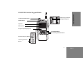
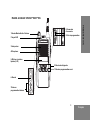
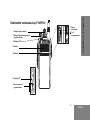
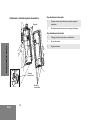
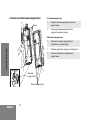
10 Left/Right Button
11 Front Programmable Buttons
1 On/Off and Volume Knob
2 LED Indicator
3 Speaker
4 Microphone
5 Liquid Crystal Display (LCD)
6 Push-to-Talk (PTT) Button
7 Side Programmable
Buttons
P160/P165 Limited Keypad Radio
9 Programming Port
8 Accessory Connector

RADIO OVERVIEW
4
English
English
1. On/Off and Volume Knob
Used to select channels in normal radio operation mode.
Turn the ON/OFF/Volume Control knob clockwise to turn
the radio ON.
Turn the ON/OFF/Volume Control knob
counterclockwise to turn the radio OFF.
Turn this knob clockwise to increase the volume.
Turn this knob counterclockwise to decrease the volume.
2. LED Indicator
Indicates radio transmit, receive, scan and monitor status,
as well as receipt of a selective call or call alert. Refer to
"LED Colors" on page 7 for more information.
3. Speaker
Receives audio messages through the speaker.
4. Microphone
Speak into the microphone when sending messages.
5. Liquid Crystal Display (LCD)
An 8 character single line display with up to 10 radio
status icons. Refer to "LCD Display and Icons" on page 8
for more details.
6. Push-to-Talk (PTT) Button
Press and speak to microphone to send message.
Release and listen to receive messages.
Note: If a channel is programmed with the Busy Channel
Lockout feature, the user can only transmit if the
channel is not in receiving mode.
7. Side Programmable Buttons
Refer to "Programmable Buttons" on page 9 for more
details.
8. Accessory Connector
2.5 mm audio in port and 3.5 mm audio out port are used
to connect compatible accessories to the radio.
9. Programming Port
2.5 mm audio in lower port used by dealer to program the
radio.
10. Left/Right Button
Used to navigate menu, sub-menu or parameter
selections in front panel programming mode.
11. Front Programmable Buttons
Refer to "Programmable Buttons" on page 9 for more
details
.

5
English
RADIO OVERVIEW
English
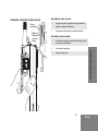
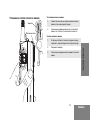
6 Push-to-Talk (PTT) Button
5 Microphone
4 Speaker
3 LED Indicator
2 On/Off and Volume Knob
7 Side Programmable Buttons
8 Accessory
Connector
9 Programming
Port
P140/P145 Non-Keypad Radio
1 Channel Selector Knob

RADIO OVERVIEW
6
English
English
1. Channel Selector Knob
Used to select channels in normal radio operation mode.
2. On/Off and Volume Knob
Turn the ON/OFF/Volume Control knob clockwise to turn
the radio ON.
Turn the ON/OFF/Volume Control knob counterclockwise
to turn the radio OFF.
Turn this knob clockwise to increase the volume.
Turn this knob counterclockwise to decrease the volume.
3. LED Indicator
Indicates radio transmit, receive, scan and monitor status,
as well as receipt of a selective call or call alert. Refer to
"LED Colors" on page 7 for more information.
4. Speaker
Receives audio messages through the speaker.
5. Microphone
Speak into the microphone when sending messages.
6. Push-to-Talk (PTT) Button
Press and speak to microphone to send message.
Release and listen to receive messages.
Note: If a channel is programmed with the Busy Channel
Lockout feature, the user can only transmit if the
channel is not in receiving mode.
7. Side Programmable Buttons
Refer to "Programmable Buttons" on page 9 for more
details.
8. Accessory Connector
2.5 mm audio in port and 3.5 mm audio out port are used
to connect compatible accessories to the radio.
9. Programming Port
2.5 mm audio in lower port used by dealer to program the
radio.

7
English
RADIO OVERVIEW
English
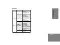
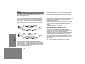
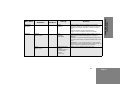
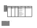
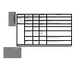
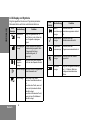
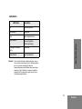
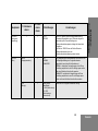
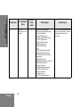
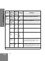
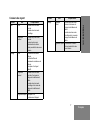
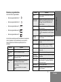
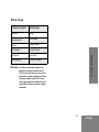
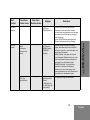
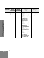
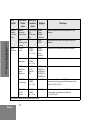
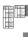
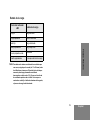
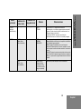
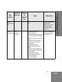
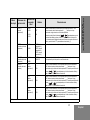
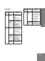
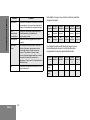
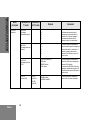
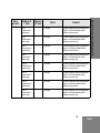
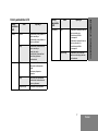
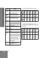
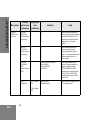
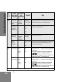
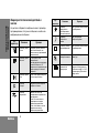
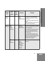
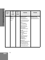
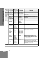
LED Colors
LED Color State Indication
Green
Illuminated Radio is transmitting in
normal mode.
Radio is transmitting in
Scrambling Mode.
Normal Blinking Radio is receiving in normal
mode.
Channel is busy.
Radio passed self-test
during powering up.
Amber Illuminated Monitor activated.
Permanent Sticky Monitor
activated.
Selective Call received.
Normal Blinking Radio is in active Scan
Mode.
Radio is receiving in
Scrambling Mode.
Fast Blinking Call Alert received.
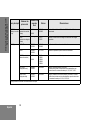
Red Normal Blinking Radio is transmitting in
normal mode while battery is
low.
Radio is transmitting in
Scrambling Mode while
battery is low.
Fast Blinking Radio failed self-test during
powering up.

RADIO OVERVIEW
8
English
English
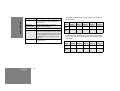
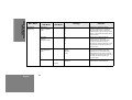
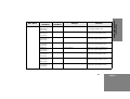
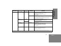
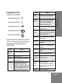
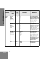
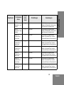
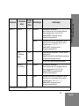
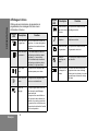
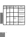
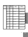
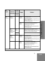
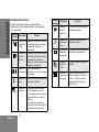
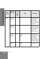
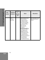
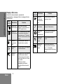
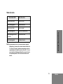
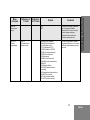
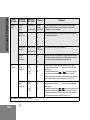
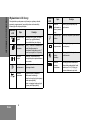
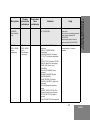
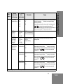
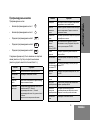
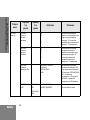
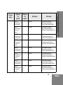
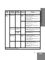
LCD Display and Icons
Displays selected channel, programming parameters, status
messages and any error or information messages.
LCD
Indicator
Description Function
Signal Strength
Indicator
Shows the signal strength. More
bars indicate a stronger signal
received by radio.
Power Level
Indicator
“L” illuminates to indicate radio is
configured to transmit in low
power; “H” illuminates when radio
transmits in high power.
Talkaround
Indicator
Illuminates when radio is not
transmitting through the repeater.
Monitor
Indicator
Illuminates when monitoring a
selected channel.
Scan Indicator Blinks without dot when normal
scan is activated.
Illuminates without dot when
there is some activity on a
non-priority channel.
Illuminates with dot blinking to
indicate that there is some
activity on the priority channel.
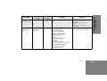
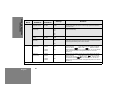
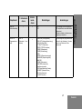
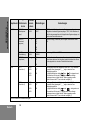
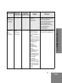
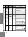
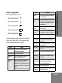
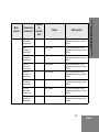
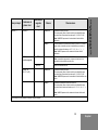
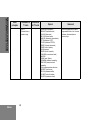
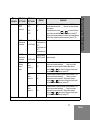
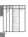
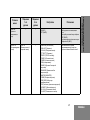
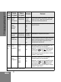
LCD
Indicator
Description Function
Voice Inversion
Scrambling
Indicator
Illuminates when Scrambling
Mode is on.
Phone Mode
Indicator
Illuminates when Phone Mode is
selected.
Programming
Mode Indicator
Illuminates when Programming
Mode is on.
Keypad Lock
Indicator
Illuminates when keypad is
locked.
Battery Level
Indicator
Shows remaining charge in
battery based on how many bars
(1 – 3) are displayed. Blinks
when the battery is low.

9
English
RADIO OVERVIEW
English
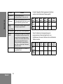
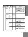
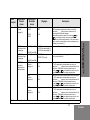
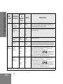
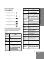
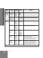
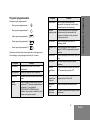
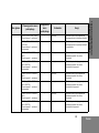
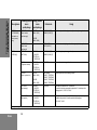
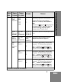
Programmable Buttons
The programmable buttons consist of:
• Side Programmable Button 1
• Side Programmable Button 2
• Front Programmable Button 1
• Front Programmable Button 2
• Front Programmable Button 3
The following functions can be assigned as short press i.e
press and release; or long press i.e. press and hold for more
than 1 second.
Button Function
Backlight Toggles backlight display between ON and
OFF.
Call Alert Initiates Call Alert.
Channel Alias Toggles display between Channel Number
and Channel Alias.
Keypad Lock Locks or unlocks all buttons except PTT, Side
Programmable Button 1, Side Programmable
Button 2 and ON/OFF/Volume Knob.
Applicable for Long Press only.
Button Function
Monitor Monitors the channel for any activity as long
as the button is pressed.
Nuisance
Channel Delete
Removes unwanted channel(s) temporarily
from scan list during Scan. Applicable for Long
Press only.
Phone Mode Enables or disables Phone feature for the
selected channel.
TPL/DPL Enable Enables or disables radio from requiring
matching TPL/DPL to unsquelch.
Power Level Selects required power level: High or Low.
Prime Channel Enables quick move to the selected Prime
Channel.
PTT ID Enable Enables or disables PTT ID sent on PTT
press.
Reverse Burst Selects the Reverse Burst Type: None, 180 or
240.
Channel Scan Starts or stops Channel Scan.
Scrambling Code
Select
Toggles between the two scrambling codes
available.
Scrambling
Enable/Disable
Enables or disables scrambling feature for the
selected channel. Applicable for Long Press
only.
Selective Call Initiates Selective Call.
Squelch Level Selects desired squelch level: Normal or Tight.

RADIO OVERVIEW
10
English
English
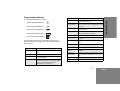
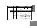
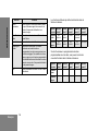
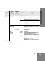
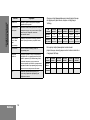
The default functions assigned to your radio are described in
the table below
.
If your dealer has reprogrammed your radio’s programmable
buttons, you may want to write down the new functions in the
table below.
Button Function
Sticky Monitor Toggles the permanent monitor function until
the button is pressed again. Applicable for
Long Press only.
Talkaround/
Repeater Mode
Enables toggle between repeater and
talkaround mode operations.
Unassigned No function is programmed to this button.
Volume Set Controls the audio level. The button emits a
continuous tone to indicate the current volume
level. To change volume level, turn the volume
knob to the desired level while pressing the
programmable button. Applicable for Long
Press only.
VOX Enables or disables VOX feature for the
selected channel.
Press
Type
Side
Button 1
Side
Button 2
Front
Button 1
Front
Button 2
Front
Button 3
Short
Press
Unassigned Unassigned Monitor Power
Level
Unassigned
Long
Press
Unassigned Unassigned Unassigned Unassigned Unassigned
Press
Type
Side
Button 1
Side
Button 2
Front
Button 1
Front
Button 2
Front
Button 3
Short
Press
Long
Press

11
English
GETTING STARTED
GETTING STARTED
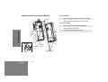
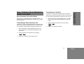
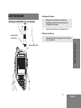
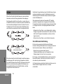
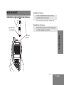
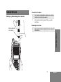
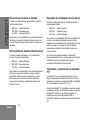
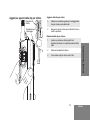
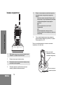
Attaching and Removing the Antenna
To Attach Antenna
To Remove Antenna
Antenna Connector
Threaded End
of Antenna
1. Fasten the antenna to the radio by placing the
threaded end of the antenna into the Antenna
Connector.
2. Rotate the antenna clockwise until tight.
1. Turn the antenna in a counterclockwise direction until
it disengages from the radio.

12
English
GETTING STARTED
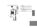
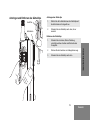
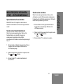
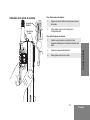
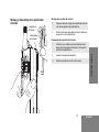
Attaching and Removing the Battery To Attach Battery
To Remove Battery
Battery Slots
Grooves
Battery
Latch
1. Fit the battery slots with the grooves on the radio.
2. Slide the battery upwards until a click is heard.
1. Slide the battery latch away from the radio.
2. Slide the battery downwards.
3. Pull the battery away from the radio.

13
English
GETTING STARTED
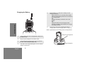
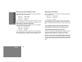
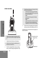
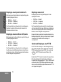
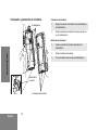
Attaching and Removing the Belt Clip
To Attach Belt Clip
To Remove Belt Clip
Release Tab
Mounting Grooves
1. Align mounting rails of the belt clip with the grooves
of the radio.
2. Slide the belt clip downwards until it clicks into place.
1. Safely insert a flat tool between the release tab and
the back surface of the radio.
2. Lift the release tab.
3. Slide the belt clip upwards.

14
English
GETTING STARTED
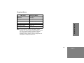
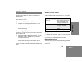
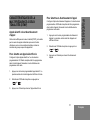
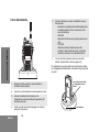
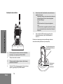
Charging the Battery
Refer to picture below for the battery insert visual guide line.
1. Turn the radio OFF when charging battery. Make sure
the radio is OFF.
2. Plug the power supply into an electric outlet.
3. Connect the power supply output cord connector into
the rear of the Desktop Charging Tray.
4. The LED on the charger blinks green once to indicate
charger is turned ON.
5. Insert a battery, or a radio with a battery into the
charger’s pocket by:
aligning the groove on each side of the battery
with the corresponding raised rail on each side of
the charger pocket
OR
pressing the battery towards the rear of the
pocket
OR
sliding the battery into the charger pocket,
ensuring complete contact between the charger
and battery contacts.
6. The charger’s LED color indicates the battery’s
charging status. (See Charging Status on page 15).
Battery insert visual guide line
Battery Charging Tray
La pagina sta caricando ...
La pagina sta caricando ...
La pagina sta caricando ...
La pagina sta caricando ...
La pagina sta caricando ...
La pagina sta caricando ...
La pagina sta caricando ...
La pagina sta caricando ...
La pagina sta caricando ...
La pagina sta caricando ...
La pagina sta caricando ...
La pagina sta caricando ...
La pagina sta caricando ...
La pagina sta caricando ...
La pagina sta caricando ...
La pagina sta caricando ...
La pagina sta caricando ...
La pagina sta caricando ...
La pagina sta caricando ...
La pagina sta caricando ...
La pagina sta caricando ...
La pagina sta caricando ...
La pagina sta caricando ...
La pagina sta caricando ...
La pagina sta caricando ...
La pagina sta caricando ...
La pagina sta caricando ...
La pagina sta caricando ...
La pagina sta caricando ...
La pagina sta caricando ...
La pagina sta caricando ...
La pagina sta caricando ...
La pagina sta caricando ...
La pagina sta caricando ...
La pagina sta caricando ...
La pagina sta caricando ...
La pagina sta caricando ...
La pagina sta caricando ...
La pagina sta caricando ...
La pagina sta caricando ...
La pagina sta caricando ...
La pagina sta caricando ...
La pagina sta caricando ...
La pagina sta caricando ...
La pagina sta caricando ...
La pagina sta caricando ...
La pagina sta caricando ...
La pagina sta caricando ...
La pagina sta caricando ...
La pagina sta caricando ...
La pagina sta caricando ...
La pagina sta caricando ...
La pagina sta caricando ...
La pagina sta caricando ...
La pagina sta caricando ...
La pagina sta caricando ...
La pagina sta caricando ...
La pagina sta caricando ...
La pagina sta caricando ...
La pagina sta caricando ...
La pagina sta caricando ...
La pagina sta caricando ...
La pagina sta caricando ...
La pagina sta caricando ...
La pagina sta caricando ...
La pagina sta caricando ...
La pagina sta caricando ...
La pagina sta caricando ...
La pagina sta caricando ...
La pagina sta caricando ...
La pagina sta caricando ...
La pagina sta caricando ...
La pagina sta caricando ...
La pagina sta caricando ...
La pagina sta caricando ...
La pagina sta caricando ...
La pagina sta caricando ...
La pagina sta caricando ...
La pagina sta caricando ...
La pagina sta caricando ...
La pagina sta caricando ...
La pagina sta caricando ...
La pagina sta caricando ...
La pagina sta caricando ...
La pagina sta caricando ...
La pagina sta caricando ...
La pagina sta caricando ...
La pagina sta caricando ...
La pagina sta caricando ...
La pagina sta caricando ...
La pagina sta caricando ...
La pagina sta caricando ...
La pagina sta caricando ...
La pagina sta caricando ...
La pagina sta caricando ...
La pagina sta caricando ...
La pagina sta caricando ...
La pagina sta caricando ...
La pagina sta caricando ...
La pagina sta caricando ...
La pagina sta caricando ...
La pagina sta caricando ...
La pagina sta caricando ...
La pagina sta caricando ...
La pagina sta caricando ...
La pagina sta caricando ...
La pagina sta caricando ...
La pagina sta caricando ...
La pagina sta caricando ...
La pagina sta caricando ...
La pagina sta caricando ...
La pagina sta caricando ...
La pagina sta caricando ...
La pagina sta caricando ...
La pagina sta caricando ...
La pagina sta caricando ...
La pagina sta caricando ...
La pagina sta caricando ...
La pagina sta caricando ...
La pagina sta caricando ...
La pagina sta caricando ...
La pagina sta caricando ...
La pagina sta caricando ...
La pagina sta caricando ...
La pagina sta caricando ...
La pagina sta caricando ...
La pagina sta caricando ...
La pagina sta caricando ...
La pagina sta caricando ...
La pagina sta caricando ...
La pagina sta caricando ...
La pagina sta caricando ...
La pagina sta caricando ...
La pagina sta caricando ...
La pagina sta caricando ...
La pagina sta caricando ...
La pagina sta caricando ...
La pagina sta caricando ...
La pagina sta caricando ...
La pagina sta caricando ...
La pagina sta caricando ...
La pagina sta caricando ...
La pagina sta caricando ...
La pagina sta caricando ...
La pagina sta caricando ...
La pagina sta caricando ...
La pagina sta caricando ...
La pagina sta caricando ...
La pagina sta caricando ...
La pagina sta caricando ...
La pagina sta caricando ...
La pagina sta caricando ...
La pagina sta caricando ...
La pagina sta caricando ...
La pagina sta caricando ...
La pagina sta caricando ...
La pagina sta caricando ...
La pagina sta caricando ...
La pagina sta caricando ...
La pagina sta caricando ...
La pagina sta caricando ...
La pagina sta caricando ...
La pagina sta caricando ...
La pagina sta caricando ...
La pagina sta caricando ...
La pagina sta caricando ...
La pagina sta caricando ...
La pagina sta caricando ...
La pagina sta caricando ...
La pagina sta caricando ...
La pagina sta caricando ...
La pagina sta caricando ...
La pagina sta caricando ...
La pagina sta caricando ...
La pagina sta caricando ...
La pagina sta caricando ...
La pagina sta caricando ...
La pagina sta caricando ...
La pagina sta caricando ...
La pagina sta caricando ...
La pagina sta caricando ...
La pagina sta caricando ...
La pagina sta caricando ...
La pagina sta caricando ...
La pagina sta caricando ...
La pagina sta caricando ...
La pagina sta caricando ...
La pagina sta caricando ...
La pagina sta caricando ...
La pagina sta caricando ...
La pagina sta caricando ...
La pagina sta caricando ...
La pagina sta caricando ...
La pagina sta caricando ...
La pagina sta caricando ...
La pagina sta caricando ...
La pagina sta caricando ...
La pagina sta caricando ...
La pagina sta caricando ...
La pagina sta caricando ...
La pagina sta caricando ...
La pagina sta caricando ...
La pagina sta caricando ...
La pagina sta caricando ...
La pagina sta caricando ...
La pagina sta caricando ...
La pagina sta caricando ...
La pagina sta caricando ...
La pagina sta caricando ...
La pagina sta caricando ...
La pagina sta caricando ...
La pagina sta caricando ...
La pagina sta caricando ...
La pagina sta caricando ...
La pagina sta caricando ...
La pagina sta caricando ...
La pagina sta caricando ...
La pagina sta caricando ...
La pagina sta caricando ...
La pagina sta caricando ...
La pagina sta caricando ...
La pagina sta caricando ...
La pagina sta caricando ...
La pagina sta caricando ...
La pagina sta caricando ...
La pagina sta caricando ...
La pagina sta caricando ...
La pagina sta caricando ...
La pagina sta caricando ...
La pagina sta caricando ...
La pagina sta caricando ...
La pagina sta caricando ...
La pagina sta caricando ...
La pagina sta caricando ...
La pagina sta caricando ...
La pagina sta caricando ...
La pagina sta caricando ...
La pagina sta caricando ...
La pagina sta caricando ...
La pagina sta caricando ...
La pagina sta caricando ...
La pagina sta caricando ...
La pagina sta caricando ...
La pagina sta caricando ...
La pagina sta caricando ...
La pagina sta caricando ...
La pagina sta caricando ...
La pagina sta caricando ...
La pagina sta caricando ...
La pagina sta caricando ...
-
 1
1
-
 2
2
-
 3
3
-
 4
4
-
 5
5
-
 6
6
-
 7
7
-
 8
8
-
 9
9
-
 10
10
-
 11
11
-
 12
12
-
 13
13
-
 14
14
-
 15
15
-
 16
16
-
 17
17
-
 18
18
-
 19
19
-
 20
20
-
 21
21
-
 22
22
-
 23
23
-
 24
24
-
 25
25
-
 26
26
-
 27
27
-
 28
28
-
 29
29
-
 30
30
-
 31
31
-
 32
32
-
 33
33
-
 34
34
-
 35
35
-
 36
36
-
 37
37
-
 38
38
-
 39
39
-
 40
40
-
 41
41
-
 42
42
-
 43
43
-
 44
44
-
 45
45
-
 46
46
-
 47
47
-
 48
48
-
 49
49
-
 50
50
-
 51
51
-
 52
52
-
 53
53
-
 54
54
-
 55
55
-
 56
56
-
 57
57
-
 58
58
-
 59
59
-
 60
60
-
 61
61
-
 62
62
-
 63
63
-
 64
64
-
 65
65
-
 66
66
-
 67
67
-
 68
68
-
 69
69
-
 70
70
-
 71
71
-
 72
72
-
 73
73
-
 74
74
-
 75
75
-
 76
76
-
 77
77
-
 78
78
-
 79
79
-
 80
80
-
 81
81
-
 82
82
-
 83
83
-
 84
84
-
 85
85
-
 86
86
-
 87
87
-
 88
88
-
 89
89
-
 90
90
-
 91
91
-
 92
92
-
 93
93
-
 94
94
-
 95
95
-
 96
96
-
 97
97
-
 98
98
-
 99
99
-
 100
100
-
 101
101
-
 102
102
-
 103
103
-
 104
104
-
 105
105
-
 106
106
-
 107
107
-
 108
108
-
 109
109
-
 110
110
-
 111
111
-
 112
112
-
 113
113
-
 114
114
-
 115
115
-
 116
116
-
 117
117
-
 118
118
-
 119
119
-
 120
120
-
 121
121
-
 122
122
-
 123
123
-
 124
124
-
 125
125
-
 126
126
-
 127
127
-
 128
128
-
 129
129
-
 130
130
-
 131
131
-
 132
132
-
 133
133
-
 134
134
-
 135
135
-
 136
136
-
 137
137
-
 138
138
-
 139
139
-
 140
140
-
 141
141
-
 142
142
-
 143
143
-
 144
144
-
 145
145
-
 146
146
-
 147
147
-
 148
148
-
 149
149
-
 150
150
-
 151
151
-
 152
152
-
 153
153
-
 154
154
-
 155
155
-
 156
156
-
 157
157
-
 158
158
-
 159
159
-
 160
160
-
 161
161
-
 162
162
-
 163
163
-
 164
164
-
 165
165
-
 166
166
-
 167
167
-
 168
168
-
 169
169
-
 170
170
-
 171
171
-
 172
172
-
 173
173
-
 174
174
-
 175
175
-
 176
176
-
 177
177
-
 178
178
-
 179
179
-
 180
180
-
 181
181
-
 182
182
-
 183
183
-
 184
184
-
 185
185
-
 186
186
-
 187
187
-
 188
188
-
 189
189
-
 190
190
-
 191
191
-
 192
192
-
 193
193
-
 194
194
-
 195
195
-
 196
196
-
 197
197
-
 198
198
-
 199
199
-
 200
200
-
 201
201
-
 202
202
-
 203
203
-
 204
204
-
 205
205
-
 206
206
-
 207
207
-
 208
208
-
 209
209
-
 210
210
-
 211
211
-
 212
212
-
 213
213
-
 214
214
-
 215
215
-
 216
216
-
 217
217
-
 218
218
-
 219
219
-
 220
220
-
 221
221
-
 222
222
-
 223
223
-
 224
224
-
 225
225
-
 226
226
-
 227
227
-
 228
228
-
 229
229
-
 230
230
-
 231
231
-
 232
232
-
 233
233
-
 234
234
-
 235
235
-
 236
236
-
 237
237
-
 238
238
-
 239
239
-
 240
240
-
 241
241
-
 242
242
-
 243
243
-
 244
244
-
 245
245
-
 246
246
-
 247
247
-
 248
248
-
 249
249
-
 250
250
-
 251
251
-
 252
252
-
 253
253
-
 254
254
-
 255
255
-
 256
256
-
 257
257
-
 258
258
-
 259
259
-
 260
260
-
 261
261
-
 262
262
-
 263
263
-
 264
264
-
 265
265
-
 266
266
-
 267
267
-
 268
268
-
 269
269
-
 270
270


Motorola P100 Serie Manuale utente
- Categoria
- Radio a due vie
- Tipo
- Manuale utente
in altre lingue
- English: Motorola P100 Serie User manual
- français: Motorola P100 Serie Manuel utilisateur
- español: Motorola P100 Serie Manual de usuario
- Deutsch: Motorola P100 Serie Benutzerhandbuch
- русский: Motorola P100 Serie Руководство пользователя
- polski: Motorola P100 Serie Instrukcja obsługi
Documenti correlati
-
Motorola P165 Series Manuale utente
-
Motorola HT1250-LS+ Manuale utente
-
-
-
-
-
-
-
-