Pentair LL505G Guida utente
- Categoria
- Accessori piscina fuori terra
- Tipo
- Guida utente

English 2 Français 22 Español 42 Italiano 62
IMPORTANT SAFETY INSTRUCTIONS
READ AND FOLLOW ALL INSTRUCTIONS
SAVE THESE INSTRUCTIONS
INSTALLATION AND
USER’S GUIDE
KREEPY KRAULY® LEGEND®
PRESSURE-SIDE POOL CLEANER

Customer Service and Technical Support
If you have questions about ordering Pentair replacement parts, and pool products,
please use the following contact information:
Hours: 8:00AM to 7:30PM EST (5:00AM - 4:30PM PST)
Phone: (800) 831-7133
Fax: (800) 284-4151
Website: www.pentair.com
1620 HAWKINS AVE., SANFORD, NC 27330 • (919) 566-8000
10951 WEST LOS ANGELES AVE., MOORPARK, CA 93021 • (805) 553-5000
WWW.PENTAIR.COM
All indicated Pentair trademarks and logos are property of Pentair. Third party registered and unregistered trademarks and
logos are the property of their respective owners. Because we are continuously improving our products and services, Pentair
reserves the right to change specications without prior notice.
© 2021 Pentair. All rights reserved. This document is subject to change without notice.
P/N 370270 REV.E 10/19/21

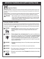
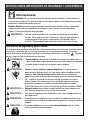
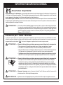
WARNING —
WARNING —
WARNING —
WARNING —
To reduce the risk of injury, do not let children use or play with pool cleaner.
WARNING —
Do not allow swimmers in the pool while pool cleaner is operating. Hose can trip or entangle
swimmers which could result in drowning.
CAUTION —
Hazardous suction. Do not play with cleaner or hose or apply to body. Can trap and
tear hair or body parts. Hose can trip or entangle swimmers which could result in
drowning.
Suction entrapment, injury, and drowning hazard. If your pools has a dedicated suction
port (”vac port”) for vacuuming or for an automatic pool cleaner, it must be covered when
not in use. A spring loaded safety cover (a “vac port fitting”) is included with your cleaner.
Install it on the suction port to prevent entrapment and injury. If the cover does not fit,
purchase one that dose from your local pool store and install it instead. The cover should
conform to IAPMO SPS-99A.
Stop pump before attempting to clean unit. Do not allow swimmers in pool while cleaner
is operating.
Moving parts may injure hands or fingers. Stop pump before attempting to clean out pool
cleaner head.
LEGEND
®
INSTALLATION MANUAL
Important Notice:
Attention Installer:
This guide contains important information about the installation, operation and safe use of
this product. This information should be given to the owner and/or operator of this equipment after installation of the
pool cleaner.
Attention User:
This manual contains important information that will help you in operating and maintaining this
pool cleaner. Please retain it for future reference. Consult Pentair with any questions regarding this equipment.
WARNING –
Before installing this product, read and follow all warning notices and instructions which are
included. Failure to follow safety warnings and instructions can result in severe injury, death,
or property damage. Call (800) 831-7133 [USA] or {Herentals – Belgium +32 (0) 14.25.99.11}
for additional free copies of these instructions.
Consumer Information and Safety
The Legend® pool cleaners are designed and manufactured to provide many years of safe and reliable service when
installed, operated and maintained according to the information in this manual. Throughout the manual, safety warnings
and cautions are identified by the “ “ symbol. Be sure to read and comply with all of the warnings and cautions.
[English] 3
IMPORTANT WARNING AND SAFETY INSTRUCTIONS

LEGEND
®
INSTALLATION MANUAL
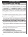
DISCLAIMER OF LIABILITY
Important Notice About Your Pool and Legend® Cleaner:
There are a multitude of factors that contribute to the life of your pool. The Legend® automatic pool cleaner
is a very passive product that will have no impact on pool life.
Please be aware that over time, deterioration, discoloration and brittleness of any pool finish can be caused
separately by, or in combination with, age, an imbalance in pool water chemistry, improper installation and
other factors. An automatic pool cleaner, such as the Legend®, will not remove or cause wear on “good” pool
plaster. In fact, the opposite is true—pool plaster will eventually cause wear on the cleaner.
The same situation holds true for vinyl-lined inground swimming pools, because vinyl liners are also
affected by the environment and factors such as pool water chemistry, sunlight and the pool’s surroundings.
Therefore over time, vinyl can become brittle and weak. In addition, vinyl-lined pools are affected by the
workmanship, composition and installation of the liner and the workmanship and quality of construction of
the supporting walls and pool base. These are all factors which can contribute to liner failure. The existence
of any of these type of conditions in your pool is not caused by the use or operation of the Legend® cleaner.
Pre-installation Check List
Before installing your cleaner, review and understand all warnings and safety information in this guide.
Failure to follow these instructions or improper installation of the cleaner can result in damage to the pool
finish or the vinyl liner, Pentair Water Pool and Spa, Inc. disclaims any liability for repairs or replacement to
any of these structures or components of the customer’s pool.
Before installing the cleaner in a vinyl liner pool:
Before installing the pool cleaner, examine the interior of your pool carefully. Check liner closely for signs of deterioration or damage from
age, chemicals, pool wall damage, etc. If any damage is found, have a qualified pool professional make all the necessary repairs. Also,
if your vinyl liner is brittle or has stones, wrinkles, roots or metal corrosion in contact with the underside of the liner, or has damage to
the base or supporting walls, do not install the pool cleaner before having a qualified professional perform the necessary repairs.
Before installing the cleaner in a gunite pool or a pool that is partially or completely tiled:
Before installing the pool cleaner in a gunite pool or pool that is partially or completely tiled; check closely for loose tiles and loose light
fittings. Do not install the pool cleaner before having a qualified professional perform the necessary repairs.
Before installing the cleaner, clean your filter system:
Make sure you have cleaned the filter, including backwashing, rinsing, and emptying all baskets. A clean system is necessary for proper
cleaner operation and coverage.
Before installing the cleaner, fill the hose with water:
Always make sure the cleaner head is submerged and the hose is full of water before connecting the hose to the filtration system
(whether through a skimmer or dedicated wall fitting). Air in the system can damage the pump through dry running and overheating.
Before installing the cleaner, understand cleaner coverage:
The cleaner is designed to rid your pool of debris in approximately 4-6 hours. Less time could be needed, depending on the pool size.
The cleaner was not designed to automatically clean steps or swimouts or to work under a solar cover. It was also not designed to do
initial cleanup for a new pool or when opening your pool for the season.
AFTER installing the cleaner, make sure the cleaner is operating correctly:
The cleaner may need some minor adjustments to make sure it is operating properly so there is no damage to the pool finish. Certain
vinyl liner patterns are particularly susceptible to surface wear, pattern removal, ink rubbing off of, or serious scratches to the pattern
caused by objects coming into contact with the vinyl surface, including automatic pool cleaners. Pentair Water Pool and Spa, Inc. is
not responsible for any pattern removal, abrasions or markings on vinyl liners.
4 [English]

LEGEND
®
INSTALLATION MANUAL
Important Information:
The Legend® automatic pool cleaner comes ready to connect into a female threaded 1-1/2" (38mm) line,
dedicated to our Universal Booster Pump. Also, if you have a chlorinator, solar system or other air
inducing equipment, please contact our Technical Support Department at 1-800-831-7133 [USA] or
{Herentals – Belgium +32 (0) 14.25.99.11}, before you install the Legend®. (See diagram on Page 8.)
The following are important facts to remember before installing and operating the Legend
®
.
1. Always disconnect the Legend® from the pool wall when cleaning or back washing the pool filter.
2. After cleaning or back washing, let the filtration system run for at least five minutes before
reconnecting the Legend®.
3. New plumbing lines should be flushed out before installing the Legend®.
4. The Legend® should not be used to remove plaster dust in new pools.
5. Always remove the Legend® before swimmers enter the pool.
6. Always handle the Legend® with care. Do not let children or pets play with the unit: it is not a toy.
7. Always pick up the Legend® by the handle, especially when lifting the unit out of the water.
8. Unless checking the wheel RPM, do not handle the Legend® while it is operating.
9. Always remove the Legend® from the pool before chemical shock treatments. As a rule, any pool
water that is unsafe for swimming is unsafe for the Legend®.
10. Carefully cut the feed hose following the instructions on Page 9.
By following these simple guidelines, you can help protect against injury and prolong the life
of your Legend
®
.
Before the Legend® is installed, please take a moment to record the serial number. This number is
located on your warranty card and on the back of the Legend® near the rear jet. You will be asked for
this number when you contact our Technical Support Department.
SERIAL #__________________________________
LL505G
LL505GG
[English] 5

LEGEND
®
INSTALLATION MANUAL
TABLE OF CONTENTS
Important Warning and Safety Instructions ....................................................................................... 3
Disclaimer of Liability ......................................................................................................................... 4
Important Information ......................................................................................................................... 5
I. Introduction ................................................................................................................................... 7
A. Thank You for Choosing the Legend®....................................................................................... 7
B. What to Expect from the Legend®............................................................................................. 7
II. Installation Instructions ................................................................................................................. 8
A. Legend® Components ............................................................................................................... 8
B. Pool Connections ..................................................................................................................... 8
C. Booster Pump Installation ........................................................................................................ 8
D. Installing the Twist Lock Pressure Relief Valve (Wall Fitting) ..................................................... 9
E. Cutting the Feed Hose .............................................................................................................. 9
F. Checking Operation ................................................................................................................ 13
G. Fine Tuning the Legend®......................................................................................................... 13
1. Thrust Jet Adjustment ....................................................................................................... 13
2. Sweep Hose Adjustment ................................................................................................... 13
3. Checking Wheel RPM ........................................................................................................ 14
III.Operation & Periodic Maintenance ............................................................................................... 14
A. Connecting/Disconnecting the Legend®.................................................................................. 14
B. Turning the Legend® On/Off .................................................................................................... 14
C. Cleaning the Sand & Silt Bag ................................................................................................. 15
D. Periodic Maintenance ............................................................................................................. 15
1. Wall Fitting Screen ............................................................................................................ 15
2. Tires & Bearings ................................................................................................................ 16
3. Roller Rings ....................................................................................................................... 16
4. Debris Bags ....................................................................................................................... 16
5. Sweep Hose ...................................................................................................................... 16
6. Debris Valve ...................................................................................................................... 16
E. Back Washing the Pool Filter ..................................................................................................16
F. Storage and Winterizing .......................................................................................................... 16
G. Accessories ........................................................................................................................... 17
1. Sweep Hose Weight........................................................................................................... 17
2. Leaf Bag ............................................................................................................................ 17
3. Suction Cup Tires .............................................................................................................. 17
IV. Troubleshooting ........................................................................................................................... 18
Legend® Parts List ...................................................................................................................... 19
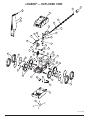
Legend® Exploded View............................................................................................................... 21
6 [English]

LEGEND
®
INSTALLATION MANUAL
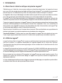
I. Introduction
A. Thank You for Choosing the Legend® Pool Cleaner
Congratulations on the purchase of your new automatic pool cleaner. The Legend® is designed to give
you years of dependable and efficient service. With the Legend®, you and your family will spend more
time relaxing and enjoying your pool and less time cleaning it.
The Legend® has been designed and built with time proven features and innovations to create
an automatic pool cleaner that will give you years of dependable service. The Legend® is built with pride
by people who care about the product using state of the art materials and backed by a limited warranty
that protects against defects in parts and construction.
Like any mechanical device, the Legend® requires some preventative maintenance and the replacement
of certain hard working parts. We recommend that you have your Legend® checked annually. For best
results have your Legend® installed by a qualified swimming pool professional.
For pool owners with plumbing and mechanical experience, installation instructions are included in this
manual.
Please put safety first!
Be sure to take your Legend® out of your pool and store it carefully in a shaded
area before anyone enters the pool.
B. What to Expect from the Legend®
When operating correctly, the Legend® will travel randomly throughout the pool, vacuuming and sweeping
the bottom. The climbing ability of the Legend® is dependent on the pools shape. It will climb better in
pools without sharp angles or curves in the transition from the pool floor to the pool wall.
The Legend® comes equipped with a Wall Fitting (Part# EW22/LLW22PM) that features a Twist Lock
Automatic Pressure Relief Valve. If the Legend® is receiving too much water pressure to the unit, the
relief valve can be manually adjusted to reduce water pressure.
Approximately every three minutes and 30 seconds the Legend® will go into a back up mode. At this
time the Back Up Valve will pull the Legend® away from it’s current location increasing it’s random
pattern.
The Sweep Hose operates in a gentle sweeping motion to prevent debris from becoming trapped in
hard to reach corners of the pool.
[English] 7

LEGEND
®
INSTALLATION MANUAL
II.Installation Instructions
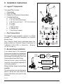
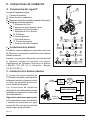
A. Legend® Components
The Legend® Box Contains:
1. Cleaner Head
2. Sand & Silt Bag
3. Sweep Hose (Attached to Cleaner Head)
4. Complete Feed Hose
a. 1 - 8½” (22 cm) hose
b. 2 - 10’ (3 m) white (hard) hoses
c. 1 - 30” (75 cm) soft hose / 1 - 7.5’ (2,3 m) soft hose
d. 10 - Floats
e. 4 - Swivels
f. 1 - Back-up Valve
g. 12 - Mender Nuts
h. 1 - Wall Fitting Complete
5.
Pool Connections
The Legend® comes equipped to connect to a female
threaded 1-1/2" (38mm) line, dedicated to our Universal
Booster Pump.
Also, if the pool doesn't have a dedicated cleaner line,
please contact our Technical Support Department at
1-800-831-7133 [USA] or {Herentals – Belgium
+32 (0) 14.25.99.11}.
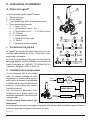
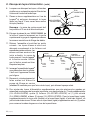
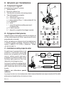
C. Booster Pump Installation
If you already have a 3/4 horsepower
booster pump installed at your equipment
pad and it is operational, skip this section
and proceed to Installing the Twist Lock
Pressure Relief Valve (Wall Fitting).
Detailed booster pump installation
instructions are packaged separately in
our booster pump box.
Please follow these instructions
carefully.
The booster pump is not self-priming and
needs to be fed with water taken from
the pool filter before any type of in-line
chlorinator.
C D G
B G C
BDEB
A E D B
H
DF
2
3
8 [English]
1
FROM
POOL FILTER
PUMP POOL
FILTER HEATER
SOLAR
SYSTEM
CHLORINATOR
TO
POOL
BOOSTER PUMP

LEGEND
®
INSTALLATION MANUAL
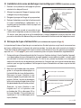
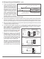
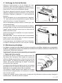
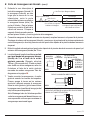
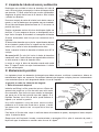
D. Installing the Twist Lock Pressure Relief Valve (Wall Fitting)
1. Take out any existing pool cleaner and/or wall
fitting.
2. Turn on the filtration pump and booster pump,
flush out the plumbing line.
3. Turn off filter pump and booster pump.
4. Remove the Wall Adapter from the Wall Fitting
and screw Adapter by hand into the dedicated
line. Turn until tight.
5. Take the Wall Fitting and Twist Lock the Wall
Fitting into the Wall Adapter 1/4 turn and pull
out; to a snug fit. Once the Wall Adapter is secure,
you can now twist lock and unlock to remove
Wall Fitting with ease from the Wall Adapter.
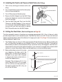
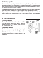
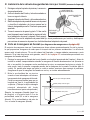
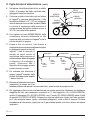
E. Cutting the Feed Hose (See Hose Diagrams on Page 10)
The Hose assembly comes in 5 sections now covering approximately 30 ft. (9 m) of the pool, which
provides ample hose for most residential pools. The Back-Up Valve is now 30" (75 cm) from the head
cleaner and should always remain this distance. For larger pools, see #14 on Page 12 for instructions on
Adding Additional Feeder Hose
.
1. Take Feeder Hose out of box (it will be approximately 30 feet [9 meters] long). Before installing the
unit, you should lay the feed hose out straight in the sun, (for one day if possible). The hose has
been curled up in the box and sometimes will go around in a circle. If this happens, take the first or
second section of hose from the wall and reverse it, (turn it around). You might have to reverse both
sections to correct the problem. Make sure the feed hose is cut and installed properly.
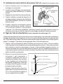
2. Measure how deep your pool is by using
your telepole or the clear end of the
feeder hose. Cut the soft hose equal to
the depth of your pool. (Hint: the grate
or domed main drain at the bottom is
usually the deepest point.)
Example:
The soft hose is 10 ft. (3 m)
long, if the pool is 8½ ft. (2,5 m) deep,
cut 1½ ft. (0,5 m) off of the soft hose. If
the depth is greater than 10 ft. (3 m), do
not cut the soft hose.
Deepest End of Pool
Telepole / Soft Hose
Measure and Mark the Water Level
Main Drain
WALL ADAPTER
INSTALLED
QUICK
LOCK
PEG
QUICK DISCONNECT
O-RING
[English] 9

LEGEND
®
INSTALLATION MANUAL
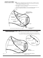
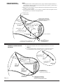
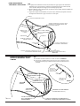
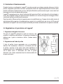
7½ FT. (2,3 M.)
EXAMPLE DIMENSION
(Your Measurement May Differ)
NOT TO SCALE
MARKED SWIVEL
FARTHEST POINT OF POOL PERIMETER FROM WALL FITTING
STEPS
1. With the feed hose assembly attached to the pool wall, hold the feed hose assembly by the opposite
end with the soft hose and walk the perimeter of the pool to locate the farthest point on the perimeter
from the wall fitting without stretching the hose assembly.
2. Measure the distance that the hose assembly extends beyond the pool perimeter farthest point
located in Step 1 — (7½ ft. [2,3 m] in this example).
3. Cut half of the length obtained from Step 2 — (3¾ ft. [1 m.] in this example), equally from each of the
10 foot (3 meters) lengths of white or grey hose on either side of the marked swivel.
10 FOOT (3 METER)
WHITE OR GREY
HOSE SECTION
10 FOOT (3 METER)
WHITE OR GREY
HOSE SECTION
10 FOOT (3 METER)
SOFT HOSE
BACK UP
VALVE
REMOVE EXCESS MATERIAL
FROM HOSE ON EITHER SIDE OF
MARKED SWIVEL AS DESCRIBED
IN STEPS 2 AND 3.
WALL FITTING
SWIVEL
SWIVEL
FLOATS
FLOATS
FLOATS
EXAMPLE OF HOSE ASSEMBLY
BEFORE CUTTING TO LENGTH
EXAMPLE OF FINISHED HOSE ASSEMBLY
AFTER CUTTING TO LENGTH
WHITE OR GREY
HARD HOSE SECTION
MARKED SWIVEL
END OF
SOFT HOSE
(End remains 30 in. [75 cm])
SOFT HOSE
(Cut to your pool depth)
BACK UP VALVE FURTHEST POINT OF POOL PERIMETER
FROM WALL FITTING
STEPS
4. Reassemble the hoses using the supplied mender nuts as shown in FIGURE 1.
5. Your complete finished hose assembly should look like this. The end of the 30 inch
(75 cm) soft hose should reach just to the furthest edge of the pool perimeter as shown.
WHITE OR GREY
HARD HOSE SECTION
FIGURE 1
WHITE OR GREY
HARD HOSE SECTION
(WALL FITTING SIDE)
WHITE OR GREY
HARD HOSE SECTION
(CLEANER SIDE)
MARKED SWIVEL
10 [English]

LEGEND
®
INSTALLATION MANUAL
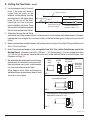
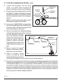
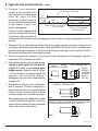
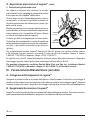
E. Cutting the Feed Hose - (cont.)
3. Lay the telepole next to the soft
hose. If the clear soft hose is
longer than the mark on the
telepole, cut the excess from the
end attached to the white (hard)
hose. Do not cut off the float.
Leave the first float in position
next to the Back-Up Valve. Place
the second float midway between
the first float and the Hose Swivel.
4. Attach feed hose to the wall fitting
and attach wall fitting to the pool wall. Hold the end of soft hose and walk the perimeter of the pool
keeping the hose straight (do not stretch hose) to find the farthest point of the pool from the wall
fitting.
5. Measure the excess length between the farthest point of the pool from Wall Fitting and the end of
30 in. (75 cm) soft hose.
6. Half of this measured length is to be cut equally from 10 ft. (3 m.) white (hard) hoses next to the
Marked Swivel. (
Example:
Half of 6 ft. [180 cm] = 3 ft. [90 cm] each). If you are cutting more than
2 ft. (60 cm) off the hoses, remove the floats next to the Marked Swivel from both hoses. See
Diagrams on Page 10.
7. Re-assemble the hoses and the swivel using
mender nuts. Put mender nut on swivels first,
then push hose over swivel, rotate mender
nut over hose clockwise until tight.
Note: Keep as many floats as possible on
white feed hoses spaced evenly apart to hold
hose up on top of water.
Water Level
White (Hard) Hoses Swivel
Cut and Remove the
Excess Hose Length Cut Soft Hose Equal to the
Deepest Pool Water Level
Telepole / Soft Hose
FEED
HOSE
MENDER
NUT
BARB ON SWIVEL
OR LEGEND
STEP 1
STEP 2
STEP 3
PUSH HOSE OVER BARB
PUSH MENDER NUT TOWARD HOSE AND ROTATE
CLOCKWISE BY HAND UNTIL TIGHT
SMALL END
OF MENDER
NUT AWAY
FROM HOSE
[English] 11

LEGEND
®
INSTALLATION MANUAL
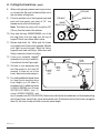
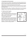
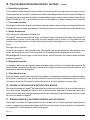
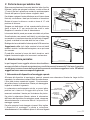
E. Cutting the Feed Hose - (cont.)
8. When cutting hoses, please use strong scissors
or a sharp knife. Be sure to slide the floats out of
the way when cutting hose.
9. Put extra mender nut on the Legend® mast and
push soft hose gently over mast at 1/2", turn
mender nut around soft hose tight.
Note: The Back-Up Valve still should be 30"
(76 cm) from the head of the cleaner.
10. Now take the bag, 360002/360009, out of the
box and firmly twist lock bag onto the top of
Legend® throat over rubber debris valve.
11. Review and check list: White and soft hoses
cut properly and floats evenly spaced. Mender
nuts tight around swivels, Back-Up Valve,
Legend® mast and wall fitting. Make sure wall
fitting is securely locked into place.
12. Lower your complete Legend®
assembly into your pool carefully.
It should look like the Figure-right.
13. Go back to your equipment and
turn filter pump on first (wait 30
seconds to force air out of the
hose), then turn booster pump on.
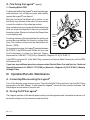
14. For adding additional feeder hose
for large pools requiring more
hose length you will need to
purchase one (1) additional hose
(LLD45/LLD45PM), four (4) floats
(ED10P/LLD10PM), one (1)
swivel (ED05/LLD05PM), and
two (2) mender nuts (ED15/LLD15PM). Attach extra white (hard) hose between soft hose and existing
white (hard) hose, using floats, swivel and mender nuts. Divide extra white (hard) hose overage by
three (3) this time to keep all white hoses the same length.
FEED HOSE
MENDER NUT
FEED MAST
RUBBER
DEBRIS VALVE
FIRST
SWIVEL SECOND
SWIVEL THIRD
SWIVEL
SHORT
WHITE
HOSE
LONG
WHITE
HOSE
LONG
WHITE
HOSE BACK UP
VALVE
SOFT
HOSE
12 [English]

LEGEND
®
INSTALLATION MANUAL
F. Checking Operation
When operating correctly, the Legend® will travel in a random pattern throughout the pool, vacuuming
and sweeping the bottom. The climbing ability of the Legend® is dependent on the pools structure and
water flow coming into the pool. It will perform more efficiently in pools without sharp angles or curves in
the transition from the floor of the pool to the wall.
The Legend® comes with a Twist Lock Pressure Relief Valve (Wall Fitting). If the Legend® is receiving too
much water pressure, the Relief Valve in the Wall Fitting will release the excess water pressure.
Approximately every three minutes and 30 seconds the Legend® will go into a back-up mode. The
Back-Up Valve cycle time, while in the back-up mode, is approximately 30 seconds, pulling the Legend®
from it’s current location increasing it’s random pattern.
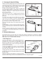
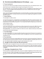
G. Fine Tuning the Legend
®
1. Thrust Jet Adjustment
There is a Thrust Jet located in the back of the Legend®. This
Thrust Jet alters the direction of the cleaner. The factory
standard position for the jet is set in the middle and straight
out. (See illustration – right.)
2. Sweep Hose Adjustment
The Sweep Hose operates in a gentle sweeping motion. To
increase or decrease the motion of the Sweep Hose, adjust
the screw which is located on the Feed Mast Barb below the
Ballast Float. Turning the screw clockwise will decrease the
motion and counter-clockwise to increase the motion of the
Sweep Hose.
[English] 13

LEGEND
®
INSTALLATION MANUAL
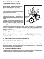
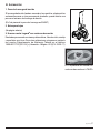
G. Fine Tuning the Legend® - (cont.)
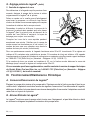
3. Checking Wheel RPM
To determine whether the Legend® is receiving the proper
water pressure, turn off the pool pump, and carefully
remove the Legend® from the pool.
Mark the front drive Tire/Wheel with a marker, or use
the Pentair logo located on the side of tire as a marker
to count the rotations of the wheel per minute.
Have someone turn on pool pump and the booster pump
while you place the Legend® in the pool just beneath
the water surface. (Be sure to hold onto the Sweep Hose
to avoid getting wet).
Count the rotations of the marked wheel for exactly one
minute. (Be sure the Back-Up Valve isn't cycling at this
time). The rotations will give you the Revolutions Per
Minute – (RPM).
For proper performance, the Legend® operates between
28-32 RPM. If the RPM is below 28 then call your local
Pool Professional or contact our Technical Support
Department at 1-800-831-7133 [USA] or {Herentals – Belgium +32 (0) 14.25.99.11}.
If the RPM is more than 32, at the Wall Fitting, unscrew the Pressure Relief Valve slowly until the RPM
falls between 28-32.
If you have any additional questions, please contact Pentair Water Pool and Spa, Inc., Technical
Support Department at:1-800-831-7133 [USA] or {Herentals – Belgium +32 (0) 14.25.99.11}, Monday
through Friday.
III. Operation/Periodic Maintenance
A. Connecting/Disconnecting the Legend®
Turn off the booster pump and pool pump. Then take the Wall Fitting and twist lock the Wall Fitting
clockwise into the Wall Adapter. To disconnect the Legend®, unlock and twist counter-clockwise. The
Wall Adapter should remain in the pool wall.
B. Turning On/Off the Legend®
The Legend® operates off the booster pump coming from the equipment pad, and can be turned on or off
by merely turning on/off your booster pump time clock.
SWEEP
HOSE
FRONT
WHEEL
DRIVE
14 [English]

LEGEND
®
INSTALLATION MANUAL
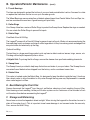
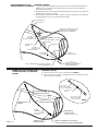
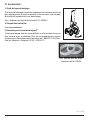
C. Cleaning the Sand & Silt Bag
Carefully unlock the debris bag from the vacuum tube. Use
your thumb to push the "U" shaped snap lock closure upward
until it snaps open. Make sure to swing it away from the
opening. Open the bag and remove debris.
To close, push the middle of bag inward, as shown, and
bring the edges together to make them stack like an
accordion. Swing the "U" shaped snap lock closure back
to the closing position.
Gently push on top of the "U" shaped snap lock closure to
make sure it snaps into place. Reattach the clip onto the
feed hose.
Your debris bag is ready to be reinstalled onto your cleaner.
If you have a lot of debris in your pool, especially after a
storm, you can run your Legend® in two shorter cycles per
day and empty the debris bag between cycles.
Reconnect the debris bag to the vacuum tube. Do NOT
over turn.
A Helpful Hint:
It is easier to empty the debris bag when it
is dry. A second bag may be used while the full debris bag
is drying.
It's best to empty the debris bag when it becomes half full.
The Legend® will have better performance if the bag is not
overloaded.
D. Periodic Maintenance
The following parts are wear items that should be checked, maintained or replaced as needed.
Wear items are considered any working or moving part(s) being worn due to the use of the cleaner.
Wear items are not covered under warranty.
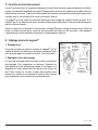
1. Wall Fitting Screen
Inside the wall fitting is a filter screen that acts as a
secondary filter. This screen is to keep debris that is
passed by the pool filter out of the Legend®.
Running the
Cleaner without the filter screen can damage the Legend
®
and will void the warranty.
A continuous plugged or dirty screen is a sign of problems
in your pool filtration system and you need to contact
your local Pool Professional.
To clean the filter screen, pull the screen out from inside
the Wall Fitting and rinse thoroughly and push back inside
the Wall Fitting.
Whenever cleaning, back-washing or repairing the filter,
remove the Wall Fitting and flush out the dedicated line before using the Legend®.
"U" SHAPED SNAP LOCK
CLOSURE
CLIP
PUSH DOWN TO
SNAP TOGETHER
CLEANER BAG
OPEN OPEN
Push middle of
the bag inward
for closure.
OPEN
CLOSE
CLEANER BAG
"U" SHAPED
SNAP LOCK
CLOSURE
OPEN OPEN
[English] 15

LEGEND
®
INSTALLATION MANUAL
III. Operation/Periodic Maintenance - (cont.)
2. Tires & Bearings
The tires are designed to protect the bottom of your pool and provide better traction. You need to rotate
or replace the tires when the tire is worn up to the wear groove.
The Wheel Bearings are warranted free of defects when shipped from Pentair Water Pool and Spa, Inc.,
and are considered a wear item. A good bearing will spin freely.
3. Roller Rings
Your Sweep Hose has a series of Roller Rings to protect the Sweep Hose. Replace the rings as needed.
You can rotate the Roller Rings to prevent flat spots.
4. Debris Bags
Fine Mesh Sand & Silt Bag
The Legend® comes with a Sand & Silt bag for general use in all pools. We do not recommend using the
fine mesh bag to pick up leaves and twigs or other large debris for they have sharp points and edges that
can poke holes and eventually rip the bag.
Optional Leaf Bag
The leaf bag is a larger mesh bag made to pick up heavier debris such as leaves, twigs, acorns, etc.
This bag can be helpful especially after a storm.
A Helpful Hint:
To prolong the life of bags, remove the cleaner from pool before adding chemicals.
5. Sweep Hose
The Sweep Hose is provided to help keep the bottom and sides of your pool clean. The Sweep Hose is
warranted free of defects when shipped from the factory, and is considered a wear item.
6. Debris Valve
This valve is located under the Debris Bag, it is designed to keep the debris inside the bag. It functions
like a check valve to allow the debris to only enter through the bag one way. Replacement is needed
when valve begins to stiffen.
E. Back Washing the Pool Filter
Always disconnect the Legend® from the pool wall before cleaning or back washing the pool filter.
After cleaning or back washing, let the pool filtration system run for a minimum of five minutes to flush
out the return lines before reconnecting the Legend®.
F. Storage and Winterizing
Never leave or store the Legend® in direct sunlight. When storing the Legend® for the winter, be sure to
drain all the water from it. This is important since freeze damage is not covered under the warranty.
Also, remove the Wall Fitting.
16 [English]

LEGEND
®
INSTALLATION MANUAL
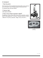
G. Accessories
1. Sweep Hose Weight
If the sweep hose tends to break the surface of the water therefore
squirting nearby windows or innocent bystanders, a weight can be installed
to the end of the sweep hose.
(Part # for Hose Weight is EH09C)
2. Leaf Bag
(See previous page)
3. New Legend® Suction Cup Tires
Designed to climb in problem areas, fiberglass, tile and smooth surfaces.
For other applications, please contact our Technical Service Department
at 1-800-831-7133 [USA] or {Herentals – Belgium +32 (0) 14.25.99.11}.
Part # for Suction Cup Tires
is: LC6LSA
[English] 17

LEGEND
®
INSTALLATION MANUAL
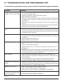
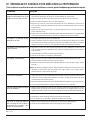
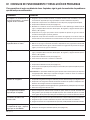
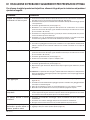
To insure the best performance from your cleaner, follow the troubleshooting guide listed below.
IV. TROUBLESHOOTING AND PERFORMANCE TIPS
Problem
Legend® doesn't move or moves
sluggishly or hangs up on steps.
Legend® falling over or lying on its
side.
Legend® will not back up.
Legend® will not climb.
Hoses tangling.
Sweep Hose is sucked into the
cleaner.
Booster Pump very noisy.
Sweep Hose breaks water surface
and sprays nearby windows, patio
decks and bystanders.
Solution
1. Be sure filter pump and booster pump are on and working properly. (You may need
to clean your pool filter system).
2. Check the Wall Fitting screen for debris and rinse clean.
3. Check wheel RPM, (see page 14).
4. Determine if the Back-Up Valve is cycling. (Hold the valve out of the water and the
jet should come on for approx. 30 seconds and shut off for approx. 3 minutes and
30 seconds.)
5. Check all the Hose connections and Swivels for leaks that can cause loss of water
pressure.
6. Check debris that may be jammed in the gear teeth on one of the front drive wheels.
Gently rotate the front wheels backward to dislodge debris.
1. This usually indicates the bag needs to be emptied.
2. Check to see if the ballast float (EA20) is leaking by checking if there is water inside.
Unscrew by pulling back while turning counter-clockwise. When it comes off, shake
it and listen for water in the float.
1. Determine if the Back-Up Valve is cycling. (Hold the valve out of the water and the
jet should come on for approx. 30 seconds, and shut off for approx. 3 minutes and
30 seconds).
2. Check the wheel RPM, (see page 14).
3. Empty the debris bag if full or half full.
1. Even if your pool doesn't show algae you still need to brush the sides of the pool
wall.
2. Check the wheel RPM, (see page 14).
3. Reposition the Thrust Jet. Loosen the two screws to adjust the Thrust Jet,
(see page 13).
A Reminder: The climbing ability of the Legend
®
is dependent on the pool's shape and
available water pressure. It will climb better in pools without sharp angles or curves
in the transition from the pool floor to the pool wall.
1. Check the length of the Feed Hose, they may be to long, (see pages 9-12).
2. Check to see that the Feed Hose is floating on top of surface. Check hose floats
for even spacing.
3. Twist the Hose Swivels to see if they spin freel and replace any that will not.
4. Lay out the Feed Hose straight in the full sun to remove any memory.
1. Adjust the Sweep Hose using the Adjustment Screw located on the bottom of the
Swivel Mast and just below the upper Thrust Jet. Turn Adjustment Screw clockwise
until the Sweep Hose is in a gentle sweeping motion.
1. Make sure Wall Fitting is mounted in pool wall correctly.
2. Make sure Pool Filtration system is working properly.
3. Contact your local Pool Professional - possible Booster Pump problem.
1. Adjust Sweep Hose to a gentle sweeping motion.
2. Add optional Sweep Hose weight, (see page 16).
18 [English]

LEGEND
®
INSTALLATION MANUAL
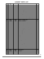
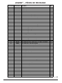
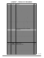
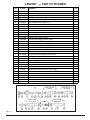
LEGEND® PARTS LIST
[English] 19
Item # International
P/N's USA P/N's Description Qty.
1 360003 360003 Top Cover 1
2 LLU145N LLU145N Main Frame 1
2 360010 360010 Main Frame – Grey 1
3 360004 360004 Bottom Cover 1
3 360011 360011 Bottom Cover – Grey 1
4 G-L-LLU6 LLU6 Feed Mast w/O-Ring – White 1
4 LLU6G LLU6G Feed Mast w/O-Ring – Grey 1
5 G-L-EC86 EC86 Turbine Drive Shaft – Complete 1
6 EC83 EC83 Turbine Spacers 2
7 G-L-EC80 EC80 Turbine Bearings 2
8 G-L-EA40 EA40 Turbine Shaft Shield 1
9 G-L-EC110 EC110 Turbine Cover w/Elbows 1
10 G-L-EC120 EC120 Turbine/Venturi Hose – 7¾" (20 cm) length 2
10 LLC120G LLC120G Turbine/Venturi Hose – 7¾" (20 cm) length – Grey 2
11 G-L-EB5L EB5L Sweep Hose – Complete 1
11 LLB5G LLB5G Sweep Hose – Complete – Grey 1
12 G-L-EB10 EB10 Sweep Hose – Wear Ring 9
13 G-L-EB25 EB25 Sweep Hose – Jet w/Collar 1
13 LLB25PM LLB25PM Sweep Hose – Jet w/Collar – Grey 1
14 370198 370198 Sweep Hose – Adjustment Screw 1
15 G-L-EA20 EA20 Ballast Float 1
15 LLA20G LLA20G Ballast Float – Grey 1
16 G-L-EH07 EH07 Sweep Hose – Hose Sleeve 4
16 LLH07PM LLH07PM Sweep Hose – Hose Sleeve – Grey 4
17 G-L-EU15 EU15 Coarse Mesh Bag – (Optional - not shown) 1
17 EU15G EU15G Coarse Mesh Bag – Grey Collar – (Optional - not shown) 1
18 360002 360002 Fine Mesh Bag – Mechanical Lock 1
18 360009 360009 Fine Mesh Bag – Grey – Mechanical Lock 1
18 G-L-EU16 EU16 Fine Mesh Bag – Velcro Brand Fastener 1
18 EU16G EU16G Fine Mesh Bag – Velcro Brand Fastener – Grey 1
19 G-L-EU9 EU9 Debris Valve 1
20 G-L-EU7 EU7 O-Ring for Feed Mast 1
21 G-L-E18 E18 O-Ring for Thrust Jet 1
22 G-L-EC130 EC130 Thrust Jet 1
23 G-L-EC135 EC135 Thrust Jet – Plate 1
23 LLC135G LLC135G Thrust Jet – Plate – Grey 1
24 G-L-EC65 EC65 Axle – Large Wheels 4
25 G-L-EC70 EC70 Axle Plate 4
26 370258Z 370258Z Axle Screw w/Lock Washer 8
27 360006 360006 Wheel w/Out Bearings 4
28 G-L-EC60 EC60 Wheel Bearings – Only 8
29 G-L-EC55 EC55 Wheel Screw Plastic 4
29 LLC55PM LLC55PM Wheel Screw Plastic – Grey 4
30 G-L-E10 E10 Back-up Valve 1
30 LL10PM LL10PM Back-up Valve – Grey 1
31 360007 360007 Wheel – Rubber Tire 4
31 360012 360012 Wheel – Grey Tire 4
32 G-L-EB15 EB15 Hose Clamp 5
33 G-L-EC40 EC40 Screw 7
34 360005 360005 Hub Cap 4
34 360013 360013 Hub Cap – Grey 4

LEGEND
®
INSTALLATION MANUAL
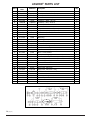
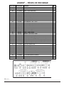
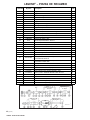
LEGEND® PARTS LIST
20 [English]
Item # International
P/N's .ytQnoitpircseDs'N/P ASU
1)m 3( '01 - tfoS – esoH deeF05DLL05DL-L-G53
1)m 3( '01 - tfoS yerG – esoH deeFMP05DLLMP05DLL53
01esoH deeF – taolFP01DEP01DE-L-G63
01yerG – esoH deeF – taolFMP01DLLMP01DLL63
2)m 3( '01 - etihW – esoH deeF54DLL54DL-L-G73
2)m 3( '01 - yerG – esoH deeFMP54DLLMP54DLL73
2esoH deeF – leviwS50DE50DE-L-G83
2yerG – esoH deeF – leviwSMP50DLLMP
50DLL83
39 G-L-LLU1 LLU1 Adapter Hose – White - 8½" (22 cm) 1
39 LLU1PM LLU1PM Adapter Hose – Grey - 8½" (22 cm) 1
40 G-L-ED15 ED15 Mender Nut – Plastic – Feed Hose 8
40 LLD15PM LLD15PM Mender Nut – Plastic – Feed Hose – Grey 8
41 G-L-EW22 EW22 Wall Fitting 1
41 LLW22PM LLW22PM Wall Fitting – Grey 1
41 E25 E25 Pressure Relief Valve – White 1
41 LL25PM LL25PM Pressure Relief Valve – Grey 1
42 G-L-E24 E24 Screen – Wall Fitting 1
43 G-L-E23 E23 Quick Disconnect Adapter 1
43 LL23PM LL23PM Quick Disconnect Adapter – Grey 1
44 G-L-EC64 EC64 Wheel – Plastic Washer 4
– G-L-EH09C EH09C Sweep Hose Weight (Optional - not shown) 1
46 G-L-EG15 EG15 Gears – for Back-Up Valve 1
47 G-L-EC131 EC131 Thrust Jet Repair Kit – Includes: EC130, EC135 and E18 1
47 360014 360014 Thrust Jet Repair Kit – Includes: EC130, LLC135 and E19 1
48 G-L-EA30 EA30 Screw for EA40 and EC110 5
49 370017 370017 Sweep Hose – Scrubber 1
50 G-L-EU147 EU147 Snap Fit Vac Tube Posts 2
50 LLU147G LLU147G Snap Fit Vac Tube Posts – Grey 2
51 G-L-EU79 EU79 Nut & Bolt – Feed Mast to Vac Tube 1
52 G-L-LLU8 LLU8 Venturi Jets 2
52 LLU8G LLU8G Venturi Jets – Grey 2
53 G-L-EU80 EU80 Screw – Top and Bottom Cover 4
54 360008 360008 Clip Hose – for 360002 1
54 360015 360015 Clip Hose – Grey – for 360009 1
SECOND 10'
HOSE
FIRST 10'
HOSE
30" SOFT
HOSE
7.5' SOFT
HOSE
35
La pagina si sta caricando...
La pagina si sta caricando...
La pagina si sta caricando...
La pagina si sta caricando...
La pagina si sta caricando...
La pagina si sta caricando...
La pagina si sta caricando...
La pagina si sta caricando...
La pagina si sta caricando...
La pagina si sta caricando...
La pagina si sta caricando...
La pagina si sta caricando...
La pagina si sta caricando...
La pagina si sta caricando...
La pagina si sta caricando...
La pagina si sta caricando...
La pagina si sta caricando...
La pagina si sta caricando...
La pagina si sta caricando...
La pagina si sta caricando...
La pagina si sta caricando...
La pagina si sta caricando...
La pagina si sta caricando...
La pagina si sta caricando...
La pagina si sta caricando...
La pagina si sta caricando...
La pagina si sta caricando...
La pagina si sta caricando...
La pagina si sta caricando...
La pagina si sta caricando...
La pagina si sta caricando...
La pagina si sta caricando...
La pagina si sta caricando...
La pagina si sta caricando...
La pagina si sta caricando...
La pagina si sta caricando...
La pagina si sta caricando...
La pagina si sta caricando...
La pagina si sta caricando...
La pagina si sta caricando...
La pagina si sta caricando...
La pagina si sta caricando...
La pagina si sta caricando...
La pagina si sta caricando...
La pagina si sta caricando...
La pagina si sta caricando...
La pagina si sta caricando...
La pagina si sta caricando...
La pagina si sta caricando...
La pagina si sta caricando...
La pagina si sta caricando...
La pagina si sta caricando...
La pagina si sta caricando...
La pagina si sta caricando...
La pagina si sta caricando...
La pagina si sta caricando...
La pagina si sta caricando...
La pagina si sta caricando...
La pagina si sta caricando...
La pagina si sta caricando...
La pagina si sta caricando...
La pagina si sta caricando...
La pagina si sta caricando...
La pagina si sta caricando...
-
 1
1
-
 2
2
-
 3
3
-
 4
4
-
 5
5
-
 6
6
-
 7
7
-
 8
8
-
 9
9
-
 10
10
-
 11
11
-
 12
12
-
 13
13
-
 14
14
-
 15
15
-
 16
16
-
 17
17
-
 18
18
-
 19
19
-
 20
20
-
 21
21
-
 22
22
-
 23
23
-
 24
24
-
 25
25
-
 26
26
-
 27
27
-
 28
28
-
 29
29
-
 30
30
-
 31
31
-
 32
32
-
 33
33
-
 34
34
-
 35
35
-
 36
36
-
 37
37
-
 38
38
-
 39
39
-
 40
40
-
 41
41
-
 42
42
-
 43
43
-
 44
44
-
 45
45
-
 46
46
-
 47
47
-
 48
48
-
 49
49
-
 50
50
-
 51
51
-
 52
52
-
 53
53
-
 54
54
-
 55
55
-
 56
56
-
 57
57
-
 58
58
-
 59
59
-
 60
60
-
 61
61
-
 62
62
-
 63
63
-
 64
64
-
 65
65
-
 66
66
-
 67
67
-
 68
68
-
 69
69
-
 70
70
-
 71
71
-
 72
72
-
 73
73
-
 74
74
-
 75
75
-
 76
76
-
 77
77
-
 78
78
-
 79
79
-
 80
80
-
 81
81
-
 82
82
-
 83
83
-
 84
84


Pentair LL505G Guida utente
- Categoria
- Accessori piscina fuori terra
- Tipo
- Guida utente
in altre lingue
- français: Pentair LL505G Mode d'emploi
- español: Pentair LL505G Guía del usuario
Documenti correlati
Altri documenti
-
Bestway S100101 Manuale utente
-
Bestway Lay-Z-Spa Manuale del proprietario
-
STA-RITE BOOST-RITE EVO Istruzioni per l'uso
-
Polaris Vac-Sweep 380 Manuale del proprietario
-
 Polaris Pools Zodiac Pool Systems - Vacuum Cleaner 180 Manuale utente
-
-
-
Polaris Vac-Sweep 280 Manuale del proprietario
-
-
