Yamaha RX-V990 Manuale utente
- Categoria
- Lettori di cassette
- Tipo
- Manuale utente

RX-V990
Natural Sound Stereo Receiver
Récepteur stéréo “Son Naturel”
OWNER’S MANUAL
MODE D’EMPLOI

2
SAFETY INSTRUCTIONS
7 Wall or Ceiling Mounting — The unit should be mounted
to a wall or ceiling only as recommended by the
manufacturer.
8 Ventilation — The unit should be situated so that its
location or position does not interfere with its proper
ventilation. For example, the unit should not be situated
on a bed, sofa, rug, or similar surface, that may block
the ventilation openings; or placed in a built-in
installation, such as a bookcase or cabinet that may
impede the flow of air through the ventilation openings.
9 Heat — The unit should be situated away from heat
sources such as radiators, stoves, or other appliances
that produce heat.
10 Power Sources — The unit should be connected to a
power supply only of the type described in the operating
instructions or as marked on the unit.
11 Power-Cord Protection — Power-supply cords should be
routed so that they are not likely to be walked on or
pinched by items placed upon or against them, paying
particular attention to cords at plugs, convenience
receptacles, and the point where they exit from the unit.
12 Cleaning — The unit should be cleaned only as
recommended by the manufacturer.
13 Nonuse Periods — The power cord of the unit should be
unplugged from the outlet when left unused for a long
period of time.
14 Object and Liquid Entry — Care should be taken so that
objects do not fall into and liquids are not spilled into the
inside of unit.
15 Damage Requiring Service — The unit should be
serviced by qualified service personnel when:
A. The power-supply cord or the plug has been damaged;
or
B. Objects have fallen, or liquid has been spilled into the
unit; or
C. The unit has been exposed to rain; or
D. The unit does not appear to operate normally or exhibits
a marked change in performance; or
E. The unit has been dropped, or the enclosure damaged.
16 Servicing — The user should not attempt service the
unit beyond those means described in the operating
instructions. All other servicing should be referred to
qualified service personnel.
17 Power Lines — An outdoor antenna should be located
away from power lines.
18 Grounding or Polarization — Precautions should be
taken so that the grounding or polarization is not
defeated.
1 Read Instructions — All the safety and operating
instructions should be read before the unit is operated.
2 Retain Instructions — The safety and operating
instructions should be retained for future reference.
3 Heed Warnings — All warnings on the unit and in the
operating instructions should be adhered to.
4 Follow Instructions — All operating and other
instructions should be followed.
5 Water and Moisture — The unit should not be used near
water – for example, near a bathtub, washbowl, kitchen
sink, laundry tub, in a wet basement, or near a
swimming pool, etc.
6 Carts and Stands — The unit should be used only with
a cart or stand that is recommended by
the manufacturer.
6A An unit and cart combination should be
moved with care. Quick stops,
excessive force, and uneven surfaces
may cause the unit and cart combination to overturn.
CAUTION: TO REDUCE THE RISK OF ELECTRIC SHOCK, DO NOT
REMOVE COVER (OR BACK). NO USER-SERVICEABLE PARTS INSIDE.
REFER SERVICING TO QUALIFIED SERVICE PERSONNEL.
CAUTION
RISK OF ELECTRIC SHOCK
DO NOT OPEN
• Explanation of Graphical Symbols
The lightning flash with arrowhead symbol, within an equilateral
triangle, is intended to alert you to the presence of uninsulated
“dangerous voltage” within the product’s enclosure that may be
of sufficient magnitude to constitute a risk of electric shock to
persons.
The exclamation point within an equilateral triangle is intended
to alert you to the presence of important operating and
maintenance (servicing) instructions in the literature
accompanying the appliance.
IMPORTANT!
Please record the serial number of this unit in the space
below.
Model:
Serial No.:
The serial number is located on the rear of the unit.
Retain this Owner’s Manual in a safe place for future
reference.
WARNING
TO REDUCE THE RISK OF FIRE OR ELECTRIC SHOCK,
DO NOT EXPOSE THIS UNIT TO RAIN OR MOISTURE.

3
FCC INFORMATION
1. IMPORTANT NOTICE: DO NOT MODIFY THIS
UNIT! This product, when installed as indicated in the
instructions contained in this manual, meets FCC
requirements. Modifications not expressly approved
by Yamaha may void your authority, granted by the
FCC, to use the product.
2.
IMPORTANT: When connecting this product to
accessories and/or another product use only high
quality shielded cables. Cable/s supplied with this
product MUST be used. Follow all installation
instructions. Failure to follow instructions could void
your FCC authorization to use this product in the USA.
3. NOTE: This product has been tested and found to
comply with the requirements listed in FCC
Regulations, Part 15 for Class “B” digital devices.
Compliance with these requirements provides a
reasonable level of assurance that your use of this
product in a residential environment will not result in
harmful interference with other electronic devices.
This equipment generates/uses radio frequencies
and, if not installed and used according to the
instructions found in the users manual, may cause
interference harmful to the operation of other
electronic devices.
Compliance with FCC regulations does not guarantee
that interference will not occur in all installations. If
this product is found to be the source of interference,
which can be determined by turning the unit “OFF”
and “ON”, please try to eliminate the problem by using
one of the following measures:
Relocate either this product or the device that is being
affected by the interference.
Utilize power outlets that are on different branch
(circuit breaker of fuse) circuits or install AC line filter/s.
In the case of radio or TV interference, relocate/
reorient the antenna. If the antenna lead-in is 300
ohm ribbon lead, change the lead-in to coaxial type
cable.
If these corrective measures do not produce
satisfactory results, please contact the local retailer
authorized to distribute this type of product. If you can
not locate the appropriate retailer, please contact
Yamaha Electronics Corp., U.S.A. 6600 Orangethorpe
Ave, Buena Park, CA 90620
The above statement apply ONLY to those products
distributed by Yamaha Corporation of America or its
subsidiaries.
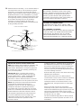
19 Outdoor Antenna Grounding — If an outside antenna is
connected to this unit, be sure the antenna system is
grounded so as to provide some protection against
voltage surges and built-up static charges. Article 810 of
the National Electrical Code, ANSI/NFPA 70, provides
information with regard to proper grounding of the mast
and supporting structure, grounding of the lead-in wire
to an antenna discharge unit, size of grounding
conductors, location of antenna discharge unit,
connection to grounding electrodes, and requirements
for the grounding electrode.
ANTENNA
DISCHARGE UNIT
(NEC SECTION 810-20)
GROUNDING CONDUCTORS
(NEC SECTION 810-21)
GROUND CLAMPS
POWER SERIVCE GROUNDING
ELECTRODE SYSTEM
(NEC ART 250, PART H)
NEC – NATIONAL ELECTRICAL CODE
ELECTRIC
SERVICE
EQUIPMENT
GROUND
CLAMP
MAST
ANTENNA
LEAD IN
WIRE
EXAMPLE OF ANTENNA GROUNDING
Note to CATV system installer:
This reminder is provided to call the CATV system
installer’s attention to Article 820-40 of the NEC that
provides guidelines for proper grounding and, in
particular, specifies that the cable ground shall be
connected to the grounding system of the building, as
close to the point of cable entry as practical.
CAUTION (FOR CANADA MODEL)
TO PREVENT ELECTRIC SHOCK, MATHC WIDE
BLADE OF PLUG TO WIDE SLOT AND FULLY INSERT.
FOR CANADIAN CUSTOMERS
THIS DIGITAL APPARATUS DOES NOT EXCEED THE
“CLASS B” LIMITS FOR RADIO NOISE EMISSIONS
FROM DIGITAL APPARATUS SET OUT IN THE
RADIO INTERFERENCE REGULATIONS OF THE
CANADIAN DEPARTMENT OF COMMUNICATIONS.

4
CAUTION: READ THIS BEFORE OPERATING YOUR UNIT
1 To ensure the finest performance, please read this
manual carefully. Keep it in a safe place for future
reference.
2 Install your unit in a cool, dry, clean place – away from
windows, heat sources, and too much vibration, dust,
moisture or cold. Avoid sources of hum (transformers,
motors). To prevent fire or electrical shock, do not
expose to rain and water.
3 Do not operate the unit upside-down. It may overheat,
possibly causing damage.
4 Never open the cabinet. If a foreign object drops into
the set, contact your dealer.
5 Do not use force on switches, knobs or cords. When
moving the set, first turn the unit off. Then gently
disconnect the power plug and the cords connecting to
other equipment. Never pull the cord itself.
6 Do not attempt to clean the unit with chemical solvents;
this might damage the finish. Use a clean, dry cloth.
7 Always set the volume control to “–
∞
” before starting
the audio source play: increase the volume gradually to
an appropriate level after the play is started.
8 To prevent lightning damage, pull out the power cord
and remove the antenna cable during an electrical
storm.
9 Be sure to read the “Troubleshooting” section on
common operating errors before concluding that your
unit is faulty.
10 Do not connect audio equipment to the AC outlets on
the rear panel if that equipment requires more power
than the outlets are rated to provide.
11 When not planning to use this unit for long periods of
time (ie., vacation, etc.), disconnect the AC power plug
from the wall outlet.
The apparatus is not disconnected from the AC power
source as long as it is connected to the wall outlet, even
if the apparatus itself is turned off.
We Want You Listening For A Lifetime
YAMAHA and the Electronic Industries Association’s
Consumer Electronics Group want you to get the most out
of your equipment by playing it at a safe level. One that lets
the sound come through loud and clear without annoying
blaring or distortion – and, most importantly, without
affecting your sensitive hearing. Since hearing damage from
loud sounds is often undetectable until it is too
late, YAMAHA and the Electronic Industries
Association’s Consumer Electronics Group
recommend you to avoid prolonged exposure
from excessive volume levels.
Contents
PROFILE OF THIS UNIT....................................................7
SPEAKER SETUP FOR THIS UNIT...................................8
CONTROLS AND FUNCTIONS .......................................10
CONNECTIONS ...............................................................12
ADJUSTMENT BEFORE OPERATION............................18
BASIC OPERATIONS ......................................................21
TUNING OPERATIONS ...................................................24
USING THE DIGITAL SOUND FIELD
PROCESSOR (DSP) ........................................................28
SETTING THE SLEEP TIMER .........................................33
REMOTE CONTROL TRANSMITTER .............................34

5
ENGLISH
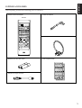
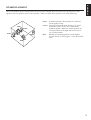
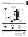
SUPPLIED ACCESSORIES
After unpacking, check that the following parts are contained.
• Remote Control Transmitter • Indoor FM Antenna
• Batteries (size AA, LR6, UM-3)
• Adapter for F-type connector
• User Program Sheets
• AM Loop Antenna
Remote
+
POWER
PLAY
TAPE 1
DIR A DIR B
SKIP
PHONO
CD
TUNER
STOP
VCR 1
VCR 2
STOP PLAY
V–AUX
SLEEP TV VCR AUX
DISC
SKIP
SEARCH
SEARCH
SEARCH
PAUSE/STOP
PAUSE/STOP
DECK
A/B
PRESET
—
REC/PAUSEREC MUTE TAPE 2 MON
PLAY LD/TV
CHAPTER/CH
—
+
DISPLAY
MASTER
VOLUME
—
+
TEST
MUTING
+
+
+
—
—
—
TRANSMIT
/LEARN
DSP
HALL
EFFECT
CHURCH
CENTER LEVEL
REAR LEVEL
DELAY
TIME
MOVIE THEATER
JAZZ CLUB
STADIUM
PRO LOGIC
SURROUND
SPORTS
ENHANCED
ROCK
THEATER
70mm TV
YPC LEARN
USER
1234
5678
910
ON/OFF
RESET CLEAR
A B C D E

6
Features
• Five Speaker Configuration
Front: 100 W + 100 W (8Ω) RMS Output Power,
0.015% THD, 20-20,000 Hz
120 W + 120 W (6Ω) RMS Output Power,
0.04% THD, 20-20,000 Hz (USA Model Only)
Center: 100 W (8Ω) RMS Output Power,
0.015% THD, 1 kHz
Rear: 25 W + 25 W (8Ω) RMS Output Power,
0.08% THD, 1 kHz
• Digital Sound Field Processor
10 Programs including “Cinema DSP” 70mm Movie Theater
• 5 Channel Discrete Input for Dolby Surround Digital AC-3
• Automatic Input Balance Control for Dolby Pro Logic Surround
• Test Tone Generator for Easier Speaker Output Balance Adjustment
• 3 Center Channel Modes (NORMAL/WIDE/PHANTOM)
• 40-Station Random Access Preset Tuning
• Automatic Preset Tuning (FM only)
• Preset Station Shifting Capability (Preset Editing)
• IF Count Direct PLL Synthesizer Tuning System
• Video Signal Input/Output Capability
• SLEEP Timer
• Remote Control Capability
• Program and status messages superimposed on connected video monitor

7
ENGLISH
PROFILE OF THIS UNIT
You are the proud owner of a Yamaha stereo receiver –an extremely sophisticated audio component. The Digital
Sound Field Processor (DSP) built into this unit takes full advantage of Yamaha’s undisputed leadership in the
field of digital audio processing to bring you a whole new world of listening experiences. Follow the instructions in
this manual carefully when setting up your system, and this unit will sonically transform your room into a totally
new listening environments –movie theater, concert hall, and so on. In addition, you get incredible realism from
Dolby-encoded video sources using the built-in Dolby Pro Logic Surround Decoder.
Please read this owner’s manual carefully and store it in a safe place for later reference.
this same sound in your own listening room, so you’ll
feel all the sound of a live concert.
Furthermore, our technicians, armed with sophisti-
cated measuring equipment, have even made it
possible to capture the acoustics of a variety of venues
such as an actual concert hall, theater, etc. to allow
you to accurately recreate one of several actual live
performance environments, all in your own home.
Digital Sound Field Processing
What is it that makes live music so good? Today’s
advanced sound reproduction technology lets you get
extremely close to the sound of a live performance,
but chances are you’ll still notice something missing:
the acoustic environment of the live concert hall.
Extensive research into the exact nature of the sonic
reflections that create the ambience of a large hall has
made it possible for Yamaha engineers to bring you
Dolby Pro Logic Surround
The Dolby Pro Logic Surround Decoder program lets
you experience the dramatic realism and impact of
Dolby Surround movie theater sound in your own
home. Dolby Pro Logic gets its name from its profes-
sional-grade steering logic circuitry, which provides
greater effective front and rear channel separation for
a much higher degree of realism than the “passive”
Dolby Surround circuits found in less sophisticated
home audio/video equipment. Dolby Pro Logic
Surround provides a true center channel, so that there
are four independent channels, unlike passive Dolby
Surround which has in effect only three channels: left,
right, and rear. This center channel allows listeners
seated in even less-than-ideal positions to hear the
dialog originating from action on the screen while
getting a stereo effect as well.
This Dolby Pro Logic Surround Decoder employs a
digital signal processing system. This system in-
creases sound stability at each channel and minimizes
crosstalk between channels compared to conventional
analog Dolby signal processing.
In addition, this unit features a built-in automatic
input balance control. This circuit always presents
you the best surround conditions without performing
manual adjustments.
Dolby Pro Logic Surround + DSP
You can also enjoy Dolby Pro Logic with two modes
of Digital Sound field processing. These combinations
expand the surround effect. One is the “EN-
HANCED” Dolby Pro Logic Surround which recre-
ates the surround effect of the 35 mm film movie
theater. The other is the sound field program ”70 mm
MOVIE THEATER”. Which recreates the listening
experience of a 70mm film theater.
Directional Enhancement Circuit + DSP
The newly featured directional enhancement circuit
expands and focuses the digital sound field by
emphasizing position of sound.
This effect puts you in the midst of the action, while
centering and focusing your attention to the screen.
This circuit is available on the sound field program
“TV THEATER” and “SPORTS”.
CINEMA DSP
The YAMAHA “CINEMA DSP” logo indicates
these programs are created by the combination of
Dolby Pro Logic and YAMAHA DSP technology.

8
SPEAKER SETUP FOR THIS UNIT
SPEAKERS TO BE USED
This unit is designed to provide the best sound-field quality with a fivespeaker configuration. The speakers to be
used with this unit will be front speakers, rear speakers, and a center speaker.
The front speakers are used for the main source sound. These are usually a much larger, high-quality loudspeaker
than you will use for the surround sound effects. The center speaker is used for the center sound (dialog, etc.)
encoded with the Dolby Surround. And the rear speakers are used for special effects that enhance the surround
sound. The rear and center speakers do not need to be equal to the front speakers. However, all the speakers
should have high enough power handling to accept the maximum output of this unit.
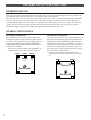
SPEAKER CONFIGURATION
Five-Speaker Configuration
This configuration is the most effective and recom-
mended one. In this configuration, the center speaker
is used for dialog when you select the digital sound
field program DOLBY PRO LOGIC, DOLBY PRO
LOGIC ENHANCED, 70mm MOVIE THEATER, TV
THEATER, or SPORTS.
• Set the center channel mode to the “NORMAL” or
“WIDE” position. (For details, refer to page 19.)
Main L Center Main R
Dialogue
Surround sound
Dialogue
Surround sound
Rear L
Rear R
Four-Speaker Configuration
The center speaker is not used in this configuration. If
the digital sound field program DOLBY PRO LOGIC,
DOLBY PRO LOGIC ENHANCED, 70mm MOVIE
THEATER, TV THEATER, or SPORTS is selected, the
center sound along with the front effects are output
from the left and the right front speakers. However,
the sound effect of other programs can be the same as
that of the other configurations.
• Be sure to set the center channel mode to the
“PHANTOM” position. (For details, refer to page
19.)
Main L Main R
DialogueDialogue
Surround soundSurround sound
Dialogue
Surround sound
Rear L Rear R

9
ENGLISH
SPEAKER PLACEMENT
The recommended speaker configuration, the five-speaker configuration, will require two speaker pairs: front
speakers and rear speakers, plus a center speaker. When you place these speakers, refer to the following:
Front: In normal position. (The position of a standard
stereo speaker setup)
Center: Precisely between the front speakers. (To avoid
interference with TV sets, use a magnetically
shielded speaker.) When two center speakers are
used, place these to the right and left of your TV
set or video monitor.
Rear: Behind your listening position, facing slightly
inward. Nearly six feet (approx. 1.8 m) up from the
floor.
Rear L
Front R
Front L
Rear R
Center

10
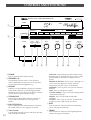
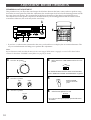
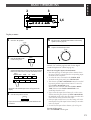
1 POWER
Press to turn the RX-V990 on and off.
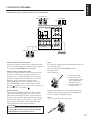
2 SPEAKERS A, B
Press button A or B to select a set of speakers.
(Press both buttons to select two sets of speakers,
or leave them off for headphone use.)
3 PHONES
Connect a set of headphones for private listening.
(Turn off the speakers 2 and the Digital Sound
Field Processor D. See page 23 for details; turn the
volume down to protect your hearing.)
4 TONE BYPASS
Press to bypass the Treble, and Bass controls (to
evaluate tone enhancements. See page 23 for
details).
5 BASS EXTENSION
Press to boost the low end frequencies to increase
the sound of the bass. See page 23 for details.
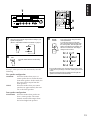
6 Tuner Section
Use the Tuner controls to store and select up to 40
AM or FM preset stations.
A/B/C/D/E - Repeatedly press this button to turn
through pages A through E to enter, edit, or select
preset stations in memory. Each page offers 8
presets.
PRESET STATIONS - Press button 1 through 8 to
access any of the 40 preset stations (used in
conjunction with the A/B/C/D/E button).
MEMORY - Press to place a new preset station in
memory.
EDIT - Press to edit preset stations.
TUNING MODE - Press to select the tuning mode
: Automatic or Manual.
FM/AM - Press to select FM or AM radio
reception.
TUNING - Press “Up” or “Down” to tune to the
frequency of the radio station you desire.
7 BASS
Turn to increase or decrease the low frequencies
(bass). See page 23 for details.
8 TREBLE
Turn to increase or decrease the high frequencies
(treble). See page 23 for details.
CONTROLS AND FUNCTIONS
DELAY TIME
CENTER REAR
CENTER
MODE
DOWN
TUNING
UP
FM/AM
TUNING
MODE
EDIT
MEMORY
POWER
A/B/C/D/E
MAN’L/AUTO FM AUTO/MAN’L MONO
I 2345678
PRESET STATIONS
CINEMA DSP
NATURAL SOUND STEREO RECEIVER
RX–V990
LEVEL
PHANTOM
SPEAKERS
CINEMA DSP
PRO LOGIC
A
SPEAKERS
B
ENHANCED
SPEAKERS
AB
PHONES
ON
OFF
TONE
BYPASS
BASS TREBLE BALANCE
55
4
3
2
l
0
l
2
3
4
55
4
3
2
l
0
l
2
3
4
55
4
3
2
l
0
l
2
3
4
L
R
ON
OFF
BASS
EXTENSION
REC OUT
LD/TV
VCR 1
TAPE 1
TUNER
CD
PHONO
VIDEO AUX
VCR 2
SOURCE
2
345 7 8960A
1

11
ENGLISH
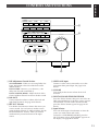
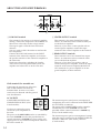
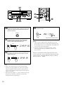
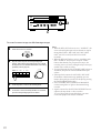
9 DSP Adjustment Control Section
CENTER MODE - When you are using Dolby Pro-
Logic, this button selects one of the three center
channel modes.
DELAY TIME - Increase (+) or decrease (–) the
delay time for each sound field D.
LEVEL
(CENTER, REAR) - Adjust the level of the
Center and Rear channels to achieve the best sound.
0 BALANCE
Turn to adjust the relative volume of the left and
right Front channels. See page 23 for details.
A REC OUT Selector
Use the Rec Out Selector to choose the source you
want to record. You can listen to another source
using the Input Selector E while recording. Set the
Rec Out Selector to “Source” when you want to
simultaneously record and listen to the input
source.
B VIDEO AUX Input
Connect a video source (camcorder, etc) to this
convenient front panel input. See page 16 for
details.
C VOLUME
Turn to adjust the master volume level of all
channels.
D DIGITAL SOUND FIELD PROCESSOR
Press the “Effect” button, then press one of the 10
DSP surround buttons to simulate various acoustic
environments. To turn off the surround sound,
press the “Effect” button again. See page 28 for
details.
E Input Selector
Press one of the input select buttons to select the
source you wish to hear and watch.
To listen to a 5CH DISCRT SOURCE, press the
LD/TV button so that “5CH DISCRT” appears on
the display. See page 30 for details.
CONTROLS AND FUNCTIONS
VOLUME
l6
l8
20
24
28
34
40
50
60
70
l4
l2
l0
8
6
4
3
2
l
0
–dB
JAZZ CLUB
ROCK
CONCERT
CONCERT
HALL
PRO LOGIC
ENHANCED
TV
THEATER
SPORTS
STADIUM
DIGITAL SOUND FIELD PROCESSOR
VIDEO AUX
VCR 2 VCR 1
LD/TV
TAPE 2
MONITOR
TUNER CD PHONO
EFFECT
MOVIE THEATER
70mm
CHURCH
TAPE 1
VIDEO AUX
8 VIDEO VIDEO L AUDIO R
2CH/5CH DISCRT
BC
E
D

12
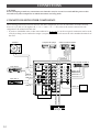
CONNECTIONS
CAUTION
Before attempting to make any connections to or from this unit, be sure to first switch OFF the power to this
unit and to any other components to which connections are being made.
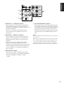
CONNECTIONS WITH OTHER COMPONENTS
When making connections between this unit and other components, be sure all connections are made correctly,
that is to say L (left) to L, R (right) to R, “+” to “+” and “–” to “–”. Also, refer to the owner’s manual for each
component to be connected to this unit.
* If you have YAMAHA audio/video unit numbered as
1
,
2
,
3
,
etc. on the rear panel, connections can be made
easily by making sure to connect the output ( or input) terminals of each unit to the same-numbered terminals of
this unit.
CD
TAPE 1
TAPE
PB
REC
OUT
TAPE 2
TAPE
PB
REC
OUT
1
3
4
4
3
10dB
0dB
-
PHONO
LD/TV
VCR 1
VCR 2
IN
OUT
IN
OUT
VIDEO SIGNAL
AUDIO SIGNAL
MONITOR
OUT
S VIDEO
AUDIO SIGNAL
LD/TV
VCR 1
VCR 2
IN
OUT
IN
OUT
VIDEO
AM
ANT
GND
FM
ANT
GND
75
Ω
UNBAL.
FRONT
IN
FRONT
LEVEL
FRONT
OUT
LD/TV
CENTER
LD/TV
SURROUND
5CH
DISCRT
INPUT
LD/TV
MAIN
Monitor TV
Tape deck 1
Turntable
Video cassette recorder 1
Video cassette recorder 2
Compact disc player
GND
VIDEO IN
Tape deck 2
LD Player
VIDEO IN
AUDIO IN
VIDEO OUT
AUDIO OUT
VIDEO OUT
AUDIO OUT
OUTPUT
AUDIO OUT
VIDEO OUT
VIDEO IN
AUDIO IN
LINE IN
LINE OUT
LINE IN
LINE OUT

13
ENGLISH
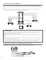
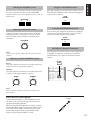
CONNECTING SPEAKERS
Connect the respective speakers to this unit as shown below:
VIDEO SIGNAL
A
B
MONITOR
OUT
S VIDEO
LD/TV
VCR 1
VCR 2
IN
OUT
IN
OUT
A OR B: 5
Ω
MIN. /SPEAKER
A
+
B: l2
Ω
MIN. /SPEAKER
OUTPUT
REAR OUT
CENTER
OUT
LOW
PASS
fo:200Hz
8
Ω
MIN. /SPEAKER
SPEAKERS
REAR
FRONT
CC
CENTER
DD
C: 8
Ω
MIN. /SPEAKER
C
+
D: 4
Ω
MIN. /SPEAKER
C
+
D
C
Right Left
Front speakers A
Rear speakers
Right Left
Right Left
Front speakers B
Center speaker(s)
Note on front speaker connection:
One or two speaker systems can be connected to this
unit. If you connect only one speaker system, connect
it to either the SPEAKERS A or B terminals.
Note on center speaker connection:
One or two center speakers can be connected to this
unit. If you cannot place the center speaker on or
under the TV, it is recommended to use two center
speakers and place them on both sides of the TV to
orient the center sound at the center position.
When connecting two center speakers, be sure to
press the CENTER speaker switch into the “C+D”
position( ). When you use a single center speaker, set
the switch to the “C” position ( ).
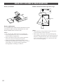
How to Connect:
Connect the SPEAKERS terminals to your speakers
with wire of the proper gauge, cut as short as pos-
sible. If the connections are faulty, no sound will be
heard from the speakers. Make sure that the polarity
of the speaker wires is correct, that is, + and – mark-
ings are observed. If these wires are reversed, the
sound will be unnatural and will lack bass.
CAUTION
Do not let the bare speaker wires touch each other and
do not let them touch the metal parts of this unit. This
could damage this unit and/or the speakers.
Note:
Use speakers with the specified impedance shown on
the rear of this unit.
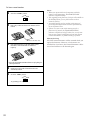
For connecting to the SPEAKER terminals
Red: positive (+)
Black: negative (–)
1 Unscrew the knob.
2 Insert the bare wire.
[Remove approx. 5mm
(1/4”) insulation from
the speaker wires.]
3 Tighten the knob and
secure the wire.
Banana Plug connections are also possible. Simply insert
the Banana Plug connector into the corresponding termi-
nal. (Not available on Singapore model.)
Note:
Use only single type banana plug cable.
1
2
3

14
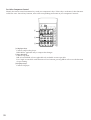
ABOUT THE ACCESSORY TERMINALS
3
2
OUTPUT
REAR OUT
CENTER
OUT
LOW
PASS
fo:200Hz
1
1 LOW PASS terminal
This terminal is for output to a monaural amplifier
driving a subwoofer. Frequencies above 200␣ Hz are
filtered out so that only the bass range remains.
The output signal is from the front and center
channels.
You may wish to add a subwoofer to reinforce the
bass frequencies.
Connect the LOW PASS terminal to the INPUT
terminal of the subwoofer amplifier, and connect
the speaker terminals of the subwoofer amplifier to
the subwoofer.
With some subwoofers, including the Yamaha
Active Servo Processing Subwoofer System, the
amplifier and subwoofer are in the same unit.
2 CENTER OUTPUT terminal
This terminal is for center channel line output.
There is no connection to this terminal when you
use the built-in amplifier.
However, if you drive a center speaker with an
external power amplifier, connect the input
terminal of the external amplifier to this terminal.
3 REAR OUTPUT terminals
These terminals are for rear channel line output.
There is no connection to these terminals when
you use the built-in amplifier.
However, if you drive rear speakers with an
external stereo power amplifier, connect the input
terminals of the external amplifier (MAIN IN or
AUX terminals of a power amplifier or an inte-
grated amplifier) to these terminals.
GND terminal (For turntable use)
Connecting the ground wire of the turn-
table to this terminal will normally
minimize hum. In some cases, better
results may be obtained with the ground
wire disconnected.
AC OUTLETS
2 SWITCHED OUTLETS and 1
UNSWITCHED OUTLET (USA,
Canada models)
Use these to connect the power
cords from your components to
this unit.
The power to the SWITCHED outlets is controlled by
this unit’s POWER switch or the provided remote
control transmitter’s POWER key. These outlets will
supply power to any connected component whenever
this unit is turned on.
SWITCHED UNSWITCHED
120V 60Hz
120W MAX. TOTAL
120V 60Hz
200W MAX.
(USA model)
GND
The maximum power (total power consumption of
components) that can be connected to the SWITCHED
AC OUTLET(S) is 120 watts.
The power to the UNSWITCHED outlets cannot be
controlled by this unit’s POWER switch or the
provided remote control transmitter’s POWER key.
(USA, Canada models only).
The maximum power (power consumption of compo-
nent) that can be connected to the UNSWITCHED AC
OUTLET is 200 watts (USA model), 180 watts
(Canada model).

15
ENGLISH
10dB
0dB
-
TAPE 2
FRONT
IN
FRONT
LEVEL
FRONT
OUT
LD/TV
CENTER
LD/TV
SURROUND
5CH
DISCRT
INPUT
LD/TV
MAIN
5
4
6
7
TAPE 2
REC
OUT
4
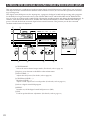
75CH DISCRT INPUT terminals
These terminals are used with a Dolby Surround
AC-3 decoder. Connect the main audio output of
the decoder to the LD/TV MAIN input terminals,
the center channel audio output to the LD/TV
CENTER input terminal, and the surround audio
output to the LD/TV SURROUND input termi-
nals.
Note:
The 5CH DISCRT INPUT terminals are for used with an
AC-3 decoder.
When you use a Dolby Surround AC-3 decoder, the LFE
(Low Frequency Effect channel) signal coming from the
AC-3 decoder to this unit must be mixed with the main
output signal. Refer to your AC-3 decoder’s operating
manual for information about mixing these signals mode.
4 FRONT CH — MAIN␣ IN terminals
These terminals are for line input to the built-in
front channel amplifier. Leave the jumper bars
connected to the PRE␣ OUT terminals when you use
the built-in amplifier.
However, if you drive front speakers with an
external stereo power amplifier, remove the
jumper bars.
5 FRONT␣ CH — PRE␣ OUT terminals
These terminals are for front main channel line
output. Leave the jumper bars connected to the
MAIN␣ IN terminals when you use the built-in
amplifier.
However, if you drive front speakers with an
external stereo power amplifier, remove the
jumper bars and connect the input terminals of the
external amplifier (MAIN IN or AUX terminals of
a power amplifier or an integrated amplifier) to
these terminals.
6 FRONT LEVEL switch
Normally set to “0␣ dB”. If desired, you can de-
crease the output level at the FRONT SPEAKERS
terminals by 10␣ dB by setting this switch to
“–10␣ dB”.

16
CONNECTING S␣ VIDEO TERMINALS
If your video cassette recorder, video disc player, monitor, etc., are equipped with “S” (high-resolution) video
terminals, connect them to this unit’s S␣ VIDEO terminals. Otherwise, use the composite video terminals of the unit.
Note:
• If video signals are sent to both the S␣ VIDEO input and composite input terminals, the input signals will be sent to the
respective S␣ VIDEO output and composite output terminals independently.
VIDEO SIGNAL
MONITOR
OUT
S VIDEO
LD/TV
VCR 1
VCR 2
IN
OUT
IN
OUT
VIDEO
Video Cassette recorder 2
Video Cassette recorder 1
LD player
VIDEO
OUT
S VIDEO
OUT
Monitor TV
VIDEO
IN
S VIDEO
IN
S VIDEO OUT
VIDEO OUT
S VIDEO IN
VIDEO IN
S-VIDEO OUT
VIDEO OUT
S-VIDEO IN
VIDEO IN
ON SCREEN DISPLAY
If you connect a video cassette recorder, video disc player, monitor, etc., to this unit, you can display DSP
program names and information about the other settings and adjustments on the video monitor screen. This
information is superimposed over the video image.
If there is no program material on the monitor, the information will be displayed over a monochromatic back-
ground.
Notes:
• If you use a video monitor that is connected to both the S␣ VIDEO and composite terminals, the screen display informa-
tion is only output from the S␣ VIDEO terminals.
• When no video signal is input to any of the S␣ VIDEO or composite video input terminals, the screen display information
is output from the S␣ VIDEO and composite MONITOR OUT terminals with a monochromatic background.
CONNECTING TO VIDEO AUX TERMINALS (FRONT PANEL)
These terminals are used to connect any video input source such as a camcorder to this unit.
AUDIO OUT
AUDIO OUT
VIDEO OUT
L
R
VIDEO
Camcorder
S-VIDEO
S VIDEO OUT
8 VIDEO
VIDEO AUX
8 VIDEO VIDEO L AUDIO R

17
ENGLISH
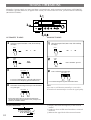
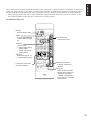
ANTENNA CONNECTIONS
• Each antenna should be connected to the designated terminals correctly, referring to the following diagram.
• Both AM and FM indoor antennas are included with this unit. In general, these antennas will probably provide
sufficient signal strength. Nevertheless, a properly installed outdoor antenna will give clearer reception than an
indoor one. If you experience poor reception quality, an outdoor antenna may result in improvement.
CD
TAPE 1
TAPE
PB
REC
OUT
TAPE 2
TAPE
PB
REC
OUT
1
3
4
4
3
10dB
0dB
-
PHONO
AUDIO SIGNAL
AM
ANT
GND
FM
ANT
GND
75
Ω
UNBAL.
FRONT
IN
FRONT
LEVEL
FRONT
OUT
AM loop
antenna
(included)
Indoor FM
antenna
(included)
Ground
Outdoor AM antenna
Outdoor FM antenna
75-ohm/300-ohm
antenna adapter
75-ohm
coaxial cable
300-ohm
feeder
Connecting the AM loop antenna
123
• The AM loop antenna should be placed apart from the main unit. The antenna may be hung on a wall.
• The AM loop antenna should be kept connected, even if an outdoor AM antenna is connected to this unit.
➀
➁
➂
GND terminal
For maximum safety and minimum interference,
connect the GND terminal to a good earth ground.
A good earth ground is a metal stake driven into
moist earth.
Notes:
• When connecting the indoor FM
antenna, insert its connector into the
FM ANT terminal firmly.
• If you need an outdoor FM antenna to
improve FM reception quality, either
300-ohm feeder or coaxial cable may be
used. In locations troubled by electrical
interference, coaxial cable is preferable.
Orient so that the best
reception is obtained.

18
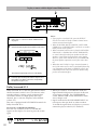
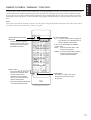
ADJUSTMENT BEFORE OPERATION
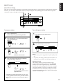
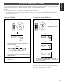
SPEAKER BALANCE ADJUSTMENT
This procedure lets you adjust the sound output level balance between the front, center, and rear speakers using
the built-in test tone generator. With this adjustment, the sound output level heard at the listening position will be
the same from each speaker. This is important for the best performance of the digital sound field processor.
The adjustment of each speaker output level should be done at your listening position with the remote control
transmitter. Otherwise, the result may not be satisfactory.
1
234
POWER
PLAY
TAPE 1
DIR A DIR B
SKIP
PHONO
CD
TUNER
STOP PLAY
SLEEP TV VCR AUX
DISC
SKIP
SEARCH
SEARCH
SEARCH
PAUSE/STOP
PAUSE/STOP
DECK
A/B
PRESET
A B C D E
REC/PAUSEREC MUTE TAPE 2 MON
PLAY LD/TV
TRANSMIT
/LEARN
YPC LEARN
USER
+
—
6
5
* If you have a video monitor connected to this unit, you should use it to display the on screen information. The
easy-to-read information will help you to perform this adjustment.
Note:
Before adjustment, make sure that the mute circuit is not engaged. While mute is engaged, no sound will be heard and an
indicator on the master VOLUME control flashes. See page 23 for details.
1
Set to the “
∞
” position.
Set the remote YPC-USER-LEARN switch to the “YPC”
position.
4
For detailed information about the remote control transmitter,
refer to “REMOTE CONTROL TRANSMITTER” on page 34.
2
Set to the “0” position.
BASS TREBLE
55
4
3
2
l
0
l
2
3
4
55
4
3
2
l
0
l
2
3
4
YPC LEARN
USER
VOLUME
l6
l8
20
24
28
34
40
50
60
70
l4
l2
l0
8
6
4
3
2
l
0
–dB
5
POWER
Press the POWER
switch to turn on the
power.
6
Select the main speakers to be used.
• If you use two main speaker systems, press both the A and
B switches.
SPEAKERS
AB
3
BALANCE
55
4
3
2
l
0
l
2
3
4
LR
Set to the “0” position.

19
ENGLISH
7
STOP
VCR 1
VCR 2
V–AUX
CHAPTER/CH
—
+
DISPLAY
MASTER
VOLUME
—
+
TEST
MUTING
+
+
+
—
—
—
DSP
HALL
EFFECT
CHURCH
CENTER LEVEL
REAR LEVEL
DELAY
TIME
MOVIE THEATER
JAZZ CLUB
STADIUM
PRO LOGIC
SURROUND
SPORTS
ENHANCED
ROCK
THEATER
70mm TV
1234
5678
910
ON/OFF
RESET CLEAR
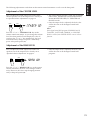
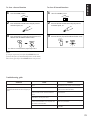
8
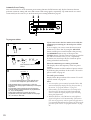
9
In step 7, when you select the center mode, note the
following.
Five speaker configuration
NORMAL: Select this mode when you use a
center speaker that is smaller than the
front main speakers. In this mode, the
bass tone will be output from the
front speakers.
WIDE: Select this mode when your center
speakers are approximately the same
size as the front speakers.
Four speaker configuration
PHANTOM: Select this mode when you do not
have a center speaker. The center
channel sound will be output from
the left and right font speakers.
—
+
7
8
Select the center channel output mode according to your
speaker configuration.
(Refer to “SPEAKER CONFIGURATION” on page 8.)
CENTER
MODE
NORMAL
WIDE
PHANTOM
• If your video monitor is on, the state of the test tone output
is also shown by an image of an audio listening room on the
screen.
• The test tone from the left rear speaker and the right rear
speaker will be heard at the same time.
9
Turn up the volume using the remote
control transmitter.
You will hear a test tone (like pink
noise) from the left front speaker, then
the center speaker, then the right front
speaker, and then the rear speakers, for
about two seconds each. The display
changes as shown below.
TEST
MASTER
VOLUME
Press the TEST button to run the Dolby
test.

20
10
12
11
STOP
VCR 1
VCR 2
V–AUX
CHAPTER/CH
—
+
DISPLAY
MASTER
VOLUME
—
+
TEST
MUTING
+
+
+
—
—
—
DSP
HALL
EFFECT
CHURCH
CENTER LEVEL
REAR LEVEL
DELAY
TIME
MOVIE THEATER
JAZZ CLUB
STADIUM
PRO LOGIC
SURROUND
SPORTS
ENHANCED
ROCK
THEATER
70mm TV
1234
5678
910
ON/OFF
RESET CLEAR
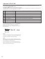
13
12
11
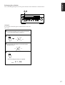
Notes:
• Once you have completed these adjustments, you can
adjust whole sound level on your audio system by using
the VOLUME control (or the MASTER VOLUME keys
on the remote control transmitter).
• If you use external power amplifiers, their volume
controls may also need to be adjusted to achieve the
proper balance.
If there is insufficient sound output from the center
and rear speakers, you may decrease the front speaker
output level by setting the FRONT LEVEL switch on
the rear panel to “–10 dB”.
Note:
• If the center channel mode is in the “PHANTOM”
position, the sound output level of the center speaker
cannot be adjusted. This is because in this mode, the
center sound is automatically output from the left and
right front speakers.
• If you press the LEVEL +/– switch without previously
pressing the CENTER, or REAR switch, the last
channel selected will be changed.
10
11
12
13
Adjust the BALANCE control so that the test tone sound
output level of the left front speaker and the right front
speaker are the same.
Adjust the sound output level of the rear speakers to be
at the same level as that of the front speakers with the
REAR LEVEL keys.
Adjust the test tone sound output level of the center
speaker to be at the same level as that of the front
speakers with the CENTER LEVEL keys.
Cancel the test tone.
BALANCE
55
4
3
2
l
0
l
2
3
4
LR
TEST
CENTER
LEVEL
REAR
LEVEL
PRO LOGIC
The previous mode is selected.
La pagina sta caricando ...
La pagina sta caricando ...
La pagina sta caricando ...
La pagina sta caricando ...
La pagina sta caricando ...
La pagina sta caricando ...
La pagina sta caricando ...
La pagina sta caricando ...
La pagina sta caricando ...
La pagina sta caricando ...
La pagina sta caricando ...
La pagina sta caricando ...
La pagina sta caricando ...
La pagina sta caricando ...
La pagina sta caricando ...
La pagina sta caricando ...
La pagina sta caricando ...
La pagina sta caricando ...
La pagina sta caricando ...
La pagina sta caricando ...
La pagina sta caricando ...
La pagina sta caricando ...
-
 1
1
-
 2
2
-
 3
3
-
 4
4
-
 5
5
-
 6
6
-
 7
7
-
 8
8
-
 9
9
-
 10
10
-
 11
11
-
 12
12
-
 13
13
-
 14
14
-
 15
15
-
 16
16
-
 17
17
-
 18
18
-
 19
19
-
 20
20
-
 21
21
-
 22
22
-
 23
23
-
 24
24
-
 25
25
-
 26
26
-
 27
27
-
 28
28
-
 29
29
-
 30
30
-
 31
31
-
 32
32
-
 33
33
-
 34
34
-
 35
35
-
 36
36
-
 37
37
-
 38
38
-
 39
39
-
 40
40
-
 41
41
-
 42
42


Yamaha RX-V990 Manuale utente
- Categoria
- Lettori di cassette
- Tipo
- Manuale utente
in altre lingue
- English: Yamaha RX-V990 User manual
- français: Yamaha RX-V990 Manuel utilisateur
- español: Yamaha RX-V990 Manual de usuario
- Deutsch: Yamaha RX-V990 Benutzerhandbuch
- русский: Yamaha RX-V990 Руководство пользователя
- Nederlands: Yamaha RX-V990 Handleiding
- português: Yamaha RX-V990 Manual do usuário
- dansk: Yamaha RX-V990 Brugermanual
- čeština: Yamaha RX-V990 Uživatelský manuál
- polski: Yamaha RX-V990 Instrukcja obsługi
- svenska: Yamaha RX-V990 Användarmanual
- Türkçe: Yamaha RX-V990 Kullanım kılavuzu
- suomi: Yamaha RX-V990 Ohjekirja
- română: Yamaha RX-V990 Manual de utilizare
Documenti correlati
-
Yamaha RX-V660 Manuale del proprietario
-
-
-
-
-
-
-
-
-