
CAME S.p.A.
Via Martiri Della Libertà, 15
31030 - Dosson di Casier
Treviso - Italy
001DC02LUXO
L1 L2
Lb
Lb
Lb
Ld
Ld
Ld
La
L3
001DC006AC
Lc
001DC012AC 001DC012AC
001DC008AC
001DC010AC
001CS2PLCO
001DC01ENIGMA
001DC02ENIGMA
001DC01ENIGMA
001DC02ENIGMA
001DC01ENIGMA
001DC02ENIGMA
001DC01ENIGMA
001DC02ENIGMA
Lb
La
MAX 8
L1 L2
Lb
Lb
L3
Lc
001DC012AC
001DC008AC
001CS2PLCO
001DC012AC001DC012AC001DC012AC
001DC012AC
001DC012AC 001DC012AC
001DC006AC
001DC010AC
001DC01ENIGMA
001DC02ENIGMA
001DC01ENIGMA
001DC02ENIGMA
001DC01ENIGMA
001DC02ENIGMA
A
F
KL
GHI
J
B C D
1
212
161
29
60
83,5
83,5
CL.RES
SW4
ENTRY P. PRES.
SW5
M1
A V
CL.RES CL.RES CL.RES
001DC006AC
1 2 3
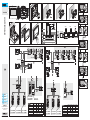
VCM/1D VCM/2D UTP/CAT 5 2x1,5mm2
La+Lb ≤100 m – ≤100 m –
Lc ≤75 m – – ≤100 m
L1, L2, L3 – ≤100 m – –
L1 + L2 + L3 – ≤300 m – –
La + Lb + L1 (L2, L3) ≤150 m
La + Lb + L1+ L2 + L3 ≤600 m
Ld ≤100 m ≤75 m
VCM/1D VCM/2D UTP/CAT 5 2x1,5mm2
La+Lb ≤100 m – ≤100 m –
Lc ≤75 m – – ≤100 m
L1, L2, L3 – ≤100 m – –
L1 + L2 + L3 – ≤300 m – –
La + Lb + L1 (L2, L3) ≤150 m
La + Lb + L1+ L2 + L3 ≤600 m
B
C
F
4
G
E
H
I
212
161
29
60
83,5
83,5
2
1
A
2
E
A
x5
FA00941M4A - ver. 1 - 09/2017
FA00941M4A
IT
Italiano
EN
English
FR
Français
RU
Pусский

FA00941M4A - ver. 1 - 09/2017
ITALIANO
Avvertenze generali
• Leggere attentamente le istruzioni, prima di
iniziare l’installazione ed eseguire gli interventi
come specificato dal costruttore.
• L’installazione, la programmazione, la mes-
sa in servizio e la manutenzione del prodotto
deve essere eettuata solo da personale tec-
nico qualificato ed opportunamente adde-
strato nel rispetto delle normative vigenti ivi
comprese le osservanze sulla prevenzione
infortuni.
• Prima di eettuare ogni operazione di pulizia
o di manutenzione, togliere l’alimentazione.
• L’apparecchio dovrà essere destinato solo
all’uso per il quale è stato studiato.
• Il costruttore non può comunque essere
considerato responsabile per eventuali danni
derivanti da usi impropri, erronei ed irragio-
nevoli.
Descrizione
Videocitofonico vivavoce con display LCD da 7''
con alimentazione locale.
Morsettiera H
+ – Alimentazione locale
B Ingresso linea BUS
–+ Chiamata da pianerottolo
AL Ingresso allarme
Resistenza di fine linea (CL.RES) I
Il ponticello deve essere inserito solo nell'ultimo
dispositivo della linea.
Dati tecnici
Tipo
001DC02LUXO
Alimentazione locale
(VDC)
16÷18
Assorbimento (mA max)
300
Assorbimento in stand
by (mA)
<10
Assorbimento singolo LED
(mA) (panico, esclusione
suoneria)
1
Temperatura di stoccaggio
(°C)
-25 ÷ +70
Temperatura di
funzionamento (°C)
0 ÷ +35
Grado IP
20
Standard video
PAL/NTSC
Display LCD TFT a colori
(pollici)
7
Installazione
Installare il dispositivo ad un’altezza adeguata
all’utente.
• A Premere il pulsante 1; sganciare il sup-
porto dal dispositivo facendolo scorrere 2.
• Fissare il supporto alla scatola da incasso:
tonda Ø 60mm B oppure rettangolare 503
CD. Utilizzare le viti in dotazione, rispettare
l’indicazione TOP ed evitare il serraggio ecces-
sivo delle viti.
• Eseguire i collegamenti e agganciare il dispo-
sitivo al supporto EF.
• Per sganciare l’apparecchio dal supporto pre-
mere il pulsante e sollevare il dispositivo G.
Per l’installazione da incasso fare riferimento al
manuale del kit da incasso.
Configurazione melodie J
☞ Bisogna eseguire, in successione, tutte
le fasi di programmazione descritte di se-
guito:
1- Ingresso in Programmazione.
Premere per 5 volte il pulsante entro 5 s 1.
Un breve segnale acustico conferma l’ingresso in
programmazione.
2- Programmazione della melodia associata
alla chiamata dal posto esterno.
Per ascoltare in sequenza le melodie premere il
tasto 2.
Per selezionare la melodia ed uscire dalla pro-
grammazione premere il tasto 3.
Per selezionare la melodia e proseguire con la
programmazione premere il tasto 4.
3- Programmazione della melodia associata
alla chiamata dal pianerottolo.
Per ascoltare in sequenza le melodie premere il
tasto 5.
Per selezionare la melodia ed uscire dalla pro-
grammazione premere il tasto 6.
Per selezionare la melodia e proseguire con la
programmazione premere il tasto G.
4- Programmazione del numero di squilli di
chiamata.
Premere il tasto 8 tante volte quanti sono
gli squilli desiderati (da 1 a 6 squilli). Dopo 3
secondi dall’ultima pressione del tasto verrà ri-
prodotta la chiamata selezionata per il numero
di squilli prescelto.
Per uscire dalla programmazione premere il ta-
sto I.
☞ Per la programmazione della chiamata,
vedere la documentazione dei posti esterni.
Schemi di installazione K L
L Nel caso si utilizzi un cavo UTP/CAT 5
ogni coppia di cavi deve alimentare un solo
derivato.
Il prodotto è conforme alle direttive di riferi-
mento vigenti.
Dismissione e smaltimento. Non disperdere
nell’ambiente l’imballaggio e il dispositivo alla
fine del ciclo di vita, ma smaltirli seguendo le
norme vigenti nel paese di utilizzo del prodot-
to. I componenti riciclabili riportano simbolo e
sigla del materiale.
I DATI E LE INFORMAZIONI INDICATE IN QUE-
STO MANUALE SONO DA RITENERSI SUSCET-
TIBILI DI MODIFICA IN QUALSIASI MOMENTO
E SENZA OBBLIGO DI PREAVVISO. LE MISU-
RE, SE NON DIVERSAMENTE INDICATO, SONO
IN MILLIMETRI.
ENGLISH
General precautions
• Read the instructions carefully before begin-
ning the installation and carry out the actions
as specified by the manufacturer.
• The installation, programming, commission-
ing and maintenance of the product must be
carried out only by qualified technical person-
nel, correctly trained with regard to respecting
the regulations in force, including the imple-
mentation of accident prevention measures.
• Before carrying out any cleaning or mainte-
nance, disconnect the power supply.
• The equipment must only be used for the
purpose for which it was designed.
• The manufacturer declines all liability for
any damage as a result of improper, incorrect
or unreasonable use.
Description
Hands-free video receiver with 7" LCD display
and local power supply.
Terminal board H
+ – Local power supply
B BUS line input
–+ Doorbell
AL Alarm input
Closing resistance (CL.RES) I
The jumper should be inserted in the last device
in the line only.
Technical data
Type
001DC02LUXO
Local power supply (VDC)
16-18
Consumption (mA max)
300
Consumption in stand-by
mode (mA)
<10
Consumption of single
LED (mA) (panic alarm,
disabling ringtone)
1
Storage temperature (°C)
-25 to +70
Operating temperature
(°C)
0 to +35
IP Rating
20
Video standard
PAL/NTSC
LCD TFT colour display
(inches)
7
Installation
Install the device at a suitable height for the
user.
• A Press button 1; unhook the device from
the bracket by sliding it o 2.
• Fasten the bracket to the recessed box:
round Ø 60mm B or rectangular 503 CD.
Use the screws provided, follow the direction
marked “TOP” and avoid overtightening the
screws.
• Make the connections and fit the device onto
the bracket EF.
• To unhook the unit from the bracket, press the
button and lift the device G.
For recessed installation refer to the recessing
kit manual.
Ringtone configuration J
☞ All the programming stages described
below must be carried out in sequence:
1- Accessing programming mode
Press button 5 times in 5 secs 1.
A short beep confirms that you have entered
programming mode.
2- Programming the melody associated with
a call from the entry panel
To listen to the melodies in sequence, press
button 2.
To select the melody and exit programming,
press button 3.
To select the melody and continue with pro-
gramming, press button 4.
3- Programming the melody associated with
a call from the floor
To listen to the melodies in sequence, press
button 5.
To select the melody and exit programming,
press button 6.
To select the melody and continue with pro-
gramming, press button G.
4- Programming the number of rings
Press button 8 as many times as you want
the call to ring (from 1 to 6 rings). Three sec-
onds after the button is last pressed, the select-
ed call is played back with the chosen number
of rings.
To exit programming, press button I.
☞ See the entry panel documentation for
call programming.
Installation diagrams K L
L If using a UTP/CAT 5 cable, each pair of
cables must power only one receiver.
This product complies with the relevant direc-
tives in force.
Decommissioning and disposal. Dispose of
the packaging and the device at the end of its
life cycle responsibly, in compliance with the
laws in force in the country where the prod-
uct is used. The recyclable components are
marked with a symbol and the material's ID
marker.
THE DATA AND INFORMATION SHOWN IN THIS
MANUAL ARE TO BE CONSIDERED AS SUB-
JECT TO CHANGE AT ANY TIME AND WITH-
OUT THE NEED FOR ANY ADVANCE WARN-
ING. MEASUREMENTS, UNLESS OTHERWISE
INDICATED, ARE IN MILLIMETRES.
РУССКИЙ
Общие правила безопасности
• Внимательно прочитайте инструкции,
прежде чем приступить к установке и вы-
полнению работ, согласно указаниям фир-
мы-изготовителя.
• Монтаж, программирование, включе-
ние и техобслуживание изделия должны
выполняться только квалифицированным
и обученным персоналом в полном соот-
ветствии с действующими нормативами,
включая соблюдение правил техники без-
опасности
• Обесточьте все устройства перед выпол-
нением работ по чистке и техобслужива-
нию.
• Это изделие должно использоваться ис-
ключительно по назначению.
• Фирма-изготовитель снимает с себя
всякую ответственность за ущерб, нане-
сенный неправильным, ошибочным или
небрежным использованием изделия.
Описание
Абонентское видеоустройство с громкой
связью, ЖК-дисплеем 7'' и локальным элек-
тропитанием.
Клеммная колодка H
+ – Локальное электропитание
B Вход линии шины
–+ Дверной звонок
AL Вход тревожной сигнализации
Концевой резистор (CL.RES) I
Перемычка должна быть установлена только
на последнем устройстве линии.
Технические характеристики
Модель
001DC02LUXO
Локальное электропитание
(=В)
16-18
Макс. потребляемый
ток (мА)
300
Потребление в режиме
ожидания (мА)
<10
Потребление тока одним
светодиодом (мA) (паника,
беззвучный режим)
1
Диапазон температур
хранения (°C)
-25 — +70
Диапазон рабочих
температур (°C)
0 — +35
Класс защиты (IP)
20
Видеостандарт
PAL/NTSC
Цветной ЖК-дисплей TFT
(в дюймах)
7
Монтаж
Установите устройство на удобной для
пользователя высоте.
• A Нажмите кнопку 1; вытащите суппорт
из устройства 2.
• Прикрепите суппорт к монтажной коробке:
круглой Ø 60 мм B или прямоугольной 503
CD. Используйте прилагаемые винты, со-
блюдая указание «TOP» («ВВЕРХ») и избегая
чрезмерного затягивания винтов.
• Выполните электрические подключения и
прикрепите устройство к суппорту EF.
• Чтобы отсоединить устройство от суппорта,
нажмите кнопку и поднимите устройство G.
Для встроенного монтажа руководствуйтесь
инструкцией, прилагаемой к комплекту для
встроенного монтажа.
Настройка мелодий J
☞ Необходимо последовательно выпол-
нить все этапы программирования, опи-
санные ниже:
1. Вход в режим программирования.
Нажмите 5 раз кнопку в течение 5 секунд
1.
Короткий звуковой сигнал подтвердит вход в
режим программирования.
2. Программирование мелодии вызова с
вызывной панели.
Для последовательного прослушивания ме-
лодий нажмите кнопку 2.
Для выбора мелодии и выхода из режима
программирования нажмите кнопку 3.
Для выбора мелодии и продолжения про-
граммирования нажмите кнопку 4.
3. Программирование мелодии дверного
звонка.
Для последовательного прослушивания ме-
лодий нажмите кнопку 5.
Для выбора мелодии и выхода из режима
программирования нажмите кнопку 6.
Для выбора мелодии и продолжения про-
граммирования нажмите кнопку G.
4. Программирование количества звон-
ков во время вызова.
Нажмите клавишу 8 столько раз, сколь-
ко звонков требуется для вызова (от 1 до 6).
Спустя 3 секунды после последнего нажатия
клавиши мелодия вызова будет воспроизве-
дена заданное количество раз.
Для выхода из режима программирования
нажмите кнопку I.
☞ Информация о программировании
вызовов приведена в документации к вы-
зывной панели.
Схемы установки K L
L В случае использования кабеля UTP/
CAT 5 каждая пара проводов должна пи-
тать только одно абонентское устройство.
Изделие соответствует требованиям дей-
ствующих нормативов.
Утилизация. Не выбрасывайте упаковку
и устройство в окружающую среду. Ути-
лизируйте их в соответствии с требова-
ниями законодательства, действующего в
стране установки. Компоненты, пригодные
для повторного использования, отмечены
специальным символом с обозначением
материала.
КОМПАНИЯ CAME S.P.A. СОХРАНЯЕТ ЗА
СОБОЙ ПРАВО НА ИЗМЕНЕНИЕ СОДЕРЖА-
ЩЕЙСЯ В ЭТОЙ ИНСТРУКЦИИ ИНФОРМА-
ЦИИ В ЛЮБОЕ ВРЕМЯ И БЕЗ ПРЕДВАРИ-
ТЕЛЬНОГО УВЕДОМЛЕНИЯ. ВСЕ РАЗМЕРЫ
ПРИВЕДЕНЫ В ММ, ЕСЛИ НЕ УКАЗАНО
ИНОЕ.
FRANÇAIS
Instructions générales
• Lire attentivement les instructions avant
toute opération d'installation et eectuer les
interventions comme indiqué par le fabricant.
• L’installation, la programmation, la mise en
service et l'entretien du produit ne doivent être
eectués que par des techniciens qualifiés et
dans le strict respect des normes en vigueur,
y compris des règles sur la prévention des
accidents.
• Avant toute opération de nettoyage ou d'en-
tretien, mettre hors tension.
• L'appareil ne devra être destiné qu'à l'utili-
sation pour laquelle il a été conçu.
• Le fabricant décline toute responsabilité en
cas d'éventuels dommages provoqués par
des utilisations impropres, incorrectes et dé-
raisonnables.
Description
Portier vidéo mains libres avec écran LCD 7'' à
alimentation locale.
Bornier H
+ – Alimentation locale
B Entrée ligne BUS
–+ Appel depuis palier
AL Entrée alarme
Résistance de terminaison de ligne (CL.RES)
I
Le shunt ne doit être activé que dans le dernier
dispositif de la ligne.
Données techniques
Type
001DC02LUXO
Alimentation locale (VDC)
16 - 18
Absorption (mA max.)
300
Absorption en mode veille
(mA)
<10
Absorption LED simple (mA)
(panique, désactivation
sonnerie)
1
Température de stockage
(°C)
-25 à +70
Température de
fonctionnement (°C)
0 à +35
Degré IP
20
Standard vidéo
PAL/NTSC
Écran LCD TFT couleur
(pouces)
7
Installation
Installer le dispositif à la hauteur convenant
à l’utilisateur.
• A Appuyer sur le bouton 1 ; décrocher le
support du dispositif en le faisant glisser 2.
• Fixer le support au boîtier à encastrer :
rond Ø 60mm B ou rectangulaire 503 CD.
Utiliser les vis fournies sans trop les serrer et
respecter l’indication TOP.
• Eectuer les branchements et fixer le disposi-
tif au support EF.
• Pour décrocher l’appareil du support, appuyer
sur le bouton et soulever le dispositif G.
Pour la version à encastrer, se référer au manuel
du kit à encastrer.
Configuration des mélodies J
☞ Eectuer, l’une après l’autre, toutes les
phases de programmation décrites ci-après :
1- Entrée en mode programmation.
Appuyer 5 fois sur le bouton en 5 s 1.
Un signal sonore bref confirme l’entrée en mode
programmation.
2- Programmation de la mélodie associée à
l’appel provenant du poste externe.
Pour écouter les mélodies l’une après l’autre,
appuyer sur la touche 2.
Pour sélectionner la mélodie et sortir de la pro-
grammation, appuyer sur la touche 3.
Pour sélectionner la mélodie et poursuivre la
programmation, appuyer sur la touche 4.
3- Programmation de la mélodie associée à
l’appel provenant du palier.
Pour écouter les mélodies l’une après l’autre,
appuyer sur la touche 5.
Pour sélectionner la mélodie et sortir de la pro-
grammation, appuyer sur la touche 6.
Pour sélectionner la mélodie et poursuivre la
programmation, appuyer sur la touche G.
4- Programmation du nombre de sonneries
de l’appel.
Appuyer sur la touche 8 autant de fois que
le nombre de sonneries souhaité (de 1 à 6
sonneries). Au bout de 3 secondes à compter
du dernier enfoncement de la touche, l’appel
sélectionné sera reproduit selon le nombre de
sonneries choisi.
Pour sortir du menu de programmation, appuyer
sur la touche I.
☞ Pour la programmation de l’appel, voir la
documentation des postes externes.
Schémas d'installation K L
L En cas d’utilisation d’un câble UTP/CAT
5, chaque paire de câbles ne doit alimenter
qu’un seul poste.
Ce produit est conforme aux directives de ré-
férence en vigueur.
Mise au rebut et élimination. Ne pas jeter
l'emballage et le dispositif dans la nature au
terme du cycle de vie de ce dernier, mais les
éliminer selon les normes en vigueur dans le
pays où le produit est utilisé. Le symbole et le
sigle du matériau figurent sur les composants
recyclables.
LES DONNÉES ET LES INFORMATIONS
CONTENUES DANS CE MANUEL SONT SUS-
CEPTIBLES DE SUBIR DES MODIFICATIONS
À TOUT MOMENT ET SANS AUCUN PRÉAVIS.
LES DIMENSIONS SONT EXPRIMÉES EN MIL-
LIMÈTRES, SAUF INDICATION CONTRAIRE.
-
 1
1
-
 2
2


in altre lingue
- français: CAME LUXO Guide d'installation
Documenti correlati
-
CAME AGATA Guida d'installazione
-
-
-
-
-
-
-
-
-