
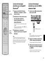
Safety Instructions ................................................ 2
Connections .......................................................... 7
Basic operations ................................................. 18
English
Consignes de sécurité......................................... 22
Raccordements................................................... 27
Fonctionnement de base .................................... 38
Français
Instrucciones de segurida................................... 42
Conexiones ......................................................... 45
Operaciones básicas .......................................... 56
Español
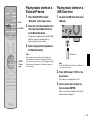
Правила техники безопасности ...................... 60
Подключения .................................................... 63
Основные операции.......................................... 74
Русский
AV Receiver
Ampli-tuner audio-vidéo
Quick Start Guide
Guide de démarrage rapide
Guía de inicio rápida
Краткое руководство по началу работы
EN
FE
ES
RU
UCABGF

2 En
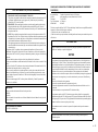
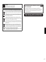
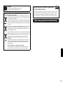
• Explanation of Graphical Symbols
The lightning flash with arrowhead symbol, within an equilateral triangle, is
intended to alert you to the presence of uninsulated “dangerous voltage” within the
product’s enclosure that may be of sufficient magnitude to constitute a risk of
electric shock to persons.
The exclamation point within an equilateral triangle is intended to alert you to the
presence of important operating and maintenance (servicing) instructions in the
literature accompanying the appliance.
1 Read these instructions.
2 Keep these instructions.
3 Heed all warnings.
4 Follow all instructions.
5 Do not use this apparatus near water.
6 Clean only with dry cloth.
7 Do not block any ventilation openings. Install in accordance with the manufacturer’s instructions.
8 Do not install near any heat sources such as radiators, heat registers, stoves, or other apparatus
(including amplifiers) that produce heat.
9 Do not defeat the safety purpose of the polarized or grounding-type plug. A polarized plug has two
blades with one wider than the other. A grounding type plug has two blades and a third grounding
prong. The wide blade or the third prong are provided for your safety. If the provided plug does not
fit into your outlet, consult an electrician for replacement of the obsolete outlet.
10 Protect the power cord from being walked on or pinched particularly at plugs, convenience
receptacles, and the point where they exit from the apparatus.
11 Only use attachments/accessories specified by the manufacturer.
12 Use only with the cart, stand, tripod, bracket, or table specified by the
manufacturer, or sold with the apparatus. When a cart is used, use caution when
moving the cart/apparatus combination to avoid injury from tip-over.
13 Unplug this apparatus during lightning storms or when unused for long periods of
time.
14 Refer all servicing to qualified service personnel. Servicing is required when the
apparatus has been damaged in any way, such as power-supply cord or plug is damaged, liquid has
been spilled or objects have fallen into the apparatus, the apparatus has been exposed to rain or
moisture, does not operate normally, or has been dropped.
English
A (power) key
Turns on the power of this unit or sets it to the standby mode.
This product is for ordinary homes. Do not use for applications requiring high reliability, such as
managing lives, health care or high-value assets.
For more detailed information, refer to the Owner’s Manual on the CD-ROM. To view the Owner’s
Manual, click on “English” in the screen displayed automatically when you insert the CD-ROM
into your PC, or click on the model name if the screen to select models is displayed, and then click
on “English” in the next screen. Then, follow the onscreen instructions.
If the screen is not displayed automatically, open the “index.html” in the CD-ROM.
Caution: Do not attempt to play this CD-ROM in an audio player.
The Owner’s Manual contained in the CD-ROM can be downloaded from the following website.
http://download.yamaha.com/
IMPORTANT SAFETY INSTRUCTIONS
CAUTION
CAUTION: TO REDUCE THE RISK OF
ELECTRIC SHOCK, DO NOT REMOVE
COVER (OR BACK). NO USER-SERVICEABLE
PARTS INSIDE. REFER SERVICING TO
QUALIFIED SERVICE PERSONNEL.
RISK OF ELECTRIC
SHOCK DO NOT OPEN

En 3
COMPLIANCE INFORMATION STATEMENT (DECLARATION OF CONFORMITY
PROCEDURE)
Responsible Party: Yamaha Corporation of America A/V Division
Address: 6600 Orangethorpe Avenue, Buena Park, CA 90620
Telephone: 714-522-9011
Type of Equipment: AV Receiver
Model Name: RX-A670
This device complies with Part 15 of FCC Rules and Industry Canada licence-exempt RSS standard(s).
Operation is subject to the following two conditions:
(1) this device may not cause interference, and
(2) this device must accept any interference, including interference that may cause undesired operation
of this device.
FCC INFORMATION (for US customers)
1 IMPORTANT NOTICE: DO NOT MODIFY THIS UNIT!
This product, when installed as indicated in the instructions contained in this manual, meets FCC
requirements. Modifications not expressly approved by Yamaha may void your authority,
granted by the FCC, to use the product.
2 IMPORTANT: When connecting this product to accessories and/or another product use only
high quality shielded cables. Cable/s supplied with this product MUST be used. Follow all
installation instructions. Failure to follow instructions could void your FCC authorization to use
this product in the USA.
3 NOTE: This product has been tested and found to comply with the requirements listed in FCC
Regulations, Part 15 for Class “B” digital devices. Compliance with these requirements provides
a reasonable level of assurance that your use of this product in a residential environment will not
result in harmful interference with other electronic devices.
This equipment generates/uses radio frequencies and, if not installed and used according to the
instructions found in the users manual, may cause interference harmful to the operation of other
electronic devices.
Compliance with FCC regulations does not guarantee that interference will not occur in all
installations. If this product is found to be the source of interference, which can be determined by
turning the unit “OFF” and “ON”, please try to eliminate the problem by using one of the following
measures:
Relocate either this product or the device that is being affected by the interference.
Utilize power outlets that are on different branch (circuit breaker or fuse) circuits or install AC line
filter/s.
In the case of radio or TV interference, relocate/reorient the antenna. If the antenna lead-in is 300
ohm ribbon lead, change the lead-in to coaxial type cable.
If these corrective measures do not produce satisfactory results, please contact the local retailer
authorized to distribute this type of product. If you can not locate the appropriate retailer, please
contact Yamaha Corporation of America A/V Division, 6600 Orangethorpe Avenue, Buena Park,
CA 90620, USA.
The above statements apply ONLY to those products distributed by Yamaha Corporation of
America or its subsidiaries.
IMPORTANT
Please record the serial number of this unit in the space below.
MODEL:
Serial No.:
The serial number is located on the rear of the unit. Retain this Owner's Manual in a safe place for
future reference.
FOR CANADIAN CUSTOMERS
CAN ICES-3(B)/NMB-3(B).
FCC CAUTION
Changes or modifications not expressly approved by the party responsible for compliance could
void the user’s authority to operate the equipment.
NOTICE
This equipment has been tested and found to comply with the limits for a Class B digital device,
pursuant to part 15 of the FCC Rules. These limits are designed to provide reasonable protection
against harmful interference in a residential installation. This equipment generates, uses and can
radiate radio frequency energy and, if not installed and used in accordance with the instructions,
may cause harmful interference to radio communications. However, there is no guarantee that
interference will not occur in a particular installation. If this equipment does cause harmful
interference to radio or television reception, which can be determined by turning the equipment off
and on, the user is encouraged to try to correct the interference by one or more of the following
measures:
– Reorient or relocate the receiving antenna.
– Increase the separation between the equipment and receiver.
– Connect the equipment into an outlet on a circuit different from that to which the receiver is
connected.
– Consult the dealer or an experienced radio/TV technician for help.
This equipment complies with FCC/IC radiation exposure limits set forth for an uncontrolled
environment and meets the FCC radio frequency (RF) Exposure Guidelines and RSS-102 of the IC
radio frequency (RF) Exposure rules. This equipment should be installed and operated keeping the
radiator at least 20cm or more away from person’s body.
This transmitter must not be co-located or operated in conjunction with any other antenna or
transmitter.
Do not use this unit within 22 cm (9 inches) of persons with a heart pacemaker implant or
defibrillator implant.

4 En
1 To assure the finest performance, please read this manual carefully. Keep it in a safe place for future
reference.
2 Install this sound system in a well ventilated, cool, dry, clean place - away from direct sunlight, heat
sources, vibration, dust, moisture, and/or cold. For proper ventilation, allow the following minimum
clearances.
Top: 30 cm, Rear: 20 cm, Sides: 20 cm
3 Locate this unit away from other electrical appliances, motors, or transformers to avoid humming
sounds.
4 Do not expose this unit to sudden temperature changes from cold to hot, and do not locate this unit in
an environment with high humidity (i.e. a room with a humidifier) to prevent condensation inside
this unit, which may cause an electrical shock, fire, damage to this unit, and/or personal injury.
5 Avoid installing this unit where foreign object may fall onto this unit and/or this unit may be exposed
to liquid dripping or splashing. On the top of this unit, do not place:
– Other components, as they may cause damage and/or discoloration on the surface of this unit.
– Burning objects (i.e. candles), as they may cause fire, damage to this unit, and/or personal injury.
– Containers with liquid in them, as they may fall and liquid may cause electrical shock to the user
and/or damage to this unit.
6 Do not cover this unit with a newspaper, tablecloth, curtain, etc. in order not to obstruct heat
radiation.
If the temperature inside this unit rises, it may cause fire, damage to this unit, and/or personal injury.
7 Do not plug in this unit to a wall outlet until all connections are complete.
8 Do not operate this unit upside-down. It may overheat, possibly causing damage.
9 Do not use force on switches, knobs and/or cords.
10 When disconnecting the power cable from the wall outlet, grasp the plug; do not pull the cable.
11 Do not clean this unit with chemical solvents; this might damage the finish. Use a clean, dry cloth.
12 Only voltage specified on this unit must be used. Using this unit with a higher voltage than specified
is dangerous and may cause fire, damage to this unit, and/or personal injury. Yamaha will not be
held responsible for any damage resulting from use of this unit with a voltage other than specified.
13 To prevent damage by lightning, keep the power cable and outdoor antennas disconnected from a
wall outlet or this unit during a lightning storm.
14 Do not attempt to modify or fix this unit. Contact qualified Yamaha service personnel when any
service is needed. The cabinet should never be opened for any reasons.
15 When not planning to use this unit for long periods of time (i.e. vacation), disconnect the AC power
plug from the wall outlet.
16 Be sure to refer to the “Troubleshooting” section of the Owner’s Manual on the CD-ROM for
common operating errors before concluding that this unit is faulty.
17 Before moving this unit, press z to set it to standby mode and disconnect the AC power plug from
the wall outlet.
18 VOLTAGE SELECTOR (Taiwan, Brazil and General models)
The VOLTAGE SELECTOR on the rear panel of this unit must be set for your local main voltage
BEFORE plugging into the AC wall outlet. Voltages are:
........................................................................................................... AC 110-120/220-240V, 50/60Hz
19 Condensation will form when the surrounding temperature changes suddenly. Disconnect the power
cable from the outlet, then leave this unit alone.
20 When using this unit for a long time, this unit may become warm. Turn the power off, then leave this
unit alone for cooling.
21 Install this unit near the AC outlet and where the AC power plug can be reached easily.
22 Excessive sound pressure from earphones and headphones can cause hearing loss.
■ Notes on remote controls and batteries
• Do not spill water or other liquids on the remote control.
• Do not drop the remote control.
• Do not leave or store the remote control in the following conditions:
– places of high humidity, such as near a bath
– places of high temperatures, such as near a heater or stove
– places of extremely low temperatures
– dusty places
• Insert the battery according to the polarity markings (+ and –).
• Change all batteries if you notice the following conditions:
– the operation range of the remote control narrows
– the transmit indicator does not flash or is dim
• If the batteries run out, immediately remove them from the remote control to prevent an explosion
or acid leak.
• If you find leaking batteries, discard the batteries immediately, taking care not to touch the leaked
material. If the leaked material comes into contact with your skin or gets into your eyes or mouth,
rinse it away immediately and consult a doctor. Clean the battery compartment thoroughly before
installing new batteries.
• Do not use old batteries together with new ones. This may shorten the life of the new batteries or
cause old batteries to leak.
• Do not use different types of batteries (such as alkaline and manganese batteries) together.
Specification of batteries may be different even though they look the same.
• Before inserting new batteries, wipe the compartment clean.
• If the remote control is without batteries for more than 2 minutes, or if exhausted batteries remain in
the remote control, the contents of the memory may be cleared. In such a case, install new batteries
and set the remote control code.
• Dispose of batteries according to your regional regulations.
• Keep batteries away from children. If a battery is accidentally swallowed, contact your doctor
immediately.
• When not planning to use the remote control for long periods of time, remove the batteries from the
remote control.
• Do not charge or disassemble the supplied batteries.
• The batteries shall not be exposed to excessive heat such as sunshine, fire or like.
CAUTION: READ THIS BEFORE OPERATING YOUR UNIT.
This unit is not disconnected from the AC power source as long as it is connected to the wall outlet,
even if this unit itself is turned off by A. This state is called the standby mode. In this state, this unit
is designed to consume a very small quantity of power.
WARNING
TO REDUCE THE RISK OF FIRE OR ELECTRIC SHOCK, DO NOT EXPOSE THIS UNIT TO
RAIN OR MOISTURE.

En 5
Caution
Do not touch the surface marked with this label.
The surface may become hot during operation.
Information for Users on Collection and Disposal of Old Equipment and Used Batteries
These symbols on the products, packaging, and/or accompanying documents mean that used
electrical and electronic products and batteries should not be mixed with general household
waste.
For proper treatment, recovery and recycling of old products and used batteries, please take
them to applicable collection points, in accordance with your national legislation and the
Directives 2002/96/EC and 2006/66/EC.
By disposing of these products and batteries correctly, you will help to save valuable
resources and prevent any potential negative effects on human health and the environment
which could otherwise arise from inappropriate waste handling.
For more information about collection and recycling of old products and batteries, please
contact your local municipality, your waste disposal service or the point of sale where you
purchased the items.
[Information on Disposal in other Countries outside the European Union]
These symbols are only valid in the European Union. If you wish to discard these items,
please contact your local authorities or dealer and ask for the correct method of disposal.
Note for the battery symbol (bottom two symbol examples):
This symbol might be used in combination with a chemical symbol. In this case it complies
with the requirement set by the Directive for the chemical involved.
AVEG1A1102C
Important Notice: Guarantee Information for customers
in EEA* and Switzerland
For detailed guarantee information about this Yamaha product, and Pan-EEA* and
Switzerland warranty service, please either visit the website address below (Printable file is
available at our website) or contact the Yamaha representative office for your country.
* EEA: European Economic Area
http://europe.yamaha.com/warranty/
English

6 En
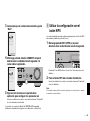
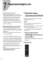
This document explains 5.1-channel system setup, 5.1.2-channel system
setup using the front presence speakers, and unit configuration, followed by
step-by-step instructions. Basic operations, such as playing Blu-ray Discs,
DVDs, and radio content, are also explained.
The unit is equipped with a number of other functions not described in this
booklet. For more information about this product, refer to the Owner’s Manual
included on the supplied CD-ROM. The latest Owner’s Manual can be
downloaded from the following website.
http://download.yamaha.com/
[For U.S. customers only]
Visit the following website for additional information, FAQ’s, downloads such
as “Owner’s Manual” and product updates.
http://usa.yamaha.com/support/
AV SETUP GUIDE
AV SETUP GUIDE is an app that guides you
through the process of connecting a TV or playback
device, such as a BD/DVD or CD player, and
speakers to the AV receiver. Search “AV SETUP
GUIDE” on the App Store or Google Play for
details.

En 7
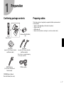
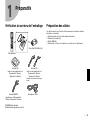
1
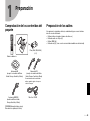
Preparation
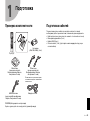
Confirming package contents Preparing cables
The following cables (not supplied) are required to build the system described
in this document.
• Speaker cables (depending on the number of speakers)
• Audio pin cable (x1)
• HDMI cables (x3)
• Network cable (x1) (when connecting to a router via a network cable)
Remote control
Batteries (AAA, R03, UM-4)
(x2)
AM antenna
(except for U.K., Europe, Australia
and Russia models)
FM antenna
(except for U.K., Europe, Australia
and Russia models)
CD-ROM (Owner’s Manual)
Quick Start Guide (this booklet)
YPAO microphone
One of the above is supplied depending
on the region of purchase.
DAB/FM antenna
(U.K., Europe, Australia and
Russia models)

8 En
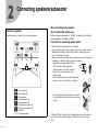
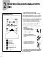
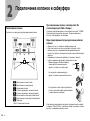
2
Connecting speakers/subwoofer
When connecting 6-ohm speakers
(U.S.A. and Canada models only)
Set the unit’s speaker impedance to “6 Ω MIN”. For details, see “Setting the
speaker impedance” in the Owner’s Manual.
Precautions for connecting speaker cables
• Be sure that the unit and subwoofer are turned off.
• Prepare speaker cables in a place away from the unit, to avoid accidentally
dropping wire strands into the unit's interior which could result in a short
circuit or malfunction of the unit.
• Improper connection of speaker cables could cause a short circuit resulting
in damage to, or malfunctioning of, the unit or speakers.
– Carefully remove approximately 10 mm
(3/8") of insulation from the speaker-
connection ends of the cables, and twist
the bare wires of each speaker cable
together firmly.
– Do not allow the bare wires of separate speaker
cables to come into contact with one another.
– Do not allow speaker cable bare wires to come into
contact with metal parts on the unit (rear panel and
screws).
If “Check SP Wires” is shown on the front display when the unit is turned on,
turn off the unit and be sure that speaker cables have not caused a short
circuit.
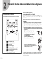
Positioning speakers
Use the diagram as a reference for positioning speakers.
1 Front speaker (L)
2 Front speaker (R)
3 Center speaker
4 Surround speaker (L)
5 Surround speaker (R)
E Front presence speaker (L)*
R Front presence speaker (R)*
9 Subwoofer
* For 5.1.2-channel system
5
4
21
3
9
ER
**
10° to 30° 10° to 30°
10 mm
(3/8")

En 9
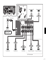
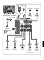
SPEAKERS
2
34
1
9
Subwoofer
2
Front speaker (R)
10 mm
(3/8")
1
Front speaker (L)
3
Center speaker
Surround speaker (R)
5
Surround speaker (L)
4
Use a subwoofer equipped
with built-in amplifier.
Audio pin cable
R
Front presence speaker (R)
E
Front presence speaker (L)
For 5.1.2-channel system

10 En
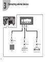
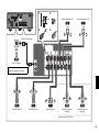
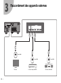
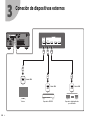
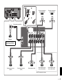
3
Connecting external devices
HDMI
HDMI HDMI
(BD/DVD)
2
3
1
HDMI
(HDCP2.2)
4
(HDCP2.2)
ARC
HDMI OUT
HDMI HDMI HDMI
HDMI
HDMI
HDMI
TV BD/DVD player Satellite/cable set top box
HDMI input
HDMI output HDMI output

En 11
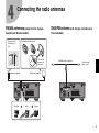
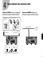
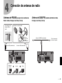
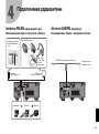
4
Connecting the radio antennas
FM/AM antennas (except for U.K., Europe,
Australia and Russia models)
DAB/FM antenna (U.K., Europe, Australia and
Russia models)
FM antenna (supplied) AM antenna (supplied)
Hold down Insert Release
Assembling the AM antenna
Place the AM
antenna on a
flat surface.
Fix the end of the
FM antenna to a
wall.
DAB/FM antenna (supplied)
Fix the antenna
ends to a wall.

12 En
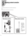
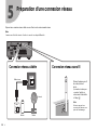
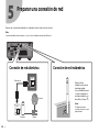
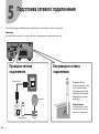
5
Preparing a network connection
Prepare a wired or wireless network connection in accordance with your network environment.
Note
The wireless antenna must be raised if the unit will be connected to a Bluetooth device.
LAN
Internet
Network cable
Router Modem
Wired network connection
Raise the wireless
antenna so that it is
standing up straight.
(Procedures for
connecting the unit to a
wireless router are
described in step
7
.)
Notice
Do not apply excessive force
on the antenna. Doing so
may damage it.
Wireless network connection

En 13
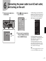
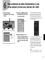
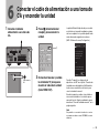
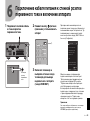
6
Connecting the power cable to an AC wall outlet,
and turning on the unit
1 Plug the power cable into an
AC wall outlet.
2 Press z (receiver power) to
turn on the unit.
3 Turn on the TV and switch the
TV input to display video from
the unit (HDMI OUT jack).
The Network Setup screen shown below will be
displayed on the TV when the unit is turned on for
the first time after purchase. It may take several
tens of seconds for the screen to be displayed
(WAC: Wireless Accessory Configuration).
See “Sharing the iOS device setting” under
“Connecting the unit to a wireless network” in the
Owner’s Manual when using this function to
connect the unit to a network.
This document explains wireless connection
using methods other than this function. Follow
the procedure described under “Connecting the
unit to a network” on the next page.
Note
This screen will not be displayed if the unit is connected
to a router via its NETWORK jack (wired connection).
To an AC wall
outlet
HDMI
123 4
SLEEP
ONE
B
H
DMI
1
2
3
4
S
LEEP
ONE
B
z
CANCEL
RETURN
Network Setup WAC
You can share the network’s
wireless (Wi-Fi) setting with
this device using a device
with iOS7 or later.
↓ NEXT
To perform network setup using
another method, press ENTER.
Language <English>

14 En
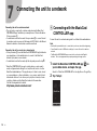
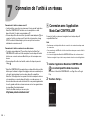
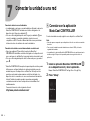
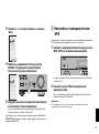
7
Connecting the unit to a network
Connecting the unit to a wireless network
• The unit can be connected to a wireless network using the MusicCast
CONTROLLER app* installed on your smartphone or other mobile device.
Follow procedure
A .
• If a mobile device will not be used, follow procedure
B to connect the unit
to a wireless router (access point) that supports WPS. Refer to the Owner’s
Manual for details on other wireless connection methods.
Connecting the unit to a router via a network cable
• Follow procedure
A to use the MusicCast CONTROLLER app* installed on
your smartphone or other mobile device to connect to the MusicCast
network to play music over a network.
• If a mobile device will not be used, skip this step and proceed to step
8
.
* MusicCast CONTROLLER, an app for mobile devices, can be used to
easily configure network settings for not only this unit, but also for other
MusicCast-enabled devices. This app allows you to listen to music stored
on your smartphone or other mobile device, or on servers, and to listen to
Internet radio stations. It also allows you to play this rich variety of music
content on all devices in the MusicCast network at the same time.
Visit the following website for details.
http://www.yamaha.com/musiccast/
A Connecting with the MusicCast
CONTROLLER app
Connect the unit to a network and register it as a MusicCast-enabled device.
Note
• Confirm that your mobile device is connected to your home router before beginning.
• You will need the router’s SSID and security key to connect the unit to a wireless
network.
• The MusicCast CONTROLLER app screens in this section show the English
interface. The screen appearance may vary depending on the app version.
1 Install the MusicCast CONTROLLER app on
your mobile device, and open the app.
Search for “MusicCast CONTROLLER” on the App Store or Google Play.
2 Tap “Setup”.

En 15
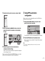
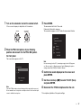
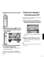
3 Confirm that the unit is turned on, and tap “Next”.
4 Press and hold the CONNECT button on the front
panel of the unit for 5 seconds, as instructed by
the app.
5 Follow the app’s on-screen instructions to
configure network settings.
When a connection has been established, “Completed” will be displayed
in the front display of the unit.
Network connection with the MusicCast CONTROLLER app is now complete,
and the unit has been registered as a MusicCast-enabled device.
B Using WPS push-button
configuration
Wireless connection can be configured with one push of the WPS button on
the wireless router (access point).
1 Press and hold INFO (WPS) on the unit’s front
panel for more than 3 seconds.
“Press WPS button on Access Point” will be displayed in the front display.
2 Push the WPS button on the wireless router.
When a connection has been established, “Completed” will be displayed
in the front display.
Note
If “Not connected” is displayed, repeat the process from step 1 or try another
connection method.
PROGRAM
STRAIGHT
(CONNECT)
AUX U SB
AUDIO
5V 1A
SCENE
TV
NET
RADIO
SCENE
YPAO MIC
INPUT
TVBD/DVD
NE
T
MEMORY
INFO (WPS)
PRESET
FM

16 En
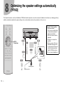
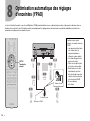
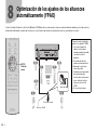
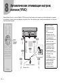
8
Optimizing the speaker settings automatically
(YPAO)
The Yamaha Parametric room Acoustic Optimizer (YPAO) function detects speaker connections, measures the distances from them to your listening position(s),
and then automatically optimizes the speaker settings, such as volume balance and acoustic parameters, to suit your room.
12
3
9
54
ER
STRAIGHT DIRECT ENHANCER BASS
ENTER
TOP MENU
PROGRAM VOLUME
POP-UP/MENU
TUNING PRESET
HOME
MEMORY
DISPLAY
RETURN
BLUE
YELLOWGREEN
RED
S
TRAI
GH
T
D
IRE
C
T
E
NHAN
CE
R
BA
SS
T
O
P MEN
U
PR
OG
RAM
V
O
L
U
ME
POP-UP/MENU
TU
NIN
G
PRESE
T
H
O
ME
M
EMORY
D
I
S
PLAY
RETURN
B
LUE
Y
E
L
L
O
LL
W
O
O
G
RE
E
N
R
E
D
ENTER
Note the following regarding
YPAO measurement
• Test tones are output at high
volume and may surprise or
frighten small children.
• Test tone volume cannot be
adjusted.
• Keep the room as quiet as
possible.
• Stay in a corner of the room
behind the listening position
so that you do not become an
obstacle between speakers
and the YPAO microphone.
• Do not connect headphones.
Ear height
Listening position
YPAO microphone
Cursor keys

En 17
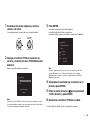
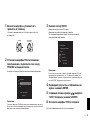
1 Turn on the subwoofer and set the volume to half.
If the crossover frequency is adjustable, set it to maximum.
2 Place the YPAO microphone at your listening
position and connect it to the YPAO MIC jack on
the front panel.
The screen below appears on the TV.
Note
Place the YPAO microphone at your listening position (same height as your ears).
We recommend the use of a tripod as a microphone stand. You can use the tripod
screws to stabilize the microphone.
3 Press ENTER.
The measurement will start in 10 seconds.
It takes about 3 minutes to measure.
The screen below appears on the TV when the measurement finishes.
Note
If an error message (such as E-1) or warning message (such as W-2) appears,
see “Error messages” or “Warning messages” under “Optimizing the speaker
settings automatically (YPAO)” in the Owner’s Manual.
4 Confirm the results displayed on the screen and
press ENTER.
5 Use the cursor keys (e/r) to select “SAVE” (Save)
and press ENTER.
6 Disconnect the YPAO microphone from the unit.
This completes optimization of the speaker settings.
VOLUME
CROSSOVER/
HIGH CUT
MIN MAX
MIN MAX
Auto Setup
Start
Exit
Power Amp Assign
Presence
Auto Setup
Measurement Finished
Result
3/2/0.1ch
3.0/10.5m
-3.0/+10.0dB
OK : ENTER

18 En
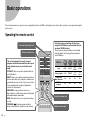
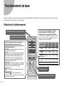
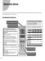
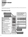
Basic operations
This section describes basic operations such as playing Blu-ray Discs and DVDs, and tuning into radio stations. Most operations can be performed using the
remote control.
Operating the remote control
STRAIGHT DIRECT ENHANCER BASS
TOP MENU
MUTE
PROGRAM VOLUME
POP-UP/MENU
AM
FM
SCENE
BD
DVD
TV
NET
RADIO
HDMI
AUDIO
AV
1 2 3
BLUETOOTH
USB
123
123 4
NET
AUX
SLEEP
ZONE
A
ZONE
B
U
POP-UP/MENU
SLEEP
Z
O
N
E
A
Z
ONE
B
The unit is equipped with a variety of sound
programs and surround decoders that allow you to
enjoy playback sources in your favorite sound
mode.
STRAIGHT: Input sources will be played without any
sound field effects.
DIRECT: Input sources will be played using only those
functions absolutely vital to playback to minimize noise
generated by electronic circuitry. Functions such as the
front panel display will be temporarily disabled to
achieve Hi-Fi sound quality.
ENHANCER: Compressed music stored on a
Bluetooth device or USB storage device will be played
with additional depth and breadth.
BASS: Extra bass allows you to enjoy enhanced bass
sounds.
PROGRAM (e/r): Sound programs suitable for
movies, music and stereo playback can be selected.
Unit input sources and settings that have been
assigned to SCENE keys can be selected with just
one touch (SCENE function).
The unit turns on automatically when it is in standby
mode. By default, the following settings assigned to
each SCENE key.
SCENE key
Input HDMI1 AUDIO1
NET
RADIO
TUNER
Sound program Sci-Fi
STRAIGHT
7ch
Stereo
7ch
Stereo
Compressed
Music Enhancer
Off On On On
SCENE link
playback
On On Off Off
Target zone Zone A Zone A Zone A Zone A
BD
DVD
TV
NET
RADIO
Adjust the volume level
Select an input source
Turn on/off (standby) the unit
Mute the audio output

En 19
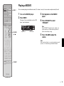
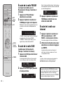
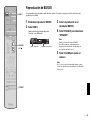
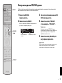
Playing a BD/DVD
We recommend playing back multichannel audio (5.1-channel or more) to feel surround sound produced by the unit.
1 Turn on the BD/DVD player.
2 Press HDMI 1.
The name of the connected device such as “BD
player” may be displayed.
3 Start playback on the BD/DVD
player.
4 Press STRAIGHT to select
“STRAIGHT”.
Note
When “STRAIGHT” (straight decode) is enabled, each
speaker produces each channel audio signal directly
(without sound field processing).
5 Press VOLUME to adjust the
volume.
Note
When sound is not heard, or no sound is output from a specific
speaker, see “Troubleshooting” in the Owner’s Manual.
MUTE
ENHANCER
STEREO
TUNED
SLEEP
ECO
CHARGE
ADAPTIVE DRC
VIRTUAL
BD Player
VOL.
OUT
Input source Device name
STRAIGHT DIRECT ENHANCER BASS
TOP MENU
PROGRAM VOLUME
POP-UP/MENU
SCENE
RADIO
HDMI
123 4
TUNING PRESET
HOME
MEMORY
BLUE
YELLOWGREEN
RED
SLEEP
ONE
B
D
IREC
T
E
NHANCER BASS
T
O
P MEN
U
PR
OG
RAM
POP-UP/MENU
S
CEN
E
R
ADI
O
H
DMI
2
3
4
TU
NIN
G
PRESE
T
H
O
ME
M
EM
O
RY
BLUE
Y
E
L
L
O
L
L
W
O
O
G
RE
E
N
R
E
D
S
LEEP
O
N
E
B
VOLUME
( / )
HDMI 1
STRAIGHT

20 En
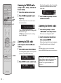
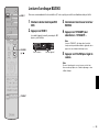
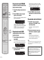
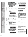
Listening to FM/AM radio
(except for U.K., Europe, Australia and
Russia models)
1 Press FM or AM to select a band.
2 Press TUNING repeatedly to set a
frequency.
Hold down the key for about a second to search
stations automatically.
“TUNED” lights up when the unit is receiving an FM/
AM radio station signal.
“STEREO” lights up when the unit is receiving a
stereo FM radio signal.
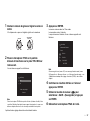
Listening to DAB radio
(U.K., Europe, Australia and Russia
models)
1 Press DAB to select the DAB band.
The following message appears on the front panel if
you have not performed an initial scan yet.
2 Press ENTER to start an initial scan.
When the initial scan finishes, the unit automatically
tunes into the first DAB radio station as stored in
station order.
3 Press TUNING repeatedly to select
a DAB radio station.
Listening to Internet radio
1 Press NET repeatedly to select
“NET RADIO” as the input source.
The browse screen is displayed on the TV.
2 Use the cursor keys to select an
item and press ENTER.
When an Internet radio station is selected, playback
starts and the playback screen is displayed.
Note
Internet radio stations can also be selected using the
MusicCast CONTROLLER app installed on your mobile device.
ENHANCER
LINK
ECO
MASTER
OUT
2
-
R
es
Hi
YPAO
VOL.
A
-
DRC
SLEEP
PARTY
ZONE
A2B3
FPR
SBL SB SBR
FPL
MUTE VIRTUAL
VOL.
SL
SW
SR
STEREO
TUNED
FM 98.50MHz
ENHANCER
LINK
ECO
MASTER
OUT
2
-
R
es
Hi
YPAO
VOL.
A
-
DRC
SLEEP
PARTY
ZONE
A2B3
MUTE VIRTUAL
SBL SB SBR
FPRFPL
SL
SW
SR
STEREO
TUNED
VOL.
Press [ENTER]
ENHANCER
LINK
ECO
MASTER
OUT
2
-
R
es
Hi
YPAO
VOL.
A
-
DRC
SLEEP
PARTY
ZONE
A2B3
MUTE VIRTUAL
SBL SB SBR
FPRFPL
SL
SW
SR
STEREO
TUNED
VOL.
>>>------- 30%
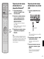
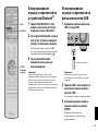
The MusicCast CONTROLLER app installed on
your mobile device can be used to play music from
streaming services. Refer to documentation
included on the supplied CD-ROM for more
information.
ENHANCER
LINK
ECO
MASTER
OUT
2
-
R
es
Hi
YPAO
VOL.
A
-
DRC
SLEEP
PARTY
ZONE
A2B3
MUTE VIRTUAL
SBL SB SBR
FPRFPL
STEREO
TUNED
VOL.
SL
SW
SR
BBC Radio 4
STRAIGHT DIRECT ENHANCER BASS
ENTER
TOP MENU
PROGRAM VOLUME
POP-UP/MENU
AM
FM
SCENE
BD
HDMI
USB
2 3
123 4
NET
AUX
TUNING PRESET
HOME
MEMORY
DISPLAY
RETURN
BLUE
YELLOWGREEN
RED
SLEEP
ZONE
A
ZONE
B
STRAIG
H
T
D
IREC
T
ENHANCE
R
B
AS
S
T
O
P MEN
U
PR
OG
RAM
V
O
L
U
M
E
P
O
P-UP
/
MENU
S
CEN
E
BD
H
DMI
US
B
2
3
1
2
3
4
AUX
PRESET
H
O
ME
MEM
O
R
Y
DI
S
PLAY
RET
U
RN
BLUE
Y
E
L
L
O
L
L
W
O
O
G
RE
E
N
R
E
D
S
LEEP
Z
O
N
E
A
Z
O
N
E
B
FM
NET
TUNING
ENTER
Cursor
keys
AM or
DAB
La pagina si sta caricando...
La pagina si sta caricando...
La pagina si sta caricando...
La pagina si sta caricando...
La pagina si sta caricando...
La pagina si sta caricando...
La pagina si sta caricando...
La pagina si sta caricando...
La pagina si sta caricando...
La pagina si sta caricando...
La pagina si sta caricando...
La pagina si sta caricando...
La pagina si sta caricando...
La pagina si sta caricando...
La pagina si sta caricando...
La pagina si sta caricando...
La pagina si sta caricando...
La pagina si sta caricando...
La pagina si sta caricando...
La pagina si sta caricando...
La pagina si sta caricando...
La pagina si sta caricando...
La pagina si sta caricando...
La pagina si sta caricando...
La pagina si sta caricando...
La pagina si sta caricando...
La pagina si sta caricando...
La pagina si sta caricando...
La pagina si sta caricando...
La pagina si sta caricando...
La pagina si sta caricando...
La pagina si sta caricando...
La pagina si sta caricando...
La pagina si sta caricando...
La pagina si sta caricando...
La pagina si sta caricando...
La pagina si sta caricando...
La pagina si sta caricando...
La pagina si sta caricando...
La pagina si sta caricando...
La pagina si sta caricando...
La pagina si sta caricando...
La pagina si sta caricando...
La pagina si sta caricando...
La pagina si sta caricando...
La pagina si sta caricando...
La pagina si sta caricando...
La pagina si sta caricando...
La pagina si sta caricando...
La pagina si sta caricando...
La pagina si sta caricando...
La pagina si sta caricando...
La pagina si sta caricando...
La pagina si sta caricando...
La pagina si sta caricando...
La pagina si sta caricando...
La pagina si sta caricando...
La pagina si sta caricando...
La pagina si sta caricando...
La pagina si sta caricando...
-
 1
1
-
 2
2
-
 3
3
-
 4
4
-
 5
5
-
 6
6
-
 7
7
-
 8
8
-
 9
9
-
 10
10
-
 11
11
-
 12
12
-
 13
13
-
 14
14
-
 15
15
-
 16
16
-
 17
17
-
 18
18
-
 19
19
-
 20
20
-
 21
21
-
 22
22
-
 23
23
-
 24
24
-
 25
25
-
 26
26
-
 27
27
-
 28
28
-
 29
29
-
 30
30
-
 31
31
-
 32
32
-
 33
33
-
 34
34
-
 35
35
-
 36
36
-
 37
37
-
 38
38
-
 39
39
-
 40
40
-
 41
41
-
 42
42
-
 43
43
-
 44
44
-
 45
45
-
 46
46
-
 47
47
-
 48
48
-
 49
49
-
 50
50
-
 51
51
-
 52
52
-
 53
53
-
 54
54
-
 55
55
-
 56
56
-
 57
57
-
 58
58
-
 59
59
-
 60
60
-
 61
61
-
 62
62
-
 63
63
-
 64
64
-
 65
65
-
 66
66
-
 67
67
-
 68
68
-
 69
69
-
 70
70
-
 71
71
-
 72
72
-
 73
73
-
 74
74
-
 75
75
-
 76
76
-
 77
77
-
 78
78
-
 79
79
-
 80
80


Yamaha RX-A670 Guida utente
- Categoria
- Radio
- Tipo
- Guida utente
in altre lingue
- English: Yamaha RX-A670 User guide
- français: Yamaha RX-A670 Mode d'emploi
- español: Yamaha RX-A670 Guía del usuario
- Deutsch: Yamaha RX-A670 Benutzerhandbuch
- русский: Yamaha RX-A670 Руководство пользователя
- Nederlands: Yamaha RX-A670 Gebruikershandleiding
- dansk: Yamaha RX-A670 Brugervejledning
- svenska: Yamaha RX-A670 Användarguide
- Türkçe: Yamaha RX-A670 Kullanici rehberi
- suomi: Yamaha RX-A670 Käyttöohjeet
Documenti correlati
-
Yamaha RX-S602 Guida Rapida
-
Yamaha RX-A870 Guida Rapida
-
Yamaha HTR-3068 Guida d'installazione
-
Yamaha RX-A2050 Guida d'installazione
-
Yamaha RX-S601 Guida d'installazione
-
Yamaha RX-A1050 Guida d'installazione
-
Yamaha RX-V683 Guida Rapida
-
Yamaha RXV383 Manuale del proprietario
-
Yamaha RX-A1070 Guida Rapida
-
Yamaha RX-A550 Guida d'installazione