
1/10
Divisione della BETA UTENSILI spa Via Volta. 18 - 20845 SOVICO (MB) ITALY Tel. +39.039.20771-Fax + 39.039.2010742
SPECIFICA PRODOTTO
ISTRUZIONI PER L’USO E LA MANUTENZIONE
Informazioni tecniche
Condizioni d’uso previste e limiti operativi
Prescrizioni per gli operatori
Rischi residui
Modalità e frequenza d’ispezioni periodiche d’idoneità
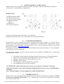
GANCI ACCORCIATORI A FORCELLA IN ACCIAIO LEGATO AD ALTA
RESISTENZA CON SICURA DI BLOCCAGGIO
GRADO 8 / UNI EN 1677 - 1
ARTICOLO 8061R
La lingua originale della presente specifica è quella Italiana.
Sede produttiva Accessori per funi ROBUR
Zona Industriale – C.da S. Nicola
67039 SULMONA (L’AQUILA)
Tel. +39.0864.2504.1 – Fax +39.0864.253132
www.beta-tools.com – [email protected]
R/SP/8061R/02
Data 16/10/2019

2/10
Divisione della BETA UTENSILI spa Via Volta. 18 - 20845 SOVICO (MB) ITALY Tel. +39.039.20771-Fax + 39.039.2010742
1) CARATTERISTICHE TECNICHE
Materiale:
Gancio Acciaio da bonifica
Trattamento Termico:
Bonifica
Norme di riferimento:
Gancio UNI EN 1677-1
Materiali e requisiti UNI EN 1677-1
Trattamento Superficiale:
Gancio - Verniciatura epossidica Arancio (RAL 2004 o
RAL 2011)
Il collaudo viene eseguito in base a specifiche e regole interne in riferimento alla norma UNI EN ISO
9001.
L’articolo è conforme alla Direttiva Macchine 2006/42/CE.

3/10
Divisione della BETA UTENSILI spa Via Volta. 18 - 20845 SOVICO (MB) ITALY Tel. +39.039.20771-Fax + 39.039.2010742
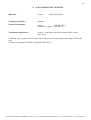
CARATTERISTICHE DIMENSIONALI:
Tabella “A”
CATENA
WLL
kg
A B E F
G1
H L M P
U1
g
CODICE
6 1120
8 34.6
8 20
8 18.5
76
12 26
23 160 80610211
7-8 2000
9.5
39.4
10.8
22
9 18.5
88
13 32
24 400 80610220
10 3150
12.5
46 13.5
29
13
29.5
124
15.6
44
31.5
840 80610231
13 5300
15 52 17 37
16
42 160
19 57
40 1630 80610253
Le quote indicate sono espresse in mm.
WLL= CARICO MASSIMO DI ESERCIZIO
COEFFICIENTE DI SICUREZZA: 4
NB: il carico di lavoro indicato in tabella è applicabile quando la direzione della forza agente sul
gancio è coincidente all'asse del gancio stesso.
ATTENZIONE: il coefficiente di sicurezza è soltanto un’indicazione per la sicurezza del prodotto.
Non si devono mai superare i carichi (WLL) indicati nella tabella.

4/10
Divisione della BETA UTENSILI spa Via Volta. 18 - 20845 SOVICO (MB) ITALY Tel. +39.039.20771-Fax + 39.039.2010742
Definizioni:
• Carico massimo di esercizio (WLL): è il carico massimo che l’articolo può sopportare (lungo l’asse
principale se non diversamente indicato) in condizioni di utilizzo.
•
Coefficiente di sicurezza:
è il rapporto tra il carico di rottura minimo garantito e il carico limite di
lavoro.
• Ispezione: Controllo visivo relativo allo stato del gancio per individuare evidenti danneggiamenti o
usure che possono alterarne l’utilizzo.
• Esame accurato: Esame visivo effettuato da una persona competente e, se necessario, coadiuvato da
altri mezzi, quali i controlli non-distruttivi, al fine di individuare danneggiamenti o usure che possono
alterare l’utilizzo del componente.
• Persona competente: Persona designata, istruita correttamente, qualificata per conoscenza e
esperienza pratica; che ha ricevuto le istruzioni necessarie per seguire le prove e gli esami richiesti.
2) SPECIFICHE DI COLLAUDO
L’accessorio è sottoposto ad una serie di severi controlli a per accertarne la funzionalità prestazionale e
la rispondenza alle specifiche.
La numerosità dei campioni e i relativi piani di campionamento, sono scelti in funzione della
caratteristica da verificare in accordo e per quanto previsto dalla norma UNI ISO 2859/1, ed i risultati
archiviati nell’ufficio qualità dello stabilimento di Sulmona.
2.A Controllo dimensionale
Verifica che le dimensioni dell’articolo rientrino nelle tolleranze stabilite dai relativi
disegni di costruzione interni.
2.B Controllo visivo
Verifica la presenza di eventuali imperfezioni dovute a stampaggio, lavorazione
meccanica, rivestimento superficiale e rispondenza della marcatura a disegni di fase
interni.
2.C Analisi chimica
Verifica la rispondenza della composizione chimica del materiale.
2.D Analisi metallografica
Verifica il processo di bonifica: a 500 ingrandimenti si deve riscontrare una
distribuzione omogenea di martensite rinvenuta.
2.E Prove di trazione
Verifica che l’accessorio sottoposto ad una trazione, arrivi a rottura, dopo che la forza
applicata, abbia almeno superato il carico di lavoro moltiplicato per il coefficiente di
sicurezza. La prova è eseguita in accordo con la norma UNI 10002/1.
2.F Prova di fatica
Verifica che l’articolo, sottoposto a trazione per 20.000 cicli con un carico di 1,5 volte
il “WLL” indicato nella tabella A, non subisca rotture.
2.G Prova di fabbricazione
Consiste nel provare ogni singolo articolo ad un carico pari a 2,5 volte il “WLL”
indicato nella tabella A, in conformità alla norma UNI EN 1677-1.
2.H Prova di durezza
Verifica che la durezza dell’articolo rientri nei valori stabiliti dai relativi disegni di
costruzione interni.

5/10
Divisione della BETA UTENSILI spa Via Volta. 18 - 20845 SOVICO (MB) ITALY Tel. +39.039.20771-Fax + 39.039.2010742
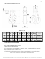
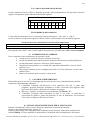
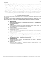
3) COME LEGGERE LA MARCATURA
:
Sull’accessorio sono stampate in maniera indelebile marcature e sigle che identificano il prodotto e
definiscono le caratteristiche e le applicazioni.
MARCATURA
1) Misura catena in pollici
2) Misura catena in mm.
3) Codice di rintracciabilità
4) Marchio produttore
(Robur)
5) Marchio CE
6) Grado del materiale
(Fig. 1)
La posizione della marcatura sul disegno è solo indicativa.
Realmente le posizioni delle varie voci possono trovarsi in punti differenti.
4) AVVERTENZE GENERALI.
Il manuale deve essere custodito da persona responsabile allo scopo preposta, in un luogo idoneo,
affinché esso risulti sempre disponibile per la consultazione nel miglior stato di conservazione. In caso
di smarrimento o deterioramento, la documentazione dovrà essere prontamente sostituita scaricandola
dal sito del costruttore:
www.beta-tools.com
Il costruttore si riserva la proprietà materiale ed intellettuale del presente manuale e ne vieta la modifica,
anche parziale, per fini commerciali.
Con riferimento a quanto riportato in queste istruzioni d’uso la BETA UTENSILI S.P.A. declina ogni
responsabilità in caso di:
• Uso degli accessori contrario alle leggi nazionali sulla sicurezza e sull’antinfortunistica.
• Errata scelta o predisposizione dell’apparecchio con il quale saranno connessi.
• Mancata o errata osservanza delle istruzioni per l’uso.
• Modifiche agli accessori.
• Uso improprio e omessa manutenzione ordinaria.
• Uso combinato ad accessori non conformi.
ATTENZIONE
!
: I dati di marcatura non devono essere rimossi con molature o abrasioni,
(neanche accidentali, i ganci senza riferimenti di identificazione devono essere resi inutilizzabili e
rottamati).
Non è consentito apporre caratteri aggiuntivi a quelli di fabbricazione.
5) CRITERI DI SCELTA
Il gancio deve essere impiegato come componente di accessorio di sollevamento assemblato in brache
di catena in conformità alla EN 818-4, ed i parametri che devono essere attentamente considerati
nella scelta dei ganci sono:

6/10
Divisione della BETA UTENSILI spa Via Volta. 18 - 20845 SOVICO (MB) ITALY Tel. +39.039.20771-Fax + 39.039.2010742
5.A
CARICO MASSIMO DI ESERCIZIO
Il carico massimo di lavoro (WLL) è funzione del grado e della configurazione
,
che per brache a braccio
singolo corrisponde a quanto indicato nella tabella seguente:
Carico massimo di lavoro
WLL
Diametro della catena grado 8
(mm)
6 7 8 10 13 16 20 22 26 32
t
1,12 1,5 2 3,15 5,3 8 12.5 15 21,2 31,5
5.B
TEMPERATURE D’IMPIEGO
L’intervallo di temperatura in cui è consentito l’impiego del gancio va da –40°C a +400°C.
In caso di utilizzo a temperature superiori ridurre il carico in percentuale come da tabella seguente.
Variazione del carico massimo di esercizio con la temperatura
Temperatura t °C
-40<t≤200 200<t≤300
300=<t≤400
Carico di esercizio espresso come percentuale del carico massimo di esercizio
100 90 75
Non superare mai i 400°C, oltre i quali il gancio non può essere più utilizzato
,
e deve essere rottamato.
6) CONDIZIONI NON AMMESSE
Non è consentita la movimentazione dei seguenti carichi:
• Aventi un peso superiore al carico massimo di esercizio.
• Aventi una struttura non sufficientemente resistente alla trazione esercitata dalla presa.
• Aventi temperature superiori o inferiori a quelle ammesse.
• Classificati come pericolosi, (es. metalli fusi, materiali infiammabili, corrosivi, fissili,
esplosivi, ecc.).
• Che possono cambiare la loro configurazione statica e/o il loro baricentro o il loro stato
chimico fisico.
• Immersi in soluzioni acide o esposti a vapori acidi.
7) CONTROLLI PRELIMINARI
Prima della messa in servizio e/o montaggio gli accessori devono essere controllati da una persona
competente adeguatamente addestrata.
• Controllare l’integrità dell’accessorio ed in particolare che non vi siano tagli,
piegature, incisioni, abrasioni, incrinature o cricche, corrosioni, bave taglienti, usure
provocate dall’utilizzo o difetti dovuti a cattivo stoccaggio.
• Rilevare e registrare le dimensioni con riferimento alla tabella “A”.
• Controllare l’integrità della marcatura in tutte le sue parti, in particolare le
prescrizioni di portata e grado del materiale, al fine di identificare con precisione
l’accessorio in funzione del carico di lavoro.
8) INSTALLAZIONE ISTRUZIONI PER IL MONTAGGIO
Durante l’installazione dell’accessorio indossare i dispositivi di protezione adeguati:
guanti, scarpe antinfortunistiche, elmetto, etc.
Il gancio self locking viene impiegato come componete di un sistema d’imbracatura conforme alla
norma EN818-4. Il carico massimo di utilizzazione è in funzione della configurazione del sistema.

7/10
Divisione della BETA UTENSILI spa Via Volta. 18 - 20845 SOVICO (MB) ITALY Tel. +39.039.20771-Fax + 39.039.2010742
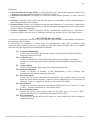
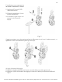
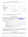
L’installazione come componente in
un sistema d’imbracatura si effettua:
1. Introducendo l’estremità della
catena nella forcella.
2. Spingendo manualmente il perno
nel foro della forcella.
3. Incastrando la spina elastica con i
necessari colpi di martello.
(Fig. 2)
Fig. 2
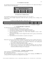
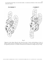
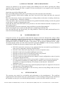
il gancio accorciatore serve ad accorciare un braccio della catena nei casi in cui si renda necessario, es:
equilibrare il carico. Non utilizzare il gancio per altri scopi.
Fig.3
4. Aprire il sistema di bloccaggio;
5. Stabilire la lunghezza del braccio ed inserire un anello della catena nella apposita sede;
6. Rilasciare il perno del sistema di bloccaggio per evitare che l’anello possa fuoriuscire dalla sede.
(fig.3).

8/10
Divisione della BETA UTENSILI spa Via Volta. 18 - 20845 SOVICO (MB) ITALY Tel. +39.039.20771-Fax + 39.039.2010742
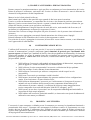
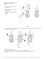
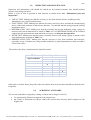
L’anello della catena deve poggiare completamente sulla sella del gancio, è assolutamente vietato
sollevare il carico con la punta del gancio (Fig.4)
ERRATO CORRETTO
Fig.4
Mettere in tensione la catena senza sollevare, controllare il baricentro e la distribuzione delle forze.
Considerare che nel caso di sollevamento di carichi squilibrati con due tiranti, il peso maggiore è sempre
sostenuto dal tirante più corto. Adottare gli accorgimenti più idonei per riequilibrare il carico in funzione
della tipologia di imbracatura.

9/10
Divisione della BETA UTENSILI spa Via Volta. 18 - 20845 SOVICO (MB) ITALY Tel. +39.039.20771-Fax + 39.039.2010742
9) USO DELL’ACCESSORIO - PRESA E MANOVRA
Prestare sempre la massima attenzione a ogni specifico avvertimento per la movimentazione del carico.
Prima di azionare il sollevatore, assicurarsi che il carico sia libero di muoversi e non sia bloccato da
elementi di collegamento o da altri impedimenti.
Mettere in tiro le funi prima di sollevare.
Stare lontani con le mani o altre parti del corpo quando le funi sono poste in tensione.
Il carico va sollevato lentamente, va controllato che sia sicuro e che assuma la posizione preventivata.
Muovere il carico con movimenti lenti, lineari e costanti, evitando brusche accelerate o frenate che, per
effetto dell’inerzia, possono creare pericolose oscillazioni.
Predisporre anticipatamente il luogo di deposito al suolo del carico, assicurandosi che il terreno (o il
pavimento) sia adeguatamente resistente per sopportare il carico.
Assicurarsi che l’accesso al luogo di deposito sia privo di ostacoli e che le persone siano a distanza di
sicurezza.
Il carico deve essere appoggiato con cautela facendo attenzione che la braca non si impigli.
Prima di allentare le funi controllare che il carico sia ben supportato e stabile.
Una volta che il carico è appoggiato in sicurezza, la braca deve essere rimossa a mano, e mai allontanata
con l’apparecchio di sollevamento.
10) CONTROINDICAZIONI D’USO
L’utilizzo dell’accessorio per scopi non previsti, il suo uso in condizioni estremamente pericolose, la
carenza di manutenzione, possono comportare gravi situazioni di pericolo per l’incolumità delle
persone esposte e di danno per l’ambiente di lavoro, oltre che pregiudicare la funzionalità e la sicurezza
effettiva del prodotto. Le azioni di seguito citate che ovviamente non possono coprire l’intero arco di
potenziali possibilità di “cattivo uso” dell’accessorio, costituiscono tuttavia quelle “ragionevolmente”
più prevedibili. Quindi:
• NON utilizzare l’accessorio collegandolo ad apparecchiature di dimensioni, temperatura,
punto d’aggancio e forma non idonei alle sue caratteristiche.
• NON sollevare il carico sottoponendo l’accessorio a sollecitazioni di tipo pulsante.
• NON fare oscillare il carico durante la movimentazione.
•
NON utilizzare l’accessorio per sollevare e trasportare carichi sospesi in volo
(aeromobili);
• NON usare l’accessorio per trazionare carichi vincolati.
• NON mettere in tensione apparecchiature che possono cambiare la loro configurazione
statica, il loro baricentro o lo stato chimico-fisico.
• NON utilizzare direttamente l’accessorio per il sollevamento o il trasporto di persone o
animali; nel caso di utilizzo dell’accessorio come componente di macchine per il
sollevamento di persone o animali, i coefficienti di sicurezza vanno maggiorati da un
tecnico competente in accordo alla direttiva 2006/42/CE, allegato I, par.6”.
• NON operare in aree dove è prescritto l’uso di componenti antideflagranti/antiscintilla o
in presenza di forti campi magnetici.
• NON saldare sull’accessorio particolari metallici, ne intervenire con riporti di saldatura od
utilizzarlo come massa per saldatrici.
11) IDONEITA’ ALL’UTILIZZO
L’accessorio è stato sottoposto a collaudo presso il costruttore per accertare la rispondenza funzionale e
prestazionale dello stesso. L’attestato che accompagna la fornitura certifica il superamento con esito
positivo dei test di collaudo. L’utilizzatore deve eseguire in ogni caso, prima di iniziare ad operare la
verifica della rispondenza funzionale e prestazionale dell’accessorio installato per confermare l’idoneità
all’impiego dell’intera installazione.

10/10
Divisione della BETA UTENSILI spa Via Volta. 18 - 20845 SOVICO (MB) ITALY Tel. +39.039.20771-Fax + 39.039.2010742
12) ISPEZIONE E MANUTENZIONE
Comprende una serie di operazioni eseguite da personale competente istruito allo scopo, relativi a
controlli ed esami accurati durante l’impiego.
Di seguito l’elenco dei controlli da effettuare con cadenze indicate nella tabella “interventi di
manutenzione e controllo”.
• VISIVO: verificare l’assenza di difetti superficiali quali cricche, incisioni, tagli o fessure, abrasioni.
• FUNZIONALE: verificare che l’accessorio possano muoversi liberamente e che il dispositivo di
chiusura dell’imbocco del gancio svolga la funzione antisgancio, in particolare che la molla
mantenga attivo il meccanismo di blocco.
• DEFORMAZIONE: verificare che l’accessorio non sia deformato misurando con un calibro le
dimensioni critiche come indicato nella tabella “A”. NON sono tollerate deformazioni rispetto alle
quote rilevate alla prima messa in servizio.
• USURA: verificare che i punti di contatto non siano usurati misurando con un calibro le dimensioni
critiche indicate nella tabella “A”.
• STATO DI CONSERVAZIONE: verificare l’assenza di ossidazione e corrosione soprattutto in caso
di utilizzo all’aperto; verificare l’assenza di cricche con metodi idonei (es. liquidi penetranti).
Le registrazioni di questi controlli devono essere conservate.
Nel caso in cui il gancio sia sottoposto ad un utilizzo gravoso, è necessario effettuare le verifiche di
usura e stato di conservazione con maggiore frequenza.
13) DEMOLIZIONE E ROTTAMAZIONE DELL’ACCESSORIO
L’accessorio deve essere demolito mediante taglio, in modo tale che non possa più essere utilizzato in
caso presenti:
• una deformazione permanente rispetto alla misura originale;
• cricche, distorsioni o e se si riscontrano riduzioni di sezioni rispetto alla misura originale.
Ad ogni utilizzo Mese Anno
Controllo visivo gener.
x
Funzionale
x
Deformazione
x
Usura
x
Stato di conservazione
x
Tabella interventi di manutenzione e controllo
Tipo di controllo

1/10
Division of BETA UTENSILI SPA, Via Volta. 18 - 20845 SOVICO (MB) ITALY Tel. +39.039.20771-Fax + 39.039.2010742
PRODUCT SPECIFICATIONS
OPERATING AND MAINTENANCE INSTRUCTIONS
Technical specifications
Operating conditions and limits
Operator’s instructions
Residual risks
How and how often periodical fitness instructions should be conducted
CLEVIS GRAB HOOKS WITH SAFETY LATCH
HIGH-TENSILE ALLOY STEEL
GRADE 8 / UNI EN 1677 - 1
ITEM 8061R
The original language of these specifications is Italian.
Manufacturing site ROBUR wire rope accessories
Zona Industriale – C.da S. Nicola
I-67039 SULMONA (L’AQUILA)
Tel. +39.0864.2504.1 – Fax +39.0864.253132
www.beta-tools.com – [email protected]
R/SP/8061R/02
Date 16/10/2019

2/10
Division of BETA UTENSILI SPA, Via Volta. 18 - 20845 SOVICO (MB) ITALY Tel. +39.039.20771-Fax + 39.039.2010742
1) TECHNICAL SPECIFICATIONS
Material:
Hook Hardened and tempered steel
Heat treatment:
Hardening and tempering
Reference standards:
Hook UNI EN 1677-1
Materials and requirements UNI EN 1677-1
Surface treatment:
Hook – Epoxy paint, orange (RAL 2004 or RAL 2011)
The test is performed on the basis of in-house specifications and rules in accordance with UNI EN ISO
9001.
The item complies with Machine Directive 2006/42/EC.

3/10
Division of BETA UTENSILI SPA, Via Volta. 18 - 20845 SOVICO (MB) ITALY Tel. +39.039.20771-Fax + 39.039.2010742
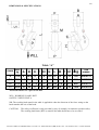
DIMENSIONAL SPECIFICATIONS:
Table “A”
CHAIN
WLL
kg
A B E F
G1
H L M P
U1
g
ITEM
NUMBER
6 1120
8 34.6
8 20
8 18.5
76
12 26
23 160 80610211
7-8 2000
9.5
39.4
10.8
22
9 18.5
88
13 32
24 400 80610220
10 3150
12.5
46 13.5
29
13
29.5
124
15.6
44
31.5
840 80610231
13 5300
15 52 17 37
16
42 160
19 57
40 1630 80610253
All measurements are expressed in mm.
WLL= WORKING LOAD LIMIT
SAFETY COEFFICIENT: 4
NB: The working load stated in the table is applicable when the direction of the force acting on the
hook matches the axis of the hook.
CAUTION: The safety coefficient is only provided by way of example, in relation to product safety.
The working load limits (WLLs) stated in the table should never be exceeded.

4/10
Division of BETA UTENSILI SPA, Via Volta. 18 - 20845 SOVICO (MB) ITALY Tel. +39.039.20771-Fax + 39.039.2010742
Definitions:
• Working load limit (WLL): The maximum load the item can support (along the main axis, if not
otherwise specified) under operating conditions.
•
Safety coefficient:
Guaranteed minimum breaking load to working load limit ratio.
• Inspection: Visual testing of the state of the hook, to check for clear damage or wear which may
affect its use.
• Accurate examination: Visual inspection performed by a trained person, supported, if need be, by
other instruments, including non-destructive testing, to check for damage or wear which may affect
the use of the hook.
• Trained person: A designated, suitably trained person who has proper know-how and practical
expertise and has been given the instructions needed to perform any required tests and examinations.
2) TESTING SPECIFICATIONS
The accessory is subjected to several stringent tests for serviceability, performance and compliance with
specifications.
The number of samples and the related sampling plans are chosen according to the characteristic to test
under UNI ISO 2859/1, and the results are filed in the quality department of the factory in Sulmona.
2.A Dimensional test
Making sure that the dimensions of the item meet such tolerances as established in in-
house working drawings.
2.B Visual test
Testing for defects resulting from forming, mechanical working, surface coating and
correspondence between the marking and in-house drawings.
2.C Chemical analysis
Testing the chemical composition of the material.
2.D Metallographic analysis
Testing the hardening and tempering process: at 500 enlargements, tempered martensite
should be uniformly distributed.
2.E Tensile stress tests
Making sure that the accessory subjected to tensile stress will break, after the applied
force has at least exceeded the working load as multiplied by the safety coefficient. The
test is performed in accordance with UNI 10002/1.
2.F Fatigue test
Making sure that the item subjected to tensile stress for 20,000 cycles with a load 1.5
times as high as the “WLL” stated in Table A will not break.
2.G Manufacturing test
Subjecting each item to a load 2.5 times as high as the “WLL” stated in Table A, in
accordance with UNI EN 1677-1.
2.H Hardness test
Making sure that the hardness of the item lies within the limits established in the
relevant in-house working drawings.

5/10
Division of BETA UTENSILI SPA, Via Volta. 18 - 20845 SOVICO (MB) ITALY Tel. +39.039.20771-Fax + 39.039.2010742
3) HOW TO READ MARKINGS
:
The accessory carries indelible marks and codes which identify the product and define the
specifications and applications.
MARKINGS
1) Chain size in inches
2) Chain size in mm
3) Traceability code
4) Manufacturer’s mark
(Robur)
5) CE mark
6) Material grade
(Fig. 1)
The positions of the markings in the drawing are provided by way of example only.
The various items may actually be found in different positions.
4) GENERAL WARNINGS
The manual should be stored by a trained person, in a suitable place, so that it can always be available
for consultation in the best state of preservation. If the documentation gets lost or damaged, it should be
promptly replaced by downloading it from the manufacturer’s website:
www.beta-tools.com
This manual is the material and intellectual property of the manufacturer, who prohibits modification,
whether in full or in part, for commercial purposes.
As regards the information provided in these operating instructions, BETA UTENSILI S.P.A. will
accept no responsibility in the event of:
• Any use of the accessories other than the uses under national safety and accident
prevention laws;
• Mistaken choice or arrangement of the apparatus the accessories are going to be
connected to;
• Failure to comply with, or properly follow, the operating instructions;
• Changes to the accessories;
• Misuse or failure to carry out routine maintenance jobs;
• Use with noncompliant accessories.
CAUTION
!
: The marking data should not be removed by grinding or abrasion (whether
accidental or not – any hooks that do not carry any identification references should be made
unusable and scrapped).
No characters other than the manufacturer’s may be affixed.
5) SELECTION CRITERIA
The hook should be used as a lifting accessory component assembled in chain slings complying with
EN 818-4. The following parameters should be carefully considered when choosing any hook:

6/10
Division of BETA UTENSILI SPA, Via Volta. 18 - 20845 SOVICO (MB) ITALY Tel. +39.039.20771-Fax + 39.039.2010742
5.A
WORKING LOAD LIMIT
The working load limit (WLL) depends on the grade and configuration; as for single-armed slings, it
should be as shown in the table below:
Working load limit
WLL
Diameter of chain grade 8
(mm)
6 7 8 10 13 16 20 22 26 32
t
1.12 1.5 2 3.15 5.3 8 12.5 15 21.2 31.5
5.B
OPERATING TEMPERATURES
The permissible operating temperature should range between –40 °C and +400 °C.
If the hook is used at higher temperatures, reduce the load in percentage terms, according to the
following table.
Variation in working load limit as temperature varies
Temperature t °C
-40<t≤200 200<t≤300
300=<t≤400
Working load expressed as a percentage of the working load limit 100 90 75
Never exceed 400 °C; beyond that temperature, the hook cannot be used, and should be scrapped.
6) NONPERMISSIBLE CONDITIONS
The following loads should not be handled:
• Any load exceeding the working load limit in weight;
• Any load whose housing is not resistant enough to tensile forces;
• Any load whose temperature does not lie within the permissible range;
• Any load classified as hazardous (e.g. molten metal, flammable, corrosive, fissile,
explosive materials etc.);
• Any load that may change its static configuration and/or centre of gravity or chemical and
physical state;
• Any load immersed in acid solutions or exposed to acid vapours.
7) PRELIMINARY TESTS
Before the accessories are operated and/or assembled, they should be tested by a suitably trained person.
• Check the state of the accessory; in particular make sure that it is free from cuts,
bends, indentations, abrasions, cracks, corrosions, sharp burrs, wear resulting from
use or defects resulting from improper storage.
• Measure and record the dimensions according to Table “A”.
• Check the state of all the parts of the marking; in particular, make sure that the
capacity and degree requirements of the material are met, so that the accessory can be
accurately identified according to the working load.
8) INSTALLATION – ASSEMBLY INSTRUCTIONS
When installing the accessory, wear suitable protective equipment:
gloves, safety shoes, helmet etc.
The self-locking hook is used as a component part of a sling system complying with EN818-4. The
working load limit will depend on the configuration of the system.

7/10
Division of BETA UTENSILI SPA, Via Volta. 18 - 20845 SOVICO (MB) ITALY Tel. +39.039.20771-Fax + 39.039.2010742
Installation as a component part of a
sling system is performed as
follows:
1. By fitting the end of the chain
into the clevis.
2. By pushing the pin into the clevis
hole by hand.
3. By fixing the elastic pin with the
hammer.
(Fig. 2)
Fig. 2
The clevis grab hook is used to shorten an arm of the sling when needed, e.g. to balance the load. Do not
use the hook for any other purposes.
Fig. 3
4. Open the locking system;
5. Determine the length of the arm and fit a link of the chain into its seat;
6. Release the pin of the locking system to prevent the link from coming out of its seat;
(Fig. 3).

8/10
Division of BETA UTENSILI SPA, Via Volta. 18 - 20845 SOVICO (MB) ITALY Tel. +39.039.20771-Fax + 39.039.2010742
The chain link should fully rest on the hook saddle; it is absolutely forbidden to lift the load with the
hook point. (Fig. 4)
INCORRECT CORRECT
Fig. 4
Tighten the chain without lifting the load; check the centre of gravity and distribution of forces. It
should be pointed out that if unbalanced loads are lifted with two tie rods, the larger weight will always
be supported by the shorter tie rod. Make sure that the load is rebalanced according to the type of sling.

9/10
Division of BETA UTENSILI SPA, Via Volta. 18 - 20845 SOVICO (MB) ITALY Tel. +39.039.20771-Fax + 39.039.2010742
9) USING ACCESSORY – GRIP AND HANDLING
Always pay attention to any specific warning when handling the load. Before operating the lifting
apparatus, make sure that the load is capable of freely moving and is not stopped by any connecting
parts or any other obstacles.
Stretch the ropes before lifting the load.
Keep your hands and any other parts of your body away if the ropes have been stretched.
The load should be lifted slowly, making sure that it has been fixed firmly and takes the expected
position.
Move the load slowly, linearly and continuously, avoiding sudden acceleration or braking, which may
cause – through inertia – dangerous swinging.
Choose the place where to put down the load onto the ground beforehand, making sure that the ground
(or the floor) is capable of supporting the load.
Check that the place where the load is to be put down is free from obstacles and that everybody is at a
safe distance from it.
The load should be put down cautiously, being careful not to get the sling entangled.
Before loosening the ropes, make sure that the load is suitably supported and firm.
Once the load has been put down safely, the sling should be removed by hand, and should never be
removed with the lifting apparatus.
10) NONPERMISSIBLE USE
Using the accessory for any purposes other than the purposes it has been designed for, using it under
extremely dangerous conditions and performing poor maintenance may pose a severe hazard to the
safety of the people being exposed and cause severe damage to the working environment, while
affecting the actual serviceability and safety of the product. The precautions mentioned below, which,
obviously enough, cannot cover the whole spectrum of potential “misuses” of the accessory, should be
“reasonably” deemed to be the most common steps to take. Therefore:
• DO NOT connect the accessory to any apparatus that does not match its specifications in
terms of size, temperature, hook-up point and shape;
• DO NOT lift the load while subjecting the accessory to dynamic stress;
• DO NOT let the load swing while handling the accessory;
•
DO NOT use the accessory to lift and carry loads in any aircraft;
• DO NOT use the accessory to pull restrained loads;
• DO NOT stretch any apparatus that may change its static configuration, centre of gravity
or chemical and physical state;
• DO NOT use the accessory to lift or carry people or animals; in case of use the accessory
as a component in machinery for lifting people or animals, safety coefficients shall be
increased by a competent technician, in accordance to the directive 2006/42/CE,
attachment I, par. 6.
• DO NOT work in areas where any explosion/spark-proof parts are supposed to be used or
in the presence of big magnetic fields;
• DO NOT weld any metal parts to the accessory; do not use any filling welds; do not use
the accessory as welder earth.
11) FITNESS FOR USE
The accessory was tested for serviceability and performance at the manufacturer’s. The certificate
supplied with it states that the tests were passed. However, before starting working, the user should test
the installed accessory for serviceability and performance, to prove the entire system is fit for use.

10/10
Division of BETA UTENSILI SPA, Via Volta. 18 - 20845 SOVICO (MB) ITALY Tel. +39.039.20771-Fax + 39.039.2010742
12) INSPECTION AND MAINTENANCE
Inspection and maintenance jobs should be carried out by trained personnel, who should perform
accurate tests during operation.
Below is a list of tests to perform at such intervals as stated in the table “Maintenance jobs and
inspections”.
• VISUAL TEST: Making sure that the accessory is free from surface defects, including cracks,
indentations, cuts, fissures and abrasions.
• FUNCTIONAL TEST: Making sure that the accessory can freely move and that the mouth closing
device of the hook performs an anti-release function – in particular that the spring keeps the locking
mechanism active.
• DEFORMATION TEST: Making sure that the accessory has not got deformed, using a gauge to
measure such critical dimensions as stated in Table “A”. NO DEFORMATIONS will be tolerated
compared to the measurements made when the accessory was first put into operation.
• WEAR TEST: Making sure that the points of contact are not worn, using a gauge to measure such
critical dimensions as stated in Table “A”.
• PRESERVATION TEST: Making sure that the accessory is free from oxidation and corrosion,
especially in case of outdoor use; using suitable methods (e.g. liquid penetrants) to make sure that it
is free from cracks.
The results of the above-mentioned tests should be stored.
If the hook is used for heavy-duty jobs, both wear and the state of preservation should be tested for more
frequently.
13) SCRAPPING ACCESSORY
The accessory should be scrapped by cutting, so that it can no longer be used, if:
• it is permanently deformed compared to the original size;
• any cracks or distortions are shown, and/or the sections have become small compared to the
original size.
Whenever used Month Year
General visual inspection
x
Functional inspection
x
Deformation
x
Wear
x
State of preservation
x
Maintenance jobs and inspections
Type of inspection
-
 1
1
-
 2
2
-
 3
3
-
 4
4
-
 5
5
-
 6
6
-
 7
7
-
 8
8
-
 9
9
-
 10
10
-
 11
11
-
 12
12
-
 13
13
-
 14
14
-
 15
15
-
 16
16
-
 17
17
-
 18
18
-
 19
19
-
 20
20


Beta 8061R - 8061F Istruzioni per l'uso
- Tipo
- Istruzioni per l'uso
- Questo manuale è adatto anche per
in altre lingue
Documenti correlati
-
Beta 8051S Istruzioni per l'uso
-
-
-
-
-
Beta 8052 - 8055S Istruzioni per l'uso
-
-
Beta 8085R-8085 Istruzioni per l'uso
-
-