
O P E R A T I N G I N S T R U C T I O N S
WLA16 Bluetooth®


Described product
WLA16 - Bluetooth®
Manufacturer
SICK AG
Erwin-Sick-Str. 1
79183 Waldkirch
Germany
Legal information
This work is protected by copyright. Any rights derived from the copyright shall be
reserved for SICK AG. Reproduction of this document or parts of this document is only
permissible within the limits of the legal determination of Copyright Law. Any modifica‐
tion, abridgment or translation of this document is prohibited without the express writ‐
ten permission of SICK AG.
The trademarks stated in this document are the property of their respective owner.
© SICK AG. All rights reserved.
Original document
This document is an original document of SICK AG.
2
8022690.10DR | SICK
Subject to change without notice

Contents
1 Safety information............................................................................ 4
1.1 General safety notes................................................................................ 4
1.2 Notes on UL approval............................................................................... 4
2 Intended use...................................................................................... 4
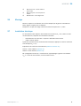
3 Operating and status indicators...................................................... 4
4 Mounting............................................................................................. 5
5 Electrical installation........................................................................ 5
6 Commissioning.................................................................................. 7
7 Troubleshooting................................................................................. 10
7.1 ................................................................................................................... 10
8 Disassembly and disposal............................................................... 11
9 Maintenance...................................................................................... 11
10 Approvals............................................................................................ 12
10.1 Bluetooth® approvals............................................................................... 12
11 Technical data.................................................................................... 12
11.1 Technical data........................................................................................... 12
11.2 Bluetooth technical data®....................................................................... 13
CONTENTS
8022690.10DR | SICK
Subject to change without notice
3

1 Safety information
1.1 General safety notes
■
Read the operating instructions before commissioning.
■
Connection, mounting, and configuration may only be performed by trained
specialists.
■
2006/42/EC
NO
SAFETY
Not a safety component in accordance with the EU Machinery Directive.
■
When commissioning, protect the device from moisture and contamination.
■
These operating instructions contain information required during the life cycle of
the sensor.
1.2 Notes on UL approval
The device must be supplied by a Class 2 source of supply.
UL Environmental Rating: Enclosure type 1
2 Intended use
The WLA16 Bluetooth is an opto-electronic photoelectric retro-reflective sensor
(referred to as “sensor” in the following) for the optical, non-contact detection of
objects, animals, and persons. A reflector is required for this product to function. If the
product is used for any other purpose or modified in any way, any warranty claim
against SICK AG shall become void.
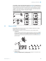
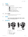
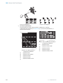
3 Operating and status indicators
20
Ø 12,9
Ø 4,1
39,9
55,4
45,5
5
42
29,9
6
3
6,5
15
27,8
7,7
7,8
7,2
35,5
4,1
8,3
55,7
3
2
34,5
1
4
65
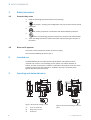
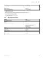
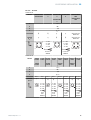
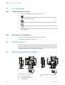
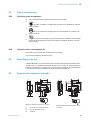
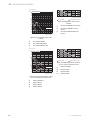
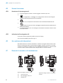
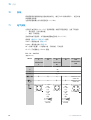
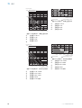
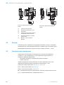
Figure 1: Dimensional drawing 1, cable
1
Center of optical axis
2
Fixing hole, Ø 4.1 mm
3
Connection
20
M12
18
Ø 4,1
39,9
55,4
55,7
45,5 5
7
42
29,9
52,9
6
17,5
3
6,5
15
28
7,5
35,5
4,1
3
2
34,5
1
4
65
Figure 2: Dimensional drawing 2, male con‐
nector
1 SAFETY INFORMATION
4
8022690.10DR | SICK
Subject to change without notice

4
LED indicator green: Supply voltage
active
5
LED indicator yellow: Status of
received light beam
6
BluePilot blue: Alignment aid
4 Mounting
Mount the sensor and the reflector using suitable mounting brackets (see the SICK
range of accessories). Align the sensor and reflector with each other.
Note the sensor's maximum permissible tightening torque of < 1,3 Nm.
5 Electrical installation
The sensors must be connected in a voltage-free state (U
V
= 0 V). The following informa‐
tion must be observed, depending on the connection type:
– Male connector connection: Note pin assignment
– Cable: wire color
Only apply voltage/switch on the voltage supply (U
V
> 0 V) once all electrical connec‐
tions have been established.
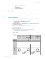
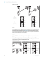
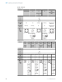
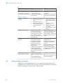
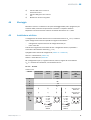
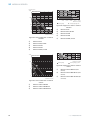
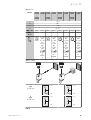
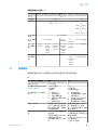
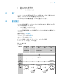
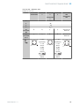
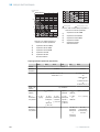
Explanations of the connection diagram (table 1- table 2)
Alarm = alarm output (table 4)
Health = alarm output (table 4)
MF (pin 2 configuration) = external input, teach-in, switching signal
Q
L1
/C = switching output, IO-Link communication
DC: 10 ... 30 V DC
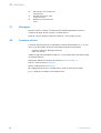
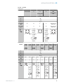
Table 1: DC
WLA16 -24162xxxA00
-34162xxxA00
-1x162xxxA0
0
-24161xxxA0
0
-34161xxxA0
0
-1x161xxxA0
0
-2416xxxxA01-
A99
-3416xxxxA01-
A99
1 + (L+)
2 MF
3 - (M)
4 Q
L1
/C
Default: MF
Q Q
Q Q www.sick.com
8022709
Default:
Q
L1
/C
Q Q
Q Q
www.sick.com
8022709
1
2
4 3
1 = brn
2 = wht
3 = blu
4 = blk
0.14 mm
2
AWG26
1
2
4 3
1 = brn
2 = wht
3 = blu
4 = blk
0.14 mm
2
AWG26
1
2
4 3
MOUNTING 4
8022690.10DR | SICK
Subject to change without notice
5

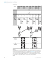
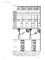
Table 2: DC
WLA16 -24165
xxxA00
-34165
xxxA00
-1x165
xxxA00
-24163
xxxA00
-34163
xxxA00
-1x163x
xxA00
-24166x
xxA00
-34166x
xxA00
-1x166x
xxA00
-24164x
xxA00
-34164x
xxA00
-1x164x
xxA00
1 + (L+)
2 MF
3 - (M)
4 Q
L1
/C
Default: MF Alarm Alarm Alarm Alarm Health Health Health Health
Default:
Q
L1
/C
Q Q
Q Q
Q Q
Q Q
1
2
4 3
1 = brn
2 = wht
3 = blu
4 = blk
0.14 m
m
2
AWG26
1
2
4 3
1 = brn
2 = wht
3 = blu
4 = blk
0.14 m
m
2
AWG26
1
2
4 3
1 = brn
2 = wht
3 = blu
4 = blk
0.14 m
m
2
AWG26
1
2
4 3
1 = brn
2 = wht
3 = blu
4 = blk
0.14 m
m
2
AWG26
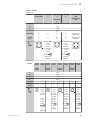
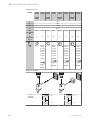
Table 3: Push/pull
Q
Push-pull
(≤ 100 mA)
+ (L+)
Q
‒ (M)
+ (L+)
Q
‒ (M)
Q
Push-pull
(≤ 100 mA)
+ (L+)
Q
‒ (M)
+ (L+)
Q
‒ (M)
Alarm
Alarm output: The sensor (WLA16 Bluetooth) features a pre-failure notification output
(“Alarm” in connection diagram table 4), which issues a notification if the sensor is only
ready for operation to a limited extent. The LED indicator flashes in this case. Possible
causes: Sensor or reflector is contaminated, sensor is out of alignment. In the good
state: LOW (0), if excessively contaminated HIGH (1).
5
ELECTRICAL INSTALLATION
6
8022690.10DR | SICK
Subject to change without notice

Health
Health output: The sensor (WLA16 Bluetooth) features a pre-failure notification output
(“Health” in connection diagram table 4), which issues a notification if the sensor is
only ready for operation to a limited extent or the cable has been interrupted. Possible
causes: Sensor or reflector is contaminated, sensor is out of alignment, cable is dam‐
aged. In the good state: HIGH (1), if excessively contaminated or in the event of cable
interruption LOW (0). The yellow LED indicator flashes in this case.
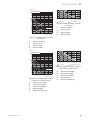
Table 4: Alarm / Health
Alarm (≤ 100 mA) Health (≤100 mA)
+ (L+)
Alarm
‒ (M)
+ (L+)
Health
‒ (M)
+ (L+)
Alarm
‒ (M)
+ (L+)
Health
‒ (M)
6 Commissioning
Bluetooth® is switched on for initial commissioning. You can get SOPASair in the Google
PlayStore (Android) and in the App Store (iOS).
Operating system requirements: Android version 6.0, most current version of iOS.
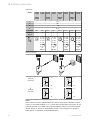
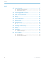
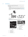
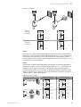
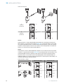
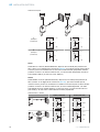
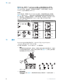
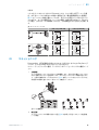
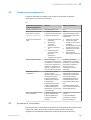
1 Alignment
Align the sensor with a suitable reflector. Select the position so that the red emitted light
beam hits the center of the reflector. The sensor must have a clear view of the reflector,
with no object in the path of the beam [see figure 3]. You must ensure that the optical
openings of the sensor and reflector are completely clear.
Figure 3: Alignment 1 Figure 4: Alignment 2
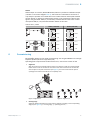
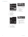
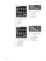
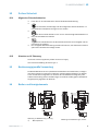
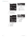
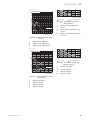
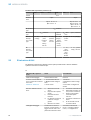
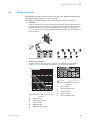
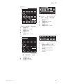
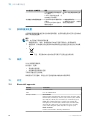
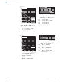
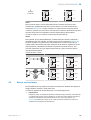
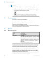
2 Sensing range
Adjust the distance between the sensor and the reflector according to the corresponding
diagram [see figure 5] (x = sensing range, y = operating reserve).
COMMISSIONING 6
8022690.10DR | SICK
Subject to change without notice
7

0
1,000
100
10
1
2
(6.56)
4
(13.12)
10
(32.81)
8
(26.25)
6
(19.69)
Function reserve
Distance in m (feet)
4
2
1
3
5
Sensing range
WLA16P-xxxxx1xx
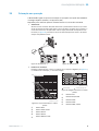
Figure 5: Characteristic line 1: Standard
reflector
1
Reflector PL22
2
Reflector P250, PL30A
3
Reflector PL20A
4
Reflector PL40A
5
Reflector PL80A, C110A
Sensing range Sensing range typ. max.
1
2
3
4
5
0
3.5 50
6 80
3 4
0
6.5 9
0
7 10
0
8
(26.25)
Distance in m (feet)
2
(6.56)
6
(19.69)
10
(32.81)
4
(13.12)
Figure 6: Bar graph 1: Standard reflector
1
Reflector PL22
2
Reflector P250, PL30A
3
Reflector PL20A
4
Reflector PL40A
5
Reflector PL80A, C110A
0
100
10
1
3
2
1
1,000
2
(6.56)
4
(13.12)
10
(32.81)
8
(26.25)
6
(19.69)
Function reserve
Distance in m (feet)
Sensing range
WLA16P-xxxxx1xx
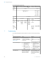
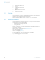
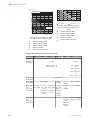
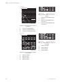
Figure 7: Characteristic line 2: Reflective
tape
1
Reflective tape REF-DG
2
Reflective tape REF-IRF-56
3
Reflective tape REF-AC1000
1
2
3
0
0
1 2
0
1.8 3
0
4.5 6
0
Sensing range Sensing range typ. max.
8
(26.25)
Distance in m (feet)
2
(6.56)
6
(19.69)
10
(32.81)
4
(13.12)
Figure 8: Bar graph 2: Reflective tape
1
Reflective tape REF-DG (50 x
50 mm)
2
Reflective tape REF-IRF-56 (50 x
50 mm)
3
Reflective tape REF-AC1000 (50 x
50 mm)
6 COMMISSIONING
8
8022690.10DR | SICK
Subject to change without notice

1,000
100
10
1
4
3
1
2
0
2
(6.56)
4
(13.12)
10
(32.81)
8
(26.25)
6
(19.69)
Function reserve
Distance in m (feet)
Sensing range
WLA16P-xxxxx1xx
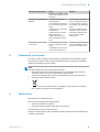
Figure 9: Characteristic line 3: Fine triple
reflectors
1
Reflector PL10FH-1
2
Reflector PL10F
3
Reflector PL20F
4
Reflector P250F
1
2
3
4
0
0
3 4
0
2.5 3
0
3.8 5
0
6 8
0
Sensing range Sensing range typ. max.
8
(26.25)
Distance in m (feet)
2
(6.56)
6
(19.69)
10
(32.81)
4
(13.12)
Figure 10: Bar graph 3: Fine triple reflec‐
tors
1
Reflector PL10FH-1
2
Reflector PL10F
3
Reflector PL20F
4
Reflector P250F
0
1,000
100
10
1
2
(6.56)
4
(13.12)
10
(32.81)
8
(26.25)
6
(19.69)
Function reserve
Distance in m (feet)
5
4
3
21
Sensing range
WLA16P-xxxxx1xx
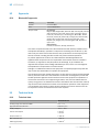
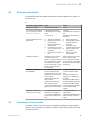
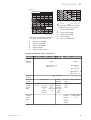
Figure 11: Characteristic line 4: Chemical-
resistant reflector
1
Reflector PL10F CHEM
2
Reflector PL20 CHEM
3
Reflector P250 CHEM
4
Reflector P250H
5
Reflector PL40A Antifog
Sensing range Sensing range typ. max.
1
2
3
4
5
0
0 8
(26.25)
1.4 2
0
2.4 3.5
0
3.5 5
0
4 6
0
6 8
0
Distance in m (feet)
2
(6.56)
6
(19.69)
10
(32.81)
4
(13.12)
Figure 12: Bar graph 4: Chemical-resistant
reflector
1
Reflector PL10F CHEM
2
Reflector PL20 CHEM
3
Reflector P250 CHEM
4
Reflector P250H
5
Reflector PL40A Antifog
COMMISSIONING 6
8022690.10DR | SICK
Subject to change without notice
9

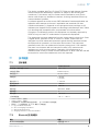
Process data structure (Version 1.1)
A00 A70 A71 A72 A73 A75
IO-Link V1.1
Process
data
2 bytes 4 bytes
Byte 0: bits 15... 8
Byte 1: bits 7... 0
Byte 0: bits 31...
24
Byte 1: bits 13...
16
Byte 2: bits 15...
8
Byte 3: bits 7... 0
Bit 0 / Data
type
Q
L1
/ Boolean
Bit 1 / Data
type
Q
L2
/ Boolean Qint.1 /
Boolean
Q
L2
/
Boolean
Qint.1 / Boolean
Bit... /
Descrip‐
tion / Data
type
2 ...15 /
[empty]
2 ...15 /
[time mea‐
surement
value] /
UInt 14
2 … 15 /
[counter
value] /
UInt 14
2 … 15 /
[length /
speed
measure‐
ment] /
SInt14
2 / Qint.
1 /
Boolean
2 … 7 / [empty]
Bit... /
Descrip‐
tion / Data
type
3 … 15 /
[time mea‐
surement
value] /
UInt13
8 … 31 / [carrier
load] / UInt 24
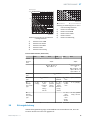
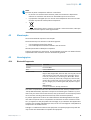
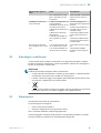
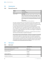
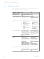
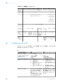
7 Troubleshooting
The Troubleshooting table indicates measures to be taken if the sensor stops working.
en
LED indicator/fault pattern Cause Measures
Green LED flashes IO-Link communication None
Switching outputs do not
behave in accordance with
table 3 - table 4
1. IO-Link communication
2. Change of the configuration
3. Short-circuit
1. None
2. Adjustment of the configura‐
tion
3. Check electrical connections
Not all blue LEDs light up. a) Insufficient alignment
b) Contamination of the
optical surfaces
c) Particles in the light
beam
d) Distance between sen‐
sor and reflector is too
large
e) Reflector is not suitable
a) Check alignment
b) Cleaning of the optical
surfaces (sensor and
reflector).
c) Avoid contamination in
the air as far as possible
d) Check sensing range
e) SICK reflector is recom‐
mended
Yellow LED flashes Distance between sensor and
reflector is too large / light
beam is not completely
aligned to the reflector /
Check sensing range / check
alignment / SICK reflector is
recommended / Cleaning of
the optical surfaces (sensor
and reflector).
6 COMMISSIONING
10
8022690.10DR | SICK
Subject to change without notice

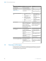
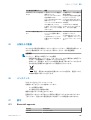
LED indicator/fault pattern Cause Measures
reflector is not suitable / Front
screen and/or reflector is con‐
taminated.
The sensor is not displayed in
SOPASair
1. Connection to another
hand-held exists.
2.The hand-held is outside of
the transmission range of the
sensor.
3. Bluetooth LE in the sensor
is deactivated.
4. Bluetooth LE in the hand-
held is deactivated.
5. MAC address filter acti‐
vated, hand-held not autho‐
rized.
1. No connection or deactiva‐
tion of the existing connection.
2. Thorough check of installa‐
tion situation (e.g. shielding by
metal).
3. Activation of Bluetooth LE
via SiLink2 master or IO-Link
4. Activation of Bluetooth LE
5. No or change to MAC
address filter.
No connection can be made
to the sensor
1. The Android or iOS version
does not comply with require‐
ments.
2. SOPASair version does not
contain the required driver.
1. Check the operating system.
2. Uninstall SOPASair, install
the most current app version.
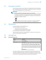
8 Disassembly and disposal
The sensor must be disposed of according to the applicable country-specific regula‐
tions. Efforts should be made during the disposal process to recycle the constituent
materials (particularly precious metals).
NOTE
Disposal of batteries, electric and electronic devices
•
According to international directives, batteries, accumulators and electrical or
electronic devices must not be disposed of in general waste.
•
The owner is obliged by law to return this devices at the end of their life to the
respective public collection points.
•
This symbol on the product, its package or in this document, indicates
that a product is subject to these regulations.
9 Maintenance
SICK sensors are maintenance-free.
We recommend doing the following regularly:
•
Clean the external lens surfaces
•
Check the screw connections and plug-in connections
No modifications may be made to devices.
Subject to change without notice. Specified product properties and technical data are
not written guarantees.
DISASSEMBLY AND DISPOSAL 8
8022690.10DR | SICK
Subject to change without notice
11

10 Approvals
10.1 Bluetooth® approvals
Country Comments
Canada IC: 21147-W16
USA FCC ID: 2AHDR-W16
Europe + EFTA EU countries
Belgium (BE), Bulgaria (BG), Denmark (DK), Germany (DE), Estonia
(EE), Finland (FI), France (FR), Greece (GR), Ireland (IE), Italy (IT),
Latvia (LV), Lithuania (LT), Luxembourg (LU), Malta (MT), Nether‐
lands (NL), Austria (AT), Poland (PL), Portugal (PT), Romania (RO),
Sweden (SE), Slovakia (SK), Slovenia (SI), Spain (ES), Czech
Republic (CZ), Hungary (HU), United Kingdom (GB), Republic of
Cyprus (CY).
EFTA countries
Iceland, Liechtenstein, Norway, Switzerland
This device complies with Part 15 of the FCC Rules and with Industry Canada licence-
exempt RSS standard(s). Operation is subject to the following two conditions: (1) this
device may not cause harmful interference, and (2) this device must accept any inter‐
ference received, including interference that may cause undesired operation.
Le présent appareil est conforme aux CNR d'Industrie Canada applicables aux
appareils radio exempts de licence. L'exploitation est autorisée aux deux conditions
suivantes: (1) l'appareil ne doit pas produire de brouillage, et (2) l'utilisateur de
l'appareil doit accepter tout brouillage radioélectrique subi, même si le brouillage est
susceptible d'en compromettre le fonctionnement.
Changes or modifications made to this equipment not expressly approved by SICK AG
may void the FCC authorization to operate this equipment.
This equipment has been tested and found to comply with the limits for a Class A digital
device, pursuant to Part 15 of the FCC Rules. These limits are designed to provide rea‐
sonable protection against harmful interference when the equipment is operated in a
commercial environment. This equipment generates, uses, and can radiate radio fre‐
quency energy and, if not installed and used in accordance with the instruction manual,
may cause harmful interference to radio communications. Operation of this equipment
in a residential area is likely to cause harmful interference in which case the user will
be required to correct the interference at his own expense.
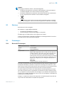
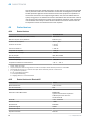
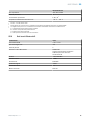
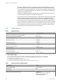
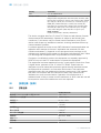
11 Technical data
11.1 Technical data
WLA16 Bluetooth
Sensing range (with reflector PL80A) 0 m ... 7 m
Light spot diameter/distance Ø 80 mm (5 m)
Supply voltage V
S
DC 10 ... 30 V
Current consumption ≤ 30 mA
1
< 50 mA
2
Output current I
max.
≤ 100 mA
Max. response time ≤ 500 μs
3
Switching frequency 1,000 Hz
4
10 APPROVALS
12
8022690.10DR | SICK
Subject to change without notice

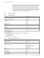
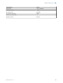
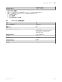
WLA16 Bluetooth
Enclosure rating IP66, IP67, IP69K
Protection class III
Circuit protection A, B, C, D
5
Ambient operating temperature –40 °C ... +60 °C
1
16 VDC to 30 VDC, without load
2
10 VDC to 16 VDC, without load
3
Signal transit time with resistive load in switching mode. Deviating values possible in COM2 mode.
4
With a light/dark ratio of 1:1 in switching mode. Deviating values possible in IO-Link mode.
5
A = U
V
-connections reverse polarity protected
B = inputs and output reverse-polarity protected
C = Interference suppression
D = outputs overcurrent and short-circuit protected
11.2 Bluetooth technical data®
Features Values
Bluetooth® sensing range 100 m on sight
Radio type BLE
Radio class 2
Bluetooth® module manufacturer BROADCOM
Cypress Semiconductor Corporation
198 Champion Court San Jose
CA 95134-1709
RF band 2,402 - 2,480 MHz
Output power 2 dBM
Declaration ID D033906
Qualified design ID 89630
Specification name 4.1
Member company SICK AG
TECHNICAL DATA 11
8022690.10DR | SICK
Subject to change without notice
13


Beschriebenes Produkt
WLA16 - Bluetooth®
Hersteller
SICK AG
Erwin-Sick-Str. 1
79183 Waldkirch
Deutschland
Rechtliche Hinweise
Dieses Werk ist urheberrechtlich geschützt. Die dadurch begründeten Rechte bleiben
bei der Firma SICK AG. Die Vervielfältigung des Werks oder von Teilen dieses Werks ist
nur in den Grenzen der gesetzlichen Bestimmungen des Urheberrechtsgesetzes zuläs‐
sig. Jede Änderung, Kürzung oder Übersetzung des Werks ohne ausdrückliche schriftli‐
che Zustimmung der Firma SICK AG ist untersagt.
Die in diesem Dokument genannten Marken sind Eigentum ihrer jeweiligen Inhaber.
© SICK AG. Alle Rechte vorbehalten.
Originaldokument
Dieses Dokument ist ein Originaldokument der SICK AG.
8022690.10DR | SICK
Subject to change without notice
15

Inhalt
12 Zu Ihrer Sicherheit............................................................................. 17
12.1 Allgemeine Sicherheitshinweise.............................................................. 17
12.2 Hinweise zur UL Zulassung...................................................................... 17
13 Bestimmungsgemäße Verwendung............................................... 17
14 Bedien- und Anzeigeelemente........................................................ 17
15 Montage.............................................................................................. 18
16 Elektrische Installation..................................................................... 18
17 Inbetriebnahme................................................................................. 21
18 Störungsbehebung............................................................................ 23
18.1 ................................................................................................................... 24
19 Demontage und Entsorgung............................................................ 24
20 Wartung.............................................................................................. 25
21 Zulassungen....................................................................................... 25
21.1 Bluetooth® Zulassungen......................................................................... 25
22 Technische Daten.............................................................................. 26
22.1 Technische Daten..................................................................................... 26
22.2 Technische Daten Bluetooth®................................................................. 26
INHALT
16
8022690.10DR | SICK
Subject to change without notice

12 Zu Ihrer Sicherheit
12.1 Allgemeine Sicherheitshinweise
■
Lesen Sie vor der Inbetriebnahme des Geräts die Betriebsanleitung.
■
Der Anschluss, die Montage und die Konfiguration des Geräts dürfen nur
von geschultem Fachpersonal vorgenommen werden.
■
2006/42/EC
NO
SAFETY
Bei diesem Gerät handelt es sich um kein sicherheitsgerichtetes Bauteil im
Sinne der EU-Maschinenrichtlinie.
■
Bei der Inbetriebnahme ist das Gerät ausreichend vor Feuchtigkeit und Ver‐
schmutzung zu schützen.
■
Die vorliegende Betriebsanleitung enthält Informationen, die während des Lebens‐
zyklus der Lichtschranke benötigt werden.
12.2 Hinweise zur UL Zulassung
The device must be supplied by a Class 2 source of supply.
UL Environmental Rating: Enclosure type 1
13 Bestimmungsgemäße Verwendung
Die WLA16 Bluetooth ist eine optoelektronische Reflexions-Lichtschranke (im Folgen‐
den Sensor genannt) und wird zum optischen, berührungslosen Erfassen von Sachen,
Tieren und Personen eingesetzt. Zur Funktion wird ein Reflektor benötigt. Bei jeder
anderen Verwendung und bei Veränderungen am Produkt verfällt jeglicher Gewährleis‐
tungsanspruch gegenüber der SICK AG.
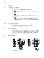
14 Bedien- und Anzeigeelemente
20
Ø 12,9
Ø 4,1
39,9
55,4
45,5
5
42
29,9
6
3
6,5
15
27,8
7,7
7,8
7,2
35,5
4,1
8,3
55,7
3
2
34,5
1
4
65
Abbildung 13: Maßzeichnung 1, Leitung
1
Mitte Optikachse
20
M12
18
Ø 4,1
39,9
55,4
55,7
45,5 5
7
42
29,9
52,9
6
17,5
3
6,5
15
28
7,5
35,5
4,1
3
2
34,5
1
4
65
Abbildung 14: Maßzeichnung 2, Stecker
ZU IHRER SICHERHEIT 12
8022690.10DR | SICK
Subject to change without notice
17

2
Befestigungsbohrung, Ø 4,1 mm
3
Anschluss
4
Anzeige-LED grün: Betriebsspan‐
nung aktiv
5
Anzeige-LED gelb: Status Lichtemp‐
fang
6
BluePilot blau: Ausrichthilfe
15 Montage
Sensor und Reflektor an geeignete Befestigungswinkel montieren (siehe SICK-Zubehör-
Programm). Sensor und Reflektor zueinander ausrichten.
Maximal zulässiges Anzugsdrehmoment des Sensors von < 1,3 Nm beachten.
16 Elektrische Installation
Anschluss der Sensoren muss spannungsfrei (U
V
= 0 V) erfolgen. Je nach Anschlussart
sind die folgenden Informationen zu beachten:
– Steckeranschluss: Pinbelegung beachten
– Leitung: Adernfarbe
Erst nach Anschluss aller elektrischen Verbindungen die Spannungsversorgung (U
V
> 0
V) anlegen bzw. einschalten.
Erläuterungen zum Anschlussschema (Tabelle 5 - Tabelle 6)
Alarm = Alarmausgang (Tabelle 8)
Health = Alarmausgang (Tabelle 8)
MF (Pin-2-Konfiguration) = Externer Eingang, Teach-in, Schaltsignal
Q
L1
/C = Schaltausgang, IO-Link Kommunikation
15 MONTAGE
18
8022690.10DR | SICK
Subject to change without notice

DC: 10 ... 30 V DC
Tabelle 5: DC
WLA16 -24162xxxA00
-34162xxxA00
-1x162xxxA0
0
-24161xxxA0
0
-34161xxxA0
0
-1x161xxxA0
0
-2416xxxxA01-
A99
-3416xxxxA01-
A99
1 + (L+)
2 MF
3 - (M)
4 Q
L1
/C
Default: MF
Q Q
Q Q www.sick.com
8022709
Default:
Q
L1
/C
Q Q
Q Q
www.sick.com
8022709
1
2
4 3
1 = brn
2 = wht
3 = blu
4 = blk
0.14 mm
2
AWG26
1
2
4 3
1 = brn
2 = wht
3 = blu
4 = blk
0.14 mm
2
AWG26
1
2
4 3
Tabelle 6: DC
WLA16 -24165
xxxA00
-34165
xxxA00
-1x165
xxxA00
-24163
xxxA00
-34163
xxxA00
-1x163x
xxA00
-24166x
xxA00
-34166x
xxA00
-1x166x
xxA00
-24164x
xxA00
-34164x
xxA00
-1x164x
xxA00
1 + (L+)
2 MF
3 - (M)
4 Q
L1
/C
Default: MF Alarm Alarm Alarm Alarm Health Health Health Health
Default:
Q
L1
/C
Q Q
Q Q
Q Q
Q Q
1
2
4 3
1 = brn
2 = wht
3 = blu
4 = blk
0.14
mm
2
AWG26
1
2
4 3
1 = brn
2 = wht
3 = blu
4 = blk
0.14
mm
2
AWG26
1
2
4 3
1 = brn
2 = wht
3 = blu
4 = blk
0.14
mm
2
AWG26
1
2
4 3
1 = brn
2 = wht
3 = blu
4 = blk
0.14
mm
2
AWG26
ELEKTRISCHE INSTALLATION 16
8022690.10DR | SICK
Subject to change without notice
19
La pagina sta caricando ...
La pagina sta caricando ...
La pagina sta caricando ...
La pagina sta caricando ...
La pagina sta caricando ...
La pagina sta caricando ...
La pagina sta caricando ...
La pagina sta caricando ...
La pagina sta caricando ...
La pagina sta caricando ...
La pagina sta caricando ...
La pagina sta caricando ...
La pagina sta caricando ...
La pagina sta caricando ...
La pagina sta caricando ...
La pagina sta caricando ...
La pagina sta caricando ...
La pagina sta caricando ...
La pagina sta caricando ...
La pagina sta caricando ...
La pagina sta caricando ...
La pagina sta caricando ...
La pagina sta caricando ...
La pagina sta caricando ...
La pagina sta caricando ...
La pagina sta caricando ...
La pagina sta caricando ...
La pagina sta caricando ...
La pagina sta caricando ...
La pagina sta caricando ...
La pagina sta caricando ...
La pagina sta caricando ...
La pagina sta caricando ...
La pagina sta caricando ...
La pagina sta caricando ...
La pagina sta caricando ...
La pagina sta caricando ...
La pagina sta caricando ...
La pagina sta caricando ...
La pagina sta caricando ...
La pagina sta caricando ...
La pagina sta caricando ...
La pagina sta caricando ...
La pagina sta caricando ...
La pagina sta caricando ...
La pagina sta caricando ...
La pagina sta caricando ...
La pagina sta caricando ...
La pagina sta caricando ...
La pagina sta caricando ...
La pagina sta caricando ...
La pagina sta caricando ...
La pagina sta caricando ...
La pagina sta caricando ...
La pagina sta caricando ...
La pagina sta caricando ...
La pagina sta caricando ...
La pagina sta caricando ...
La pagina sta caricando ...
La pagina sta caricando ...
La pagina sta caricando ...
La pagina sta caricando ...
La pagina sta caricando ...
La pagina sta caricando ...
La pagina sta caricando ...
La pagina sta caricando ...
La pagina sta caricando ...
La pagina sta caricando ...
La pagina sta caricando ...
La pagina sta caricando ...
La pagina sta caricando ...
La pagina sta caricando ...
La pagina sta caricando ...
La pagina sta caricando ...
La pagina sta caricando ...
La pagina sta caricando ...
La pagina sta caricando ...
La pagina sta caricando ...
La pagina sta caricando ...
La pagina sta caricando ...
La pagina sta caricando ...
La pagina sta caricando ...
La pagina sta caricando ...
La pagina sta caricando ...
La pagina sta caricando ...
La pagina sta caricando ...
La pagina sta caricando ...
La pagina sta caricando ...
La pagina sta caricando ...
La pagina sta caricando ...
La pagina sta caricando ...
La pagina sta caricando ...
La pagina sta caricando ...
La pagina sta caricando ...
La pagina sta caricando ...
La pagina sta caricando ...
La pagina sta caricando ...
La pagina sta caricando ...
La pagina sta caricando ...
La pagina sta caricando ...
La pagina sta caricando ...
-
 1
1
-
 2
2
-
 3
3
-
 4
4
-
 5
5
-
 6
6
-
 7
7
-
 8
8
-
 9
9
-
 10
10
-
 11
11
-
 12
12
-
 13
13
-
 14
14
-
 15
15
-
 16
16
-
 17
17
-
 18
18
-
 19
19
-
 20
20
-
 21
21
-
 22
22
-
 23
23
-
 24
24
-
 25
25
-
 26
26
-
 27
27
-
 28
28
-
 29
29
-
 30
30
-
 31
31
-
 32
32
-
 33
33
-
 34
34
-
 35
35
-
 36
36
-
 37
37
-
 38
38
-
 39
39
-
 40
40
-
 41
41
-
 42
42
-
 43
43
-
 44
44
-
 45
45
-
 46
46
-
 47
47
-
 48
48
-
 49
49
-
 50
50
-
 51
51
-
 52
52
-
 53
53
-
 54
54
-
 55
55
-
 56
56
-
 57
57
-
 58
58
-
 59
59
-
 60
60
-
 61
61
-
 62
62
-
 63
63
-
 64
64
-
 65
65
-
 66
66
-
 67
67
-
 68
68
-
 69
69
-
 70
70
-
 71
71
-
 72
72
-
 73
73
-
 74
74
-
 75
75
-
 76
76
-
 77
77
-
 78
78
-
 79
79
-
 80
80
-
 81
81
-
 82
82
-
 83
83
-
 84
84
-
 85
85
-
 86
86
-
 87
87
-
 88
88
-
 89
89
-
 90
90
-
 91
91
-
 92
92
-
 93
93
-
 94
94
-
 95
95
-
 96
96
-
 97
97
-
 98
98
-
 99
99
-
 100
100
-
 101
101
-
 102
102
-
 103
103
-
 104
104
-
 105
105
-
 106
106
-
 107
107
-
 108
108
-
 109
109
-
 110
110
-
 111
111
-
 112
112
-
 113
113
-
 114
114
-
 115
115
-
 116
116
-
 117
117
-
 118
118
-
 119
119
-
 120
120
-
 121
121


SICK WLA16 Istruzioni per l'uso
- Tipo
- Istruzioni per l'uso
- Questo manuale è adatto anche per
in altre lingue
- français: SICK WLA16 Mode d'emploi
- 日本語: SICK WLA16 取扱説明書
Documenti correlati
-
SICK WLA16 Istruzioni per l'uso
-
-
-
-
-
-
-
-
-