
Action

AVVERTENZE PER L’INSTALLATORE
OBBLIGHI GENERALI PER LA SICUREZZA
1) ATTENZIONE! È importante per la sicurezza delle persone seguire attentamente tutta l’istruzione.
Una errata installazione o un errato uso del prodotto può portare a gravi danni alle persone.
2) Leggere attentamente le istruzioni prima di iniziare l’installazione del prodotto.
3) I materiali dell’imballaggio (plastica, polistirolo, ecc.) non devono essere lasciati alla portata
dei bambini in quanto potenziali fonti di pericolo.
4) Conservare le istruzioni per riferimenti futuri.
5) Questo prodotto è stato progettato e costruito esclusivamente per l’utilizzo indicato in questa
documentazione. Qualsiasi altro utilizzo non espressamente indicato potrebbe pregiudicare
l’integrità del prodotto e/o rappresentare fonte di pericolo.
6) GENIUS declina qualsiasi responsabilità derivata dall’uso improprio o diverso da quello per cui
l’automatismo è destinato.
7) Non installare l’apparecchio in atmosfera esplosiva: la presenza di gas o fumi infiammabili
costituisce un grave pericolo per la sicurezza.
8) Gli elementi costruttivi meccanici devono essere in accordo con quanto stabilito dalle Norme
EN 12604 e EN 12605.
Per i Paesi extra-CEE, oltre ai riferimenti normativi nazionali, per ottenere un livello di sicurezza
adeguato, devono essere seguite le Norme sopra riportate.
9) GENIUS non è responsabile dell’inosservanza della Buona Tecnica nella costruzione delle
chiusure da motorizzare, nonché delle deformazioni che dovessero intervenire nell’utilizzo.
10) L’installazione deve essere effettuata nell’osservanza delle Norme EN 12453 e EN 12445. Il livello
di sicurezza dell’automazione deve essere C+D.
11) Prima di effettuare qualsiasi intervento sull’impianto, togliere l’alimentazione elettrica e scollegare
le batterie.
12) Prevedere sulla rete di alimentazione dell’automazione un interruttore onnipolare con distanza
d’apertura dei contatti uguale o superiore a 3 mm. È consigliabile l’uso di un magnetotermico
da 6A con interruzione onnipolare.
13) Verificare che a monte dell’impianto vi sia un interruttore differenziale con soglia da 0,03 A.
14) Verificare che l’impianto di terra sia realizzato a regola d’arte e collegarvi le parti metalliche
della chiusura.
15) L’automazione dispone di una sicurezza intrinseca antischiacciamento costituita da un control-
lo di coppia. E' comunque necessario verificarne la sogli di intervento secondo quanto
previsto dalle Norme indicate al punto 10.
16) I dispositivi di sicurezza (norma EN 12978) permettono di proteggere eventuali aree di pericolo
da Rischi meccanici di movimento, come ad Es. schiacciamento, convogliamento,
cesoiamento.
17) Per ogni impianto è consigliato l’utilizzo di almeno una segnalazione luminosa nonché di un
cartello di segnalazione fissato adeguatamente sulla struttura dell’infisso, oltre ai dispositivi citati
al punto “16”.
18) GENIUS declina ogni responsabilità ai fini della sicurezza e del buon funzionamento dell’auto-
mazione, in caso vengano utilizzati componenti dell’impianto non di produzione GENIUS.
19) Per la manutenzione utilizzare esclusivamente parti originali GENIUS.
20) Non eseguire alcuna modifica sui componenti facenti parte del sistema d’automazione.
21) L’installatore deve fornire tutte le informazioni relative al funzionamento manuale del sistema in
caso di emergenza e consegnare all’Utente utilizzatore dell’impianto il libretto d’avvertenze
allegato al prodotto.
22) Non permettere ai bambini o persone di sostare nelle vicinanze del prodotto durante il
funzionamento.
23) Tenere fuori dalla portata dei bambini radiocomandi o qualsiasi altro datore di impulso, per
evitare che l’automazione possa essere azionata involontariamente.
24) Il transito tra le ante deve avvenire solo a cancello completamente aperto.
25) L’Utente utilizzatore deve astenersi da qualsiasi tentativo di riparazione o d’intervento diretto e
rivolgersi solo a personale qualificato.
26) Non mettere in corto circuito i poli delle batterie e non tentare di ricaricarle con alimentatori
diversi dalle schede Master o Slave.
27) Non gettare le batterie esauste nei rifiuti ma smaltirle utilizzando gli appositi contenitori per
consentirne il riciclaggio. I costi di smaltimento sono già stati pagati dalla casa costruttrice.
28) Tutto quello che non è previsto espressamente in queste istruzioni non è permesso
IMPORTANT NOTICE FOR THE INSTALLER
GENERAL SAFETY REGULATIONS
1) ATTENTION! To ensure the safety of people, it is important that you read all the following
instructions. Incorrect installation or incorrect use of the product could cause serious harm to
people.
2) Carefully read the instructions before beginning to install the product.
3) Do not leave packing materials (plastic, polystyrene, etc.) within reach of children as such
materials are potential sources of danger.
4) Store these instructions for future reference.
5) This product was designed and built strictly for the use indicated in this documentation. Any other
use, not expressly indicated here, could compromise the good condition/operation of the
product and/or be a source of danger.
6) GENIUS declines all liability caused by improper use or use other than that for which the
automated system was intended.
7) Do not install the equipment in an explosive atmosphere: the presence of inflammable gas or
fumes is a serious danger to safety.
8) The mechanical parts must conform to the provisions of Standards EN 12604 and EN 12605.
For non-EU countries, to obtain an adequate level of safety, the Standards mentioned above
must be observed, in addition to national legal regulations.
9) GENIUS is not responsible for failure to observe Good Technique in the construction of the
closing elements to be motorised, or for any deformation that may occur during use.
10) The installation must conform to Standards EN 12453 and EN 12445. The safety level of the
automated system must be C+D.
11) Before attempting any job on the system, cut out electrical power and disconnect the
batteries.
12) The mains power supply of the automated system must be fitted with an all-pole switch with
contact opening distance of 3mm or greater. Use of a 6A thermal breaker with all-pole circuit
break is recommended.
13) Make sure that a differential switch with threshold of 0.03 A is fitted upstream of the system.
CONSIGNES POUR L'INSTALLATEUR
RÈGLES DE SÉCURITÉ
1) ATTENTION! Il est important, pour la sécurité des personnes, de suivre à la lettre toutes les
instructions. Une installation erronée ou un usage erroné du produit peut entraîner de graves
conséquences pour les personnes.
2) Lire attentivement les instructions avant d'installer le produit.
3) Les matériaux d'emballage (matière plastique, polystyrène, etc.) ne doivent pas être laissés
à la portée des enfants car ils constituent des sources potentielles de danger.
4) Conserver les instructions pour les références futures.
5) Ce produit a été conçu et construit exclusivement pour l'usage indiqué dans cette
documentation. Toute autre utilisation non expressément indiquée pourrait compromettre
l'intégrité du produit et/ou représenter une source de danger.
6) GENIUS décline toute responsabilité qui dériverait d'usage impropre ou différent de celui
auquel l'automatisme est destiné.
7) Ne pas installer l'appareil dans une atmosphère explosive: la présence de gaz ou de fumées
inflammables constitue un grave danger pour la sécurité.
8) Les composants mécaniques doivent répondre aux prescriptions des Normes EN 12604 et EN
12605.
Pour les Pays extra-CEE, l'obtention d'un niveau de sécurité approprié exige non seulement le
respect des normes nationales, mais également le respect des Normes susmentionnées.
9) GENIUS n'est pas responsable du non-respect de la Bonne Technique dans la construction des
fermetures à motoriser, ni des déformations qui pourraient intervenir lors de l'utilisation.
10) L'installation doit être effectuée conformément aux Normes EN 12453 et EN 12445. Le niveau de
sécurité de l'automatisme doit être C+D.
11) Couper l'alimentation électrique et déconnecter la batterie avant toute intervention sur
l'installation.
12) Prévoir, sur le secteur d'alimentation de l'automatisme, un interrupteur omnipolaire avec une
distance d'ouverture des contacts égale ou supérieure à 3 mm. On recommande d'utiliser un
magnétothermique de 6A avec interruption omnipolaire.
13) Vérifier qu'il y ait, en amont de l'installation, un interrupteur différentiel avec un seuil de 0,03 A.
14) Vérifier que la mise à terre est réalisée selon les règles de l'art et y connecter les pièces
métalliques de la fermeture.
15) L'automatisme dispose d'une sécurité intrinsèque anti-écrasement, formée d'un contrôle du
couple. Il est toutefois nécessaire d'en vérifier le seuil d'intervention suivant les prescriptions des
Normes indiquées au point 10.
16) Les dispositifs de sécurité (norme EN 12978) permettent de protéger des zones éventuellement
dangereuses contre les Risques mécaniques du mouvement, comme l'écrasement,
l'acheminement, le cisaillement.
17) On recommande que toute installation soit doté au moins d'une signalisation lumineuse, d'un
panneau de signalisation fixé, de manière appropriée, sur la structure de la fermeture, ainsi que
des dispositifs cités au point “16”.
18) GENIUS décline toute responsabilité quant à la sécurité et au bon fonctionnement de
l'automatisme si les composants utilisés dans l'installation n'appartiennent pas à la production
GENIUS.
19) Utiliser exclusivement, pour l'entretien, des pièces GENIUS originales.
20) Ne jamais modifier les composants faisant partie du système d'automatisme.
21) L'installateur doit fournir toutes les informations relatives au fonctionnement manuel du système
en cas d'urgence et remettre à l'Usager qui utilise l'installation les "Instructions pour l'Usager"
fournies avec le produit.
22) Interdire aux enfants ou aux tiers de stationner près du produit durant le fonctionnement.
23) Eloigner de la portée des enfants les radiocommandes ou tout autre générateur d'impulsions,
pour éviter tout actionnement involontaire de l'automatisme.
24) Le transit entre les vantaux ne doit avoir lieu que lorsque le portail est complètement ouvert.
25) L'Usager qui utilise l'installation doit éviter toute tentative de réparation ou d'intervention directe
et s'adresser uniquement à un personnel qualifié.
26) Ne pas mettre en court-circuit les pôles des batteries et ne pas tenter de les recharger avec
d'autres platines d'alimentation que les platines Maître ou Esclave.
27) Ne pas jeter les batteries épuisées à la poubelle, mais les éliminer dans les conteneurs
spécifiques pour le recyclage. Les coûts d'élimination des déchets ont déjà été payés par le
constructeur.
28) Tout ce qui n'est pas prévu expressément dans ces instructions est interdit.
14) Make sure that the earthing system is perfectly constructed, and connect metal parts of the
means of the closure to it.
15) The automated system is supplied with an intrinsic anti-crushing safety device consisting of a
torque control. Nevertheless, its tripping threshold must be checked as specified in the
Standards indicated at point 10.
16) The safety devices (EN 12978 standard) protect any danger areas against mechanical
movement Risks, such as crushing, dragging, and shearing.
17) Use of at least one indicator-light is recommended for every system, as well as a warning sign
adequately secured to the frame structure, in addition to the devices mentioned at point “16”.
18) GENIUS declines all liability as concerns safety and efficient operation of the automated
system, if system components not produced by GENIUS are used.
19) For maintenance, strictly use original parts by GENIUS.
20) Do not in any way modify the components of the automated system.
21) The installer shall supply all information concerning manual operation of the system in case of
an emergency, and shall hand over to the user the warnings handbook supplied with the
product.
22) Do not allow children or adults to stay near the product while it is operating.
23) Keep remote controls or other pulse generators away from children, to prevent the automated
system from being activated involuntarily.
24) Transit through the leaves is allowed only when the gate is fully open.
25) The user must not attempt any kind of repair or direct action whatever and contact qualified
personnel only.
26) Do not short-circuit the poles of the batteries and do not try to recharge the batteries with power
supply units other than Master or Slave cards.
27) Do not throw exhausted batteries into containers for other waste but dispose of them in the
appropriate containers to enable them to be recycled. Disposal costs have already been
paid for by the manufacturer.
28) Anything not expressly specified in these instructions is not permitted.

ADVERTENCIAS PARA EL INSTALADOR
REGLAS GENERALES PARA LA SEGURIDAD
1) ¡ATENCION! Es sumamente importante para la seguridad de las personas seguir atentamente las
presentes instrucciones. Una instalación incorrecta o un uso impropio del producto puede causar
graves daños a las personas.
2) Lean detenidamente las instrucciones antes de instalar el producto.
3) Los materiales del embalaje (plástico, poliestireno, etc.) no deben dejarse al alcance de los
niños, ya que constituyen fuentes potenciales de peligro.
4) Guarden las instrucciones para futuras consultas.
5) Este producto ha sido proyectado y fabricado exclusivamente para la utilización indicada en
el presente manual. Cualquier uso diverso del previsto podría perjudicar el funcionamiento del
producto y/o representar fuente de peligro.
6) GENIUS declina cualquier responsabilidad derivada de un uso impropio o diverso del previsto.
7) No instalen el aparato en atmósfera explosiva: la presencia de gas o humos inflamables
constituye un grave peligro para la seguridad.
8) Los elementos constructivos mecánicos deben estar de acuerdo con lo establecido en las
Normas EN 12604 y EN 12605.
Para los países no pertenecientes a la CEE, además de las referencias normativas nacionales,
para obtener un nivel de seguridad adecuado, deben seguirse las Normas arriba indicadas.
9 ) GENIUS no es responsable del incumplimiento de las buenas técnicas de fabricación de los cierres que
se han de motorizar, así como de las deformaciones que pudieran intervenir en la utilización.
10) La instalación debe ser realizada de conformidad con las Normas EN 12453 y EN 12445. E l
nivel de seguridad de la automación debe ser C+D.
11) Quiten la alimentación eléctrica y desconecten las baterías antes de efectuar cualquier
intervención en la instalación.
12) Coloquen en la red de alimentación de la automación un interruptor omnipolar con distancia
de apertura de los contactos igual o superior a 3 mm. Se aconseja usar un magnetotérmico
de 6A con interrupción omnipolar.
13) Comprueben que la instalación disponga línea arriba de un interruptor diferencial con umbral
de 0,03 A.
14) Verifiquen que la instalación de tierra esté correctamente realizada y conecten las partes
metálicas del cierre.
15) La automación dispone de un dispositivo de seguridad antiaplastamiento constituido por un
control de par. No obstante, es necesario comprobar el umbral de intervención según lo
previsto en las Normas indicadas en el punto 10.
16) Los dispositivos de seguridad (norma EN 12978) permiten proteger posibles áreas de peligro
de Riesgos mecánicos de movimiento, como por ej. aplastamiento, arrastre, corte.
17) Para cada equipo se aconseja usar por lo menos una señalización luminosa así como un
cartel de señalización adecuadamente fijado a la estructura del bastidor, además de los
dispositivos indicados en el “16”.
1 8) GENIUS declina toda responsabilidad relativa a la seguridad y al buen funcionamiento de la automación
si se utilizan componentes de la instalación que no sean de producción GENIUS.
19) Para el mantenimiento utilicen exclusivamente piezas originales GENIUS
20) No efectúen ninguna modificación en los componentes que forman parte del sistema de
automación.
21) El instalador debe proporcionar todas las informaciones relativas al funcionamiento del
sistema en caso de emergencia y entregar al usuario del equipo el manual de advertencias
que se adjunta al producto.
22) No permitan que niños o personas se detengan en proximidad del producto durante su
funcionamiento.
23) Mantengan lejos del alcance los niños los telemandos o cualquier otro emisor de impulso, para
evitar que la automación pueda ser accionada involuntariamente.
24) Sólo puede transitarse entre las hojas si la cancela está completamente abierta.
25) El usuario no debe por ningún motivo intentar reparar o modificar el producto, debe siempre
dirigirse a personal cualificado.
26) No pongan en cortocircuito los polos de las baterías y no intenten recargarlas con alimentadores
diferentes de las tarjetas Master o Slave.
27) No abandonen las baterías agotadas en el ambiente, hay que eliminarlas utilizando los
específicos contenedores para permitir el reciclaje de las mismas. Los costes de eliminación
ya han sido pagados por el fabricante.
28) Todo lo que no esté previsto expresamente en las presentes instrucciones debe entenderse como
no permitido
HINWEISE FÜR DEN INSTALLATIONSTECHNIKER
ALLGEMEINE SICHERHEITSVORSCHRIFTEN
1) ACHTUNG! Um die Sicherheit von Personen zu gewährleisten, sollte die Anleitung aufmerksam
befolgt werden. Eine falsche Installation oder ein fehlerhafter Betrieb des Produktes können zu
schwerwiegenden Personenschäden führen.
2) Bevor mit der Installation des Produktes begonnen wird, sollten die Anleitungen aufmerksam
gelesen werden.
3) Das Verpackungsmaterial (Kunststoff, Styropor, usw.) sollte nicht in Reichweite von Kindern
aufbewahrt werden, da es eine potentielle Gefahrenquelle darstellt.
4) Die Anleitung sollte aufbewahrt werden, um auch in Zukunft Bezug auf sie nehmen zu können.
5 ) Dieses Produkt wurde ausschließlich für den in diesen Unterlagen angegebenen Gebrauch entwickelt
und hergestellt. Jeder andere Gebrauch, der nicht ausdrücklich angegeben ist, könnte die Unversehrtheit
des Produktes beeinträchtigen und/oder eine Gefahrenquelle darstellen.
6) Die Firma GENIUS lehnt jede Haftung für Schäden, die durch unsachgemäßen oder nicht
bestimmungsgemäßen Gebrauch der Automatik verursacht werden, ab.
7 ) Das Gerät sollte nicht in explosionsgefährdeten Umgebungen installiert werden: das Vorhandensein von
entflammbaren Gasen oder Rauch stellt ein schwerwiegendes Sicherheitsrisiko dar.
8) Die mechanischen Bauelemente müssen den Anforderungen der Normen EN 12604 und EN
12605 entsprechen.
Für Länder, die nicht der Europäischen Union angehören, sind für die Gewährleistung eines
entsprechenden Sicherheitsniveaus neben den nationalen gesetzlichen Bezugsvorschriften die
oben aufgeführten Normen zu beachten.
9) Die Firma GENIUS übernimmt keine Haftung im Falle von nicht fachgerechten Ausführungen bei
der Herstellung der anzutreibenden Schließvorrichtungen sowie bei Deformationen, die eventuell
beim Betrieb entstehen.
10) Die Installation muß unter Beachtung der Normen EN 12453 und EN 12445 erfolgen. Die
Sicherheitsstufe der Automatik sollte C+D sein.
11) Vor der Ausführung jeglicher Eingriffe auf der Anlage sind die elektrische Versorgung und die
Batterie abzunehmen.
12) Auf dem Versorgungsnetz der Automatik ist ein omnipolarer Schalter mit Öffnungsabstand der
Kontakte von über oder gleich 3 mm einzubauen. Darüber hinaus wird der Einsatz eines
Magnetschutzschalters mit 6A mit omnipolarer Abschaltung empfohlen.
13) Es sollte überprüft werden, ob vor der Anlage ein Differentialschalter mit einer Auslöseschwelle
von 0,03 A zwischengeschaltet ist.
WAARSCHUWINGEN VOOR DE INSTALLATEUR
ALGEMENE VEILIGHEIDSVOORSCHRIFTEN
1) LET OP! Het is belangrijk voor de veiligheid dat deze hele instructie zorgvuldig wordt opgevolgd.
Een onjuiste installatie of foutief gebruik van het product kunnen ernstig persoonlijk letsel
veroorzaken.
2) Lees de instructies aandachtig door alvorens te beginnen met de installatie van het product.
3) De verpakkingsmaterialen (plastic, polystyreen, enz.) mogen niet binnen het bereik van
kinderen worden gelaten, want zij vormen een mogelijke bron van gevaar.
4) Bewaar de instructies voor raadpleging in de toekomst.
5) Dit product is uitsluitend ontworpen en gebouwd voor het doel dat in deze documentatie wordt
aangegeven. Elk ander gebruik, dat niet uitdrukkelijk wordt vermeld, zou het product kunnen
beschadigen en/of een bron van gevaar kunnen vormen.
6) GENIUS aanvaardt geen enkele aansprakelijkheid voor schade die ontstaat uit oneigenlijk
gebruik of ander gebruik dan waarvoor het automatische systeem is bedoeld.
7) Installeer het apparaat niet in een explosiegevaarlijke omgeving: de aanwezigheid van
ontvlambare gassen of dampen vormt een ernstig gevaar voor de veiligheid.
8) De mechanische bouwelementen moeten in overeenstemming zijn met de bepalingen van
de normen EN 12604 en EN 12605.
Voor niet-EEG landen moeten, om een goed veiligheidsniveau te bereiken, behalve de
nationale voorschriften ook de bovenstaande normen in acht worden genomen.
9) GENIUS is niet aansprakelijk als de regels der goede techniek niet in acht genomen zijn bij de
bouw van het sluitwerk dat gemotoriseerd moet worden, noch voor vervormingen die zouden
kunnen ontstaan bij het gebruik.
10) De installatie dient te geschieden in overeenstemming met de normen EN 12453 en EN 12445.
Het veiligheidsniveau van het automatische systeem moet C+D zijn.
11) Alvorens ingrepen te gaan verrichten op de installatie moet de elektrische voeding worden
weggenomen en moeten de batterijen worden afgekoppeld.
12) Zorg op het voedingsnet van het automatische systeem voor een meerpolige schakelaar met
een opening tussen de contacten van 3 mm of meer. Het wordt geadviseerd een
magnetothermische schakelaar van 6A te gebruiken met meerpolige onderbreking.
13) Controleer of er bovenstrooms van de installatie een differentieelschakelaar is geplaatst met
een limiet van 0,03 A.
14) Controleer of de aardingsinstallatie vakkundig is aangelegd en sluit er de metalen delen van
het sluitsysteem op aan.
15) Het automatische systeem beschikt over een intrinsieke beveiliging tegen inklemming, bestaande uit
een controle van het koppel. De inschakellimiet hiervan dient echter te worden gecontroleerd volgens
de bepalingen van de normen die worden vermeld onder punt 10.
16) De veiligheidsvoorzieningen (norm EN 12978) maken het mogelijk eventuele gevaarlijke
gebieden te beschermen tegen Mechanische gevaren door beweging, zoals bijvoorbeeld
inklemming, meesleuren of amputatie.
17) Het wordt voor elke installatie geadviseerd minstens één lichtsignaal te gebruiken alsook een
waarschuwingsbord dat goed op de constructie van het hang- en sluitwerk dient te worden
bevestigd, afgezien nog van de voorzieningen die genoemd zijn onder punt “16”.
18) GENIUS aanvaardt geen enkele aansprakelijkheid voor wat betreft de veiligheid en de goede
werking van het automatische systeem, als er in de installatie gebruik gemaakt wordt van
componenten die niet door GENIUS zijn geproduceerd.
19) Gebruik voor het onderhoud uitsluitend originele GENIUS-onderdelen.
20) Verricht geen wijzigingen op componenten die deel uitmaken van het automatische systeem.
21) De installateur dient alle informatie te verstrekken over de handbediening van het systeem in
noodgevallen, en moet de gebruiker van de installatie het bij het product geleverde boekje
met aanwijzingen overhandigen.
22) Sta het niet toe dat kinderen of volwassenen zich ophouden in de buurt van het product terwijl
dit in werking is.
23) Houd radio-afstandsbedieningen of alle andere impulsgevers buiten het bereik van kinderen,
om te voorkomen dat het automatische systeem onopzettelijk kan worden aangedreven.
24) Ga alleen tussen de vleugels door als het hek helemaal geopend is.
25) De gebruiker mag geen pogingen tot reparatie doen of directe ingrepen plegen, en dient zich
uitsluitend te wenden tot gekwalificeerd personeel.
26) Breng de polen van de batterijen niet in kortsluiting en probeer niet de batterijen op te laden
met andere voeders dan de Master- of Slave-kaarten.
27) Gooi lege batterijen niet weg bij het gewone afval, maar maak gebruik van de speciale
verzamelbakken om recycling mogelijk te maken. De kosten voor afvalverwerking zijn al
betaald door de fabrikant.
28) Alles wat niet uitdrukkelijk in deze instructies wordt aangegeven, is niet toegestaan
14) Es sollte überprüft werden, ob die Erdungsanlage fachgerecht ausgeführt wurde. Die Metallteile
der Schließung sollten an diese Anlage angeschlossen werden.
1 5) Die Automation verfügt über eine eingebaute Sicherheitsvorrichtung für den Quetschschutz, die aus einer
Drehmomentkontrolle besteht. Es ist in jedem Falle erforderlich, deren Eingriffsschwelle gemäß der
Vorgaben der unter Punkt 10 angegebenen Vorschriften zu überprüfen.
16) Die Sicherheitsvorrichtungen (Norm EN 12978) ermöglichen den Schutz eventueller
Gefahrenbereiche vor mechanischen Bewegungsrisiken, wie zum Beispiel Quetschungen,
Mitschleifen oder Schnittverletzungen.
1 7 ) Für jede Anlage wird der Einsatz von mindestens einem Leuchtsignal empfohlen sowie eines Hinweisschildes,
das über eine entsprechende Befestigung mit dem Aufbau des Tors verbunden wird. Darüber hinaus sind
die unter Punkt “16” erwähnten Vorrichtungen einzusetzen.
18) Die Firma GENIUS lehnt jede Haftung hinsichtlich der Sicherheit und des störungsfreien Betriebs
der Automatik ab, soweit Komponenten auf der Anlage eingesetzt werden, die nicht im Hause
GENIUS hergestellt wurden.
19) Bei der Instandhaltung sollten ausschließlich Originalteile der Firma GENIUS verwendet werden.
20) Auf den Komponenten, die Teil des Automationssystems sind, sollten keine Veränderungen
vorgenommen werden.
21) Der Installateur sollte alle Informationen hinsichtlich des manuellen Betriebs des Systems in
Notfällen liefern und dem Betreiber der Anlage das Anleitungsbuch, das dem Produkt beigelegt
ist, übergeben.
22) Weder Kinder noch Erwachsene sollten sich während des Betriebs in der unmittelbaren Nähe
der Automation aufhalten.
23) Die Funksteuerungen und alle anderen Impulsgeber sollten außerhalb der Reichweite von Kindern
aufbewahrt werden, um ein versehentliches Aktivieren der Automation zu vermeiden.
24) Der Durchgang oder die Durchfahrt zwischen den Flügeln darf lediglich bei vollständig geöffnetem
Tor erfolgen.
25) Der Betreiber sollte keinerlei Reparaturen oder direkte Eingriffe auf der Automation ausführen,
sondern sich hierfür ausschließlich an qualifiziertes Fachpersonal wenden.
26) Die Pole der Batterien sollten nicht kurzgeschlossen werden. Die Batterien sollten nicht mit
Speisegeräten geladen werden, die von den Karten Master oder Slave abweichen.
27) Leere Batterien gehören nicht in den Hausmüll, sondern sind über die entsprechenden Behälter
zu entsorgen, damit sie dem Recycling zugeführt werden können. Die Entsorgungskosten
wurden bereits vom Hersteller bezahlt.
28) Alle Vorgehensweisen, die nicht ausdrücklich in der vorliegenden Anleitung vorgesehen sind, sind
nicht zulässig

1
ITALIANO
1
2
3
5
4
5
0
80
6
0
5
9
8
5
5
Fig.1
Fig.2
OLLEDOMairettabNOITCAerotamrofsartNOITCA
enoizatnemilA cdV21
)W(atibrossaelanimonaznetoP 84
)N(xamacitatsazr
oF 0001
)ces/mc(otouvaeraenilàticoleV 2,3
)mm(oletsolledelituasroC 082
ivitucesnocilciC 01~
)1(
03
)2(
orepuceridopmeT otiugeseolcicingorep'01~
)1(
otiugeseolcicingorep'2
)2(
)C°(etneibmaarutarepmeT 55+÷02-
)gK(erotarepooseP 2,2
enoizetorpidodarG 44PI
)m(atnaxamazzehgnuL 08,1
)gK(atn
axamoseP 052
)mm(PxHxLerotarepoorbmognI 2.gifidev
)m(erotarepoenoizatnemilaovacazzehgnuL 7,0 )ELIBACIFIDOMN
ON(
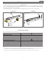
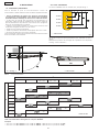
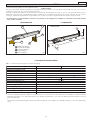
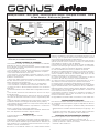
Automazione ACTION
Le presenti istruzioni sono valide per il seguente modello:
GENIUS ACTION
L’automazione ACTION, consente di automatizzare cancelli a battente residenziali con ante fino a 1,8 m di lunghezza con apertura
massima di 100°.
È costituita da attuatori lineari elettromeccanici irreversibili, alimentati a 12 Vdc, abbinati ognuno ad un'apparecchiatura elettroni-
ca. Il sistema irreversibile garantisce il blocco meccanico del cancello quando il motore non è in funzione. Uno sblocco manuale rende
manovrabile il cancello in caso di necessità.
L'automazione ACTION è stata progettata e costruita per controllare l’accesso veicolare. Evitare qualsiasi altro diverso utilizzo.
1. DESCRIZIONE 2. DIMENSIONI
3. CARATTERISTICHE TECNICHE
Tab. 1 - Caratteristiche tecniche operatore ACTION
(1)
La batteria carica permette di eseguire mediamente 10 cicli consecutivi. Il tempo di recupero (ricarica batteria) è di circa 10' per
ogni ciclo eseguito. Con temperatura basse (< 0°C) i cicli consecutivi si possono ridurre di oltre il 50%.
(2)
La protezione termica software permette di eseguire 30 cicli consecutivi. Il tempo di recupero è di 2 minuti per ogni ciclo eseguito.
• quote in mm
Operatore ACTION
Attacco posteriore
Attacco anteriore
Sblocco
Boccola per staffa

2
ITALIANO
520
Fig.3
Fig.4
D
88 ÷ 91
92 ÷ 97
98 ÷ 102 103 ÷ 107
108 ÷ 113
114 ÷ 119
120 ÷ 126
30 ÷ 39
40 ÷ 49
50 ÷ 59
60 ÷ 69
70 ÷ 79
80 ÷ 89
90 ÷ 99
100 ÷ 109
110 ÷ 119
120 ÷ 129
130 ÷ 140
B
90°
100°
90°
100°
90°
90°
90°
100°
90°
90°
100°
100°
90°
90°
100°
100°
90°
90°100°
100°
90°
90°
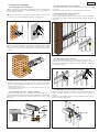
4. INSTALLAZIONE
4.1. Verifiche preliminari
Per la sicurezza e per un corretto funzionamento dell’automazio-
ne, verificare l’esistenza dei seguenti requisiti:
• Prevedere l'installazione dei contenitori delle apparecchiature
elettroniche (vedere istruzione relativa) ad una distanza dagli
attuatori tale per cui non si debba in alcun caso allungare il
cavo del motore.
• La struttura del cancello deve essere idonea per essere auto-
matizzata. In particolare verificare che sia sufficientemente ro-
busta e rigida e che dimensioni e massa siano conformi a quelle
indicate nelle caratteristiche tecniche.
• Verificare il movimento regolare e uniforme delle ante, privo di
attriti irregolari durante tutta la corsa.
• Verificare il buono stato delle cerniere.
• Verificare la presenza degli arresti meccanici di finecorsa.
• Rimuovere eventuali serrature e chiavistelli.
Si raccomanda di effettuare gli eventuali interventi fabbrili prima
d'installare l'automazione.
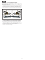
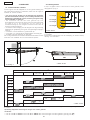
4.2. Quote d'installazione
Le quote Z possibili da utilizzare sono 4 come indicato in Fig. 3.
Non tagliare assolutamente la staffa posteriore per realizzare la
quota A (Fig. 4).
Determinare la posizione di montaggio dell'operatore facendo
riferimento alla Fig. 4 e alla Tab. 2.
Tab.2 - Quote installazione
Nella tabella l'intersezione delle quote D e B (vedi Fig. 4) determina il foro di fissaggio della staffa che occorre utilizzare.
Nota: Non sono utilizzabili le intersezioni prive di figure.
Esempio:
• con una quota D di 45mm e una quota B di 100mm occorre utilizzare il 4° foro (apertura di 100°)
• con una quota D di 45mm e una quota B di 105mm occorre utilizzare il 4° foro (apertura di 90° )
• quote in mm
• quote in mm
Z = vedi Fig. 3
1° foro
2° foro
4° foro
3° foro
• quote in mm

3
ITALIANO
3
1
2
Fig.5
Fig.6
Fig.7
Fig.8
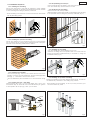
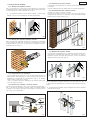
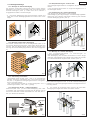
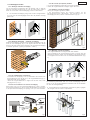
4.3. Sequenza di montaggio
4.3.1 Montaggio attacco posteriore
Fissare, verificando la perfetta orizzontalità, l'attacco posteriore al
pilastro tramite saldatura o adeguati tasselli (Fig. 5), rispettando le
quote indicate in Tab.2.
!!
!!
! L'attacco posteriore non deve mai essere tagliato e deve esse-
re rivolto con i punti di fissaggio a pilastro verso il basso.
4.3.2 Montaggio operatore-attacco posteriore
Fissare l'operatore all'attacco posteriore con il dado e la rondella
(Fig. 6), facendo attenzione ad innestare correttamente la parte
smussata del perno nel foro dell'attacco posteriore determinato
in Tab. 2.
4.3.3 Preparazione degli operatori
• Verificare che il perno (Fig. 7 Rif. 3) sia a battuta nella parte
anteriore dell'operatore; in caso contrario ruotare la chiave di
sblocco, inserita nell'apposita sede (Fig. 7), in senso orario fino al
termine della sua corsa.
• Ruotare la chiave di sblocco in senso antiorario per 6-7 giri,
come indicato in Fig. 7.
4.3.4 Inserimento boccola - attacco anteriore
Inserire la boccola (Fig. 7 Rif. 1) nell'attacco anteriore (Fig. 7 Rif. 2).
Il fermo meccanico sulla boccola dovrà coincidere con la scana-
latura del perno dell'operatore. Innestare il perno (Fig. 7 Rif. 3) nella
boccola.
4.3.5 Riposizionamento perno anteriore
• Ruotare la chiave di sblocco in senso orario fino al termine della
sua corsa.
• Ruotare la chiave di sblocco in senso antiorario per 3 giri.
4.3.6 Posizionamento attacco anteriore
• Portare l'anta in posizione chiusa.
• Appoggiare l'attacco all'anta e tracciare i punti di fissaggio,
verificando la perfetta orizzontalità dell'operatore e dell'attac-
co (Fig. 8).
4.3.7 Montaggio attacco anteriore
• Ruotare la chiave di sblocco di 2-3 giri in senso antiorario.
• Sfilare l'attacco dall'operatore per fissarlo all'anta. L'attacco
può essere direttamente saldato oppure avvitato utilizzando
inserti filettati (Fig. 9),
4.3.8 Montaggio operatore-attacco anteriore
Fissare l'operatore all'attacco anteriore come indicato in Fig. 10 e
ruotare la chiave di sblocco in senso orario fino alla battuta di
chiusura.
L'operatore è irreversibile; evitare quindi qualsiasi tentativo di mo-
vimento manuale delle ante.
Fig.9
Fig.10
Sblocca
Blocca
Blocca

4
ITALIANO
Fig.11
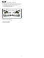
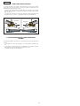
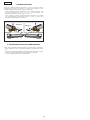
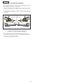
5. FUNZIONAMENTO MANUALE
Nel caso sia necessario azionare manualmente il cancello a cau-
sa di disservizio dell'automazione, agire sul dispositivo di sblocco
come segue:
• Inserire la chiave a brugola in dotazione nella parte anteriore
dell'operatore e ruotarla in senso antiorario per 5-6 giri (Fig. 11 Rif.
1).
• Sollevare l'operatore dalla parte anteriore disaccoppiandolo
dall'attacco (Fig. 11 Rif. 2) e sfilare la chiave di sblocco.
6. RIPRISTINO DEL FUNZIONAMENTO NORMALE
Qualora si voglia ribloccare il cancello agire come segue:
• Riposizionare l'operatore sull'attacco anteriore (Fig. 10);
• Inserire e ruotare le chiave di sblocco in senso orario fino a
portare l'operatore in battuta di chiusura;
• Sfilare la chiave di sblocco.
1
2
1
2
Sblocca
Sblocca

5
ENGLISH
1
2
3
5
4
5
0
80
6
0
5
9
8
5
5
Fig.1
Fig.2
LEDOMyrettabNOITCAremrofsnartNOITCA
ylppusrewoP cdV21
)W(rewopdebrosbadetaR 84
)N(ecrofcitatsxaM 0001
).ces/.m
c(deepsraenileerf-daoL 2,3
)mm(ekortsevitceffedoR 082
selcycevitucesnoC 01~
)1(
03
)2(
emityrevoceR elcycdetelpmochcaerof'01~
)1(
elcycdetelpmochcaerof'2
)2(
)C°(erutarepmettneibmagnitarepO 55+÷02-
)gK(thgiewrotarepO 2,2
ssalcnoitcetorP 44PI
)m(htgnelxamfaeL 08,1
)gk
(thgiewxamfaeL 052
)mm(DxHxLsnoisnemidllarevorotarepO 2.gifidev
)m(elbacrewoprotarepofohtgneL 7,0 )DEIFIDOM
EBTONNAC(
ACTION automated system
These instructions apply to the following model:
GENIUS ACTION
The ACTION automated system can automate residential swing gates with leaves of up to 1.8 m in length with 100° max. opening.
It consists of non-reversing electro-mechanical articulated operators, powered by 12 Vdc, and each operator is coupled to a control
unit. The non-reversing system guarantees the gate will automatically lock when the motor is not operating. A release system enables
the gate to be moved by hand in case of malfunction.
The ACTION automated system was designed and built for controlling vehicle access. Do not use for any other purpose.
1. DESCRIPTION 2. DIMENSIONS
3. TECHNICAL SPECIFICATIONS
Tab. 1 - Technical specifications of ACTION operator
(1)
10 consecutive cycles can be averagely performed with charged battery. The recovery time (battery recharge) is approx. 10' each
cycle performed. The consecutive cycles could be reduced by over 50% at low temperatures (< 0°C).
(2)
30 consecutive cycles can be performed with software thermal protection. Recovery time is 2' each cycle performed.
• Dimensions in mm
햲햲
햲햲
햲 ACTION operator
햳햳
햳햳
햳 Rear fitting
햴햴
햴햴
햴 Front fitting
햵햵
햵햵
햵 Release
햶햶
햶햶
햶 Bracket bush

6
ENGLISH
520
Fig.3
Fig.4
D
88 ÷ 91
92 ÷ 97
98 ÷ 102 103 ÷ 107
108 ÷ 113
114 ÷ 119
120 ÷ 126
30 ÷ 39
40 ÷ 49
50 ÷ 59
60 ÷ 69
70 ÷ 79
80 ÷ 89
90 ÷ 99
100 ÷ 109
110 ÷ 119
120 ÷ 129
130 ÷ 140
B
90°
100°
90°
100°
90°
90°
90°
100°
90°
90°
100°
100°
90°
90°
100°
100°
90°
90°100°
100°
90°
90°
4. Installation
4.1. Preliminary checks
To ensure safety and an efficiently operating automated system,
make sure the following conditions are observed:
• The enclosures of the control boards (see relevant instructions)
should be installed at a distance from the operators not requi
ring the motor cable to be extended.
• The structure of the gate must be suitable for being automated.
In particular, check that the structure is sufficiently strong and
rigid, and that its dimensions and weight conform to those
indicated in the technical specifications.
• Make sure that the leaves move uniformly and correctly, without
any irregular friction during their entire travel.
• Make sure that the hinges are in good condition.
• Check if the mechanical stops of the limit-switches are fitted.
• Remove any locks and lock bolts.
We advise you to have any metalwork carried out before the
automated system is installed.
4.2. Installation dimensions
There are 4 possible installation dimensions Z as shown in Fig. 3.
Do not , on any account, cut the rear bracket to obtain dimension
A (Fig. 4).
Establish the installation position of the operator by referring to Fig.
4 and Table 2.
Tab. 2 - Installation dimensions
The intersection of dimensions D and B (see Fig. 4) in the table determines which fixing hole on the bracket should be used.
Note: Intersections without figures cannot be used.
Example:
• For a D dimension of 45 mm and a B dimension of 100 mm, use the 4th hole (100° opening).
• For a D dimension of 45 mm and a B dimension of 105 mm, use the 4th hole (90° opening).
Z = see Fig. 3
• Dimensions in mm
• Dimensions in mm
• Dimensions in mm
1
st
hole
4
th
hole
3
rd
hole
2
nd
hole

7
ENGLISH
3
1
2
Fig.5
Fig.6
Fig.7
Fig.8
Fig.9
Fig.10
4.3. Installation sequence
4.3.1 Installing the rear fitting
Secure the rear fitting to the pillar by welding or using suitable
expansion plugs (Fig. 5), observing the dimension as shown in Table
2 and checking if the fitting is perfectly horizontal.
!The rear fitting must never be cut and it must face downwards
with its pillar fixing points.
4.3.2 Installing the operator-rear fitting
Secure the operator to the rear fitting, with the nut and washer
(Fig. 6), taking care to correctly fit the chamfered part of the pin in
the hole of the rear fitting determined in Table 2.
4.3.3 Preparing the operators
• Check if the pin (Fig. 7 Ref. 3) is in contact with the front of the
operator. If it is not, turn the release key - fitted in the appropriate
seat (Fig. 7) - clockwise to the end of its travel.
• Turn the release key anti-clockwise for 6-7 turns as shown in Fig.
7.
4.3.4 Inserting the bush - front fitting
Insert the bush (Fig. 7 Ref. 1) in the front fitting (Fig. 7 Ref. 2). The
mechanical stop on the bush must coincide with the pin groove
of the operator. Fit the pin (Fig. 7 Ref. 3) in the bush.
4.3.5 Re-positioning the front pin
• Turn the release key clockwise to the end of its travel.
• Turn the release key anti-clockwise for 3 turns.
4.3.6 Positioning the front fitting
• Take the leaf to its closed position.
• Rest the fitting on the leaf and mark out the fixing points checking
if the operator and the fitting are perfectly horizontal (Fig. 8).
4.3.7 Installing the front fitting
• Turn the release key anti-clockwise for 2-3 turns.
• Remove the fitting from the operator and fit it on the leaf. The
fitting can be either welded directly or screwed on, using the
threaded inserts (Fig. 9).
4.3.8 Installing the operator-front fitting
Fasten the operator to the front fitting as shown in Fig. 10 and turn
the release key clockwise to the closing stop position.
!The operator is non-reversing, so do not, on any account, try to
move the leaves by hand.
Lock
Unlock
Lock

8
ENGLISH
Fig.11
5. MANUAL OPERATION
If the gate has to be moved manually due to a malfunction of the
automated system, use the release device as follows:
• Fit the supplied Allen wrench in the front part of the operator
and turn it anti-clockwise for 5-6 turns (Fig. 11 Ref. 1).
• Lift the operator by its front end, detaching it from the fitting (Fig.
11 Ref.2) and remove the release key.
6. RESTORING NORMAL OPERATION MODE
Procedure to relock the gate:
• Re-position the operator on the front fitting (Fig. 10);
• Fit and turn the release key clockwise until the operator reaches
the closing stop position.
• remove the release key.
1
2
1
2
Unlock
Unlock

9
FRANÇAIS
1
2
3
5
4
5
0
80
6
0
5
9
8
5
5
Fig.1
Fig.2
ELEDOMeirettabNOITCAruetamrofsnartNOITCA
noitatnemilA cdV21
)W(eébrosbaelanimonecnassiuP 84
)N(ixameuqitatse
croF 0001
)s/mc(edivàeriaénilessetiV 2,3
)mm(egitaledelituesruoC 082
sfitucésnocselcyC 01~
)1(
03
)2(
noitarépucéredspmeT éutceffeelcyceuqahcruop'01~
)1(
éutceffeelcyceuqahcruop'2
)2(
)C°(noitasilitu’derutarépmeT 55+÷02-
)gk(ruetaréposdioP 2,2
noitcetorpedérgeD 44PI
)m(liatnavixamrueugnoL 08
,1
)gK(liatnavixamsdioP 052
)mm(PxHxLruetarépotnemerbmocnE 2.gifriov
)m(ruetaréponoitatnemila’delbâcrueugn
oL 7,0 )ELBAIFIDOMNON(
Automatisme ACTION
Ces instructions sont valables pour le modèle suivant:
GENIUS ACTION
L’automatisme ACTION, permet d’automatiser les portails battants domestiques avec des vantaux jusqu’à 1,8 m de longueur avec
une ouverture maximum de 100°
Il est constitué par des opérateurs articulés électromécaniques irréversibles, alimentés à 12 Vcc, associé chacun à une armoire
électronique. Le système irréversible garantit le blocage mécanique du portail quand le moteur n’est pas en fonction. Un déverrouillage
manuel permet de manœuvrer le portail en cas de dysfonctionnement.
L’automatisme ACTION a été conçu et construit pour contrôler l’accès des véhicules. Eviter toute autre utilisation.
1. DESCRIPTION 2. DIMENSIONS
3. CARACTERISTIQUES TECHNIQUES
Tabl. 1 - Caractéristiques techniques de l’opérateur ACTION
(1)
La batterie chargée permet d’exécuter immédiatement 10 cycles consécutifs. Le temps de récupération (recharge batterie) est
d’environ 10 mn pour chaque cycle exécuté. A des températures basses(< 0°C) les cycles consécutifs peuvent diminuer de plus de
50%.
(2)
La protection thermique du logiciel permet d’exécuter 30 cycles consécutifs. Le temps de récupération est de 2 mn pour chaque
cycle exécuté.
• cotes en mm
Opérateur ACTION
Patte d’attache postérieure
Patte d’attache antérieure
Déblocage
Douille pour patte

10
FRANÇAIS
520
Fig.3
Fig.4
D
88 ÷ 91
92 ÷ 97
98 ÷ 102 103 ÷ 107
108 ÷ 113
114 ÷ 119
120 ÷ 126
30 ÷ 39
40 ÷ 49
50 ÷ 59
60 ÷ 69
70 ÷ 79
80 ÷ 89
90 ÷ 99
100 ÷ 109
110 ÷ 119
120 ÷ 129
130 ÷ 140
B
90°
100°
90°
100°
90°
90°
90°
100°
90°
90°
100°
100°
90°
90°
100°
100°
90°
90°100°
100°
90°
90°
4. INSTALLATION
4.1. Vérifications préliminaires
Pour la sécurité et pour un fonctionnement correct de
l’automatisme, vérifier l’existence des conditions requises suivantes:
• Prévoir l’installation des boîtiers des armoires électroniques
(voir instruction correspondante) à une distance des opérateurs
permettant d’éviter d’allonger en aucun cas le câble du moteur.
• La structure du portail doit permettre l’automatisation. En
particulier, vérifier qu’elle est suffisamment robuste et rigide et
que les dimensions et le poids sont conformes à ceux qui figurent
dans les caractéristiques techniques.
• Vérifier le mouvement régulier et uniforme des vantaux, sans
frottements irréguliers durant toute la course.
• Vérifier le bon état des charnières.
• Vérifier la présence des butées mécaniques de fin de course.
• Démonter les serrures et les verrous éventuels.
On recommande d’effectuer toutes les interventions de ferronnerie
avant d’installer l’automatisme.
4.2. Cotes d’installation
Le cotes Z utilisables sont au nombre de 4, d’après la Fig. 3.
Ne jamais couper la patte postérieure pour atteindre la cote A
(Fig. 4).
Déterminer la position de montage de l’opérateur en se reportant
à la Fig. 4 et au tableau 2.
Tabl. 2 - Cotes d’installation
Dans le tableau, l’intersection des cotes D et B (voir Fig. 4) détermine le trou de fixation de la patte à utiliser.
Note: Les intersections sans figures ne sont pas utilisables.
Exemple:
• avec une cote D de 45mm et une cote B de 100mm , utiliser le 4e trou (ouverture de 100°)
• avec une cote D de 45mm et une cote B de 105mm , utiliser le 4e trou (ouverture de 90°)
Z = voir Fig. 3
• cotes en mm
• cotes en mm
• cotes en mm
4e trou
3e trou
2e trou
1er trou

11
FRANÇAIS
3
1
2
Fig.5
Fig.6
Fig.7
Fig.8
Fig.9
Fig.10
4.3. Séquence de montage
4.3.1 Montage de la patte d’attache postérieure
Fixer, en vérifiant l’horizontalité parfaite, la patte d’attache
postérieure au pilier au moyen d’une soudure ou de tasseaux
adéquats (Fig. 5), en respectant les cotes indiquées dans le Tabl.
2.
! La patte d’attache postérieure ne doit jamais être coupée et
doit être tournée avec les points de fixation au pilier vers le bas.
4.3.2 Montage de l’opérateur-patte d’attache postérieure
Fixer l’opérateur à la patte d’attache postérieure avec l’écrou et
la rondelle (Fig. 6),en veillant à embrayer correctement la partie
arrondie de l’axe dans le trou de la patte d’attache postérieure,
déterminée dans le Tab. 2.
4.3.3 Préparation des opérateurs
• Vérifier que l’axe (Fig. 7 Réf. 3) est contre la partie antérieure de
l’opérateur; dans le cas contraire, tourner la clé de déverrouillage,
introduite dans son logement (Fig. 7), en sens horaire jusqu’au
bout de sa course.
• Tourner la clé de déverrouillage de 6-7 tours en sens inverse
horaire d’après la Fig. 7.
4.3.4 Introduction de la douille - patte d’attache antérieure
Introduire la douille (Fig. 7 Réf. 1) dans la patte d’attache antérieure
(Fig. 7 Réf. 2). L’arrêt mécanique sur la douille devra coïncider
avec la rainure de l’axe de l’opérateur. Introduire l’axe (Fig. 7 Réf.
3) dans la douille.
4.3.5 Repositionnement de l’axe antérieur
• Tourner la clé de déverrouillage en sens horaire jusqu’au bout
de sa course.
• Tourner la clé de déverrouillage de 3 tours en sens inverse horaire.
4.3.6 Positionnement de la patte d’attache antérieure
• Amener le vantail en position fermée.
• Poser la patte d’attache contre le vantail et tracer les points de
fixation en vérifiant l’horizontalité parfaite de l’opérateur et de
la patte d’attache (Fig. 8).
4.3.7 Montage de la patte d’attache antérieure
• Tourner la clé de déverrouillage de 2-3 tours en sens inverse
horaire.
• Extraire la patte d’attache de l’opérateur pour le fixer au vantail.
La patte d’attache peut être directement soudée ou vissée en
utilisant des pièces intercalaires filetées (Fig. 9).
4.3.8 Montage de l’opérateur-patte d’attache antérieure
Fixer l’opérateur à la patte d’attache antérieure d’après la Fig.
10 et tourner la clé de déverrouillage en sens horaire jusqu’à la
butée de fermeture.
! L’opérateur est irréversible, éviter par conséquent toute
tentative d’actionnement manuel des vantaux.
Bloque
Debloque
Bloque

12
FRANÇAIS
Fig.11
5. FONCTIONNEMENT MANUEL
S’il faut actionner manuellement le portail en raison d’un
dysfonctionnement de l’automatisme, agir sur le dispositif de
déverrouillage comme suit:
• Introduire la clé à six pans creux fournie à l’avant de l’opérateur
et la tourner de 5-6 tours en sens inverse horaire (Fig. 11 Réf. 1).
• Soulever l’opérateur par l’avant en le désassemblant de la
patte d’attache (Fig. 11 Réf. 2) et extraire la clé de déverrouillage.
6. RETABLISSEMENT DU FONCTIONNEMENT NORMAL
Si on souhaite de nouveau bloquer le portail, agir comme suit:
• Replacer l’opérateur sur la patte d’attache antérieur (Fig. 10);
• Introduire et tourner la clé de déverrouillage en sens horaire
pour amener l’opérateur sur la butée de fermeture;
• Extraire la clé de déverrouillage.
1
2
1
2

13
ESPAÑOL
1
2
3
5
4
5
0
80
6
0
5
9
8
5
5
Fig.1
Fig.2
OLEDOMaíretabNOITCArodamrofsnartNOITCA
nóicatnemilA cdV21
)W(adibrosbalanimonaicnetoP 84
)N(xámacitátseazreu
F 0001
).ges/.mc(oícavnelaenildadicoleV 2,3
)mm(ogatsávledlitúarerraC 082
sovitucesnocsolciC 01~
)1(
03
)2(
nóicarepuceredopmeiT odazilaerolcicadacrop'01~
)1(
odazilaerolcicadacrop'2
)2(
)C°(etneibmaarutarepmeT 55+÷02-
)gK(rodarepooseP 2,2
nóiccetorpedodarG 44PI
)m(ajoh.xámdutignoL 08,1
)gK(ajoh
.xámoseP 052
)mm(PxHxLrodarepo.xámsenoisnemiD 2.gifesaév
)m(rodareponóicatnemilaedelbacleddutignoL 7,0 )ELB
ACIFIDOMON(
Automación ACTION
Las presentes instrucciones son válidas para el siguiente modelo:
GENIUS ACTION
La automación ACTION permite automatizar cancelas de batientes residenciales con hojas de hasta 1,8 m de longitud con apertura
máxima de 100°.
Está constituida por actuadores articulados electromecánicos irreversibles, alimentados a 12 Vdc, combinados cada uno a un
equipo electrónico. El sistema irreversible garantiza el bloqueo mecánico de la cancela cuando el motor no está en funcionamiento.
Un desbloqueo manual permite maniobrar la cancela en caso de avería.
La automación ACTION ha sido proyectada y fabricada para controlar el acceso de vehículos. Eviten cualquier otro uso.
1. DESCRIPCIÓN 2. DIMENSIONES
3. CARACTERÍSTICAS TÉCNICAS
Tab. 1 - Características técnicas operador ACTION
(1)
La batería cargada permite realizar una media de 15 ciclos consecutivos. El tiempo de recuperación (recarga de la batería) es de
aproximadamente 10' para cada ciclo realizado. Con bajas temperaturas (< 0°C), los ciclos consecutivos se pueden reducir en más
de un 50%.
(2)
La protección térmica software permite realizar 30 ciclos consecutivos. El tiempo de recuperación es de 2' para cada ciclo
realizado.
햲햲
햲햲
햲 Operador ACTION
햳햳
햳햳
햳 Empalme posterior
햴햴
햴햴
햴 Empalme anterior
햵햵
햵햵
햵 Desbloqueo
햶햶
햶햶
햶 Casquillo para abrazadera
• cotas en mm

14
ESPAÑOL
520
Fig.3
Fig.4
D
88 ÷ 91
92 ÷ 97
98 ÷ 102 103 ÷ 107
108 ÷ 113
114 ÷ 119
120 ÷ 126
30 ÷ 39
40 ÷ 49
50 ÷ 59
60 ÷ 69
70 ÷ 79
80 ÷ 89
90 ÷ 99
100 ÷ 109
110 ÷ 119
120 ÷ 129
130 ÷ 140
B
90°
100°
90°
100°
90°
90°
90°
100°
90°
90°
100°
100°
90°
90°
100°
100°
90°
90°100°
100°
90°
90°
4° orificio
3° orificio
2° orificio
1° orificio
4. INSTALACIÓN
4.1. Comprobaciones preliminares
Para obtener la máxima seguridad y para un correcto
funcionamiento de la automación, compruebe que se verifiquen
los siguientes requisitos:
• Prever la instalación de los contenedores de los equipos
electrónicos (véanse correspondientes instrucciones) a una
distancia tal de los operadores que evite que se tenga que
alargar el cable del motor.
• La estructura de la cancela debe ser la adecuada para ser
automatizada. Más concretamente, compruebe que sea lo
suficientemente robusta y rígida y que las dimensiones y la masa
sean conformes con las indicadas en las características técnicas.
• Compruebe el movimiento regular y uniforme de las hojas, no
debe presentar roces irregulares durante todo el recorrido.
• Compruebe que las bisagras estén en buen estado.
• Compruebe que estén presentes los topes mecánicos de fin de
carrera.
• Quite las posibles cerraduras y cerrojos.
Se aconseja efectuar las eventuales intervenciones en los herrajes
antes de instalar la automación.
4.2. Cotas de instalación
Las cotas Z que se pueden utilizar son 4, tal y como se indica en la
Fig. 3.
No cortar absolutamente la abrazadera posterior para realizar la
cota A (Fig. 4).
Determine la posición de montaje del operador tomando como
referencia la Fig. 4 y la tabla 2.
Tab. 2 - Cotas de instalación
En la tabla la intersención de las cotas D y B (véase Fig. 4) determina el orificio de fijación de la abrazadera que hay que utilizar.
Nota: No se utilizan las intersecciones sin figuras.
Ejemplo:
• con una cota D de 45mm y una cota B de 100mm hay que utilizar el 4° orificio (apertura de 100°)
• con una cota D de 45mm y una cota B de 105mm hay que utilizar el 4° orificio (apertura de 90°)
• cotas en mm
• cotas en mm
• cotas en mm
Z = véase Fig. 3

15
ESPAÑOL
3
1
2
Fig.5
Fig.6
Fig.7
Fig.8
Fig.9
Fig.10
4.3. Secuencia de montaje
4.3.1 Montaje del empalme posterior
Fije, comprobando la perfecta horizontalidad, el empalme
posterior al pilar por medio de soldadura o adecuados tacos (Fig.
5), respetando las cotas indicadas en la Tab.2.
! El empalme posterior nunca debe cortarse, y ha de estar
dirigido con los puntos de fijación al pilar hacia abajo.
4.3.2 Montaje del operador-empalme posterior
Fije el operador al empalme posterior con la tuerca y la arandela
(Fig. 6), prestando atención a acoplar correctamente la parte
avellanada del perno en el orificio del empalme posterior
determinado en la Tab. 2.
4.3.3 Preparación de los operadores
• Compruebe que el perno (Fig. 7 Ref. 3) esté hasta el tope en la
parte anterior del operador, en caso contrario gire la llave de
desbloqueo, introducida en su alojamiento (Fig. 7), en sentido
horario hasta el final de su carrera.
• Gire 6-7 vueltas la llave de desbloqueo en sentido antihorario,
como se indica en la Fig. 7.
4.3.4 Introducción casquillo - empalme anterior
Introduzca el casquillo (Fig. 7 Ref. 1) en el empalme anterior (Fig. 7
Ref. 2). El bloqueo mecánico situado sobre el casquillo deberá
coincidir con la ranura del perno del operador. Acople el perno
(Fig. 7 Ref. 3) en el casquillo.
4.3.5 Colocación del perno anterior
• Gire la llave de desbloqueo en sentido horario hasta el final de
su carrera.
• Gire 3 vueltas la llave de desbloqueo en sentido antihorario.
4.3.6 Posicionamiento del empalme anterior
• Coloque la hoja en posición cerrada.
• Apoye el empalme a la hoja y trace los puntos de fijación,
comprobando que tanto el operador como el empalme estén
perfectamente horizontales (Fig. 8).
4.3.7 Montaje del empalme anterior
• Gire la llave de desbloqueo 2-3 vueltas en sentido antihorario.
• Extraiga el empalme del operador para fijarlo a la hoja. El
empalme puede soldarse directamente o bien atornillado
utilizando insertos roscados (Fig. 9).
4.3.8 Montaje del operador-empalme anterior
Fije el operador al empalme anterior como se indica en la Fig. 10
y gire la llave de desbloqueo en sentido horario hasta el tope de
cierre.
! El operador es irreversible, evite cualquier intento de movimiento
manual de las hojas.
Bloquear
Desbloquear
Bloquear

16
ESPAÑOL
1
2
1
2
Fig.11
5. FUNCIONAMIENTO MANUAL
Si fuera necesario accionar manualmente la cancela a causa
de avería de la automación, hay que utilizar el dispositivo de
desbloqueo del siguiente modo:
• Introduzca la llave Allen suministrada en dotación en la parte
anterior del operador y gírela 5-6 vueltas en sentido antihorario
(Fig. 11 Ref. 1).
• Levante el operador por la parte anterior, desacoplándolo del
empalme (Fig. 11 Ref. 2) y extraiga la llave de desbloqueo.
6. RESTABLECIMIENTO DEL FUNCIONAMIENTO
NORMAL
Si desea bloquear de nuevo la cancela proceda del siguiente
modo:
• Coloque de nuevo el operador en el empalme anterior (Fig.
10);
• introduzca y gire la llave de desbloqueo en sentido horario
hasta llevar el operador hasta el tope de cierre;
• extraiga la llave de desbloqueo.
Desbloquear
Desbloquear

17
DEUTSCH
1
2
3
5
4
5
0
80
6
0
5
9
8
5
5
Abb.1
Abb.2
LLEDOMeirettaBNOITCArotamrofsnarTNOITCA
gnugrosreV cdV21
)W(hcuarbrevsgnutsielnneN 84
)N(tfarKehcsitats.xaM 0
001
).keS/.mc(fualreeLmitiekgidniwhcsegraeniL 2,3
)mm(stfahcSsedbuhztuN 082
nelkyZedneglofrednaniefuA 01~
)1(
03
)2(
tiezsgnulohrE sulkyZnetrhüfegsuanedejrüf'01~
)1(
sulkyZnetrhüfegsuanedejrüf'2
)2(
)C°(trosgnulletsfuAmarutarepmeT 55+÷02-
)gK(sbeirtnAsedthciweG 2,2
traztuhcS 44PI
)m(egnällegülF.xaM 08,1
)gK
(thciweglegülF.xaM 052
)mm(TxHxLsbeirtnAsednegnussembA 2.bbAeheis
)m(beirtnAlebaksgnugrosreVegnäL 7,0 )RABR
EIZIFIDOMTHCIN(
Automation ACTION
Die vorliegenden Anweisungen gelten für das nachfolgende Modell:
GENIUS ACTION
Die Automation ACTION erlaubt die Automatisierung von Flügeltoren für Wohngebäude mit Flügeln mit einer Länge von bis zum 1,8 m
und einer maximalen Öffnung von 100°.
Sie besteht aus elektromechanischen irreversiblen Gelenkantrieben, die mit 12 Vdc gespeist werden. Jeder Antrieb ist an ein elektronisches
Steuergerät angeschlossen. Das irreversible System gewährleistet die mechanische Sperre des Tors bei ausgeschaltetem Motor. Eine
manuelle Entriegelung ermöglicht die Bewegung des Tors bei Betriebsstörungen.
Die Automation ACTION wurde für die Zufahrtskontrolle entwickelt und hergestellt. Jeder andere Einsatz ist zu vermeiden.
1. BESCHREIBUNG 2. ABMESSUNGEN
3. TECHNISCHE EIGENSCHAFTEN
Tab. 1 - Technische Eigenschaften Antrieb ACTION
(1)
Mit geladener Batterie können im Durchschnitt 10 aufeinanderfolgende Zyklen durchgeführt werden. Die Erholungszeit (Aufladung
der Batterie) beträgt ca. 10' je durchgeführten Zyklus. Bei niedrigen Temperaturen (< 0°C) können sich die aufeinanderfolgenden
Zyklen um mehr als 50% reduzieren
(2)
Mit dem Software-Thermoschutz können 30 aufeinanderfolgende Zyklen durchgeführt werden. Die Erholungszeit beträgt 2' je
durchgeführten Zyklus.
• Maße in mm
햲햲
햲햲
햲 Antrieb ACTION
햳햳
햳햳
햳 Hintere Befestigung
햴햴
햴햴
햴 Vordere Befestigung
햵햵
햵햵
햵 Entriegelung
햶햶
햶햶
햶 Buchse für Bügel
La pagina si sta caricando...
La pagina si sta caricando...
La pagina si sta caricando...
La pagina si sta caricando...
La pagina si sta caricando...
La pagina si sta caricando...
La pagina si sta caricando...
La pagina si sta caricando...
La pagina si sta caricando...
La pagina si sta caricando...
La pagina si sta caricando...
La pagina si sta caricando...
-
 1
1
-
 2
2
-
 3
3
-
 4
4
-
 5
5
-
 6
6
-
 7
7
-
 8
8
-
 9
9
-
 10
10
-
 11
11
-
 12
12
-
 13
13
-
 14
14
-
 15
15
-
 16
16
-
 17
17
-
 18
18
-
 19
19
-
 20
20
-
 21
21
-
 22
22
-
 23
23
-
 24
24
-
 25
25
-
 26
26
-
 27
27
-
 28
28
-
 29
29
-
 30
30
-
 31
31
-
 32
32


in altre lingue
- français: Genius Action Mode d'emploi
- español: Genius Action Instrucciones de operación
- Deutsch: Genius Action Bedienungsanleitung
- Nederlands: Genius Action Handleiding
Documenti correlati
-
Genius Linear Istruzioni per l'uso
-
-
-
-
-
-
-