
cover
Climbing Technology by Aludesign S.p.A. via Torchio 22
24034 Cisano B.sco BG ITALY www.climbingtechnology.com 1/29
Member of IST12-2D657CT_rev.5 04-22
BE UP
EN Belay / Rappel device.
IT Assicuratore / Discensore.
FR Assureur / Descendeur.
DE Sicherungs / Abseilgerät.
ES Asegurador / Descensor.
PT Segurador / Descensor.
SE Säkrings- / Nedfirandeanordning.
FI Varmistin / Laskeutumislaite.
NO Sikringsinnretning / Nedstigningsinnretning.
DK Sikring/Nedfiring.
NL Zekeringsapparaat / Afdaalapparaat.
CZ Jistící / Slaňovací zařízení.
CN 保护/下降 设备
MADE IN ITALY
EN 15151-2:2012 TYPE 4
REGISTERED DESIGN
ZL 201430507247.3
G
=+S

drawings
Climbing Technology by Aludesign S.p.A. via Torchio 22
24034 Cisano B.sco BG ITALY www.climbingtechnology.com 2/29
Member of IST12-2D657CT_rev.5 04-22
TECHNICAL DATA
MODEL BE UP
REF. No. 2D657
WEIGHT 85 g
ROPE
FOR USE WITH ROPES EN 892:
½ half / twin ropes Ø 7.3÷9 mm
1 single rope Ø 8.5 ÷ 10.5 mm.
ATTENTION! The term “rope” can mean
one or two strands of rope. When using half
or twin ropes, each strand of rope must pass
through its separate rope slot.
ATTACHMENT
/ BRAKING
KARABINER
You must use a locking
gate wide-base HMS
karabiner. We
recommended to use
our screw gate karabiner
Concept SGL HC which
has an anti-wear surface
and a lever that prevents
the danger of cross loading.
TEST MADE BY
VVUU a.s.
TESTING LABORATORY
Pikartska 1337/7 716 07
Ostrave - Radvanice
CZECH REPUBLIC
12LEGEND
2.1 - leader 2.2 - second 2.3 - lowering
2.4 - hand 2.5 - anchor 2.6 - fall 2.7 - resting
H2O SOAP
MAX
30°C
WARNINGS
3
0 kN
654
2
3
1
7
15
14
12
11
10
9
8
CB
E
F
G
13
A
D
Side A: belaying the leader, top roping, abseiling.
Side B: belaying 1-2 seconds.
4.1 4.4 4.5
4.2 - SIDE A 4.3 - SIDE B
4NOMENCLATURE / MARKING

Climbing Technology by Aludesign S.p.A. via Torchio 22
24034 Cisano B.sco BG ITALY www.climbingtechnology.com 3/29
Member of IST12-2D657CT_rev.5 04-22
NO!
NO!
NO!
OK!
NO!
NO!
OK!
Before belaying the belayer must: belay him/herself; verify that that Be Up functions properly; verify that the lead climber’s knot is correct; check that the rope is properly
untangled and has a knot at the end; fi nd a comfortable position that will not prevent you from belaying well.
5.1
SETUP 5.2
SETUP 5.3
SETUP 5.4
SETUP IS OK! 5.5 - OK 5.7
5.8
5.6 - ATTENTION!
Clip the belay karabiner to the
belay loop on the harness. Attach
the Be Up to the karabiner using
the connection cable.
Place a loop of rope through the C part of
the Be Up, referring to the symbols 3-4-5 en-
graved on the device.
Clip the rope to the karabiner
as shown. Close the karabiner
gate!
The system is OK.
From now on always hold
fi rmly the free end of the rope
in your hand!
5.9
5BELAYING THE LEADER
INSTALLATION / SETUP
BRAKE BRAKE
6.1 - STANDARD
BRAKING MODE 6.2 - REDUCED
BRAKING MODE
This mode is featured by a
greater braking effect and it is
recommended in most cases.
This mode is featured by a smal-
ler braking effect and it’s limited
to some conditions of use.
6ADJUSTING THE BRAKING

Climbing Technology by Aludesign S.p.A. via Torchio 22
24034 Cisano B.sco BG ITALY www.climbingtechnology.com 4/29
Member of IST12-2D657CT_rev.5 04-22
NO!
NO!
OK!
NO!
NO!
Be Up is manual braking device particularly useful for climbing on adventurous terrain, traditional climbing routes with the use of friends, nuts and pitons etc. and multipitch sport routes.
Attention! A safety check between the climber and the belayer is essential before start climbing.
7.1
GIVING SLACK 7.2
TAKING IN SLACK 7.3
ARRESTING A FALL 7.4
LOWERING 7.5
WARNING! 7.6
WARNING!
7.7
WARNING! 7.8
OK! 7.9
WARNING!
With one hand, bend and feed
the free end of the rope through
the Be Up. With the other pull
the climber’s rope through it.
With one hand pull and feed
the free end of the rope; with
the other pull the climber’s rope
towards the device.
Hold the free end of the rope
fi rmly in one or two hands and
pull it downwards. Be Up does
not automatically lock the rope.
Hold the rope fi rmly with both
hands and move them down the
rope one after another in order
to lower the companion to the
ground.
During all stages of belaying
(Fig. 7.1÷7.4) it is compul-
sory to always keep hold of
the free end of the rope.
In case of a leader fall, hold the free
end of the rope fi rmly in one or two
hands and pull it downwards. Don’t
hold the free end of the rope over the
device.
During all stages of belaying ne-
ver hold both sides of the rope as
shown. Danger of death!
When ascending a multi-pitch
route, the rope must pass through
a directional anchorage on the
belay point.
Always pass the leader rope
through a directional anchorage,
on the belay station.
If not, danger of death!
7BELAYING THE LEADER
NO!
NO!
OK!
NO!
NO!
Be Up is manual braking device particularly useful for climbing on adventurous terrain, traditional climbing routes with the use of friends, nuts and pitons etc. and multipitch sport routes.
Attention! A safety check between the climber and the belayer is essential before start climbing.
7.1
GIVING SLACK 7.2
TAKING IN SLACK 7.3
ARRESTING A FALL 7.4
LOWERING 7.5
WARNING! 7.6
WARNING!
7.7
WARNING! 7.8
OK! 7.9
WARNING!
With one hand, bend and feed
the free end of the rope through
the Be Up. With the other pull
the climber’s rope through it.
With one hand pull and feed
the free end of the rope; with
the other pull the climber’s rope
towards the device.
Hold the free end of the rope
fi rmly in one or two hands and
pull it downwards. Be Up does
not automatically lock the rope.
Hold the rope fi rmly with both
hands and move them down the
rope one after another in order
to lower the companion to the
ground.
During all stages of belaying
(Fig. 7.1÷7.4) it is compul-
sory to always keep hold of
the free end of the rope.
In case of a leader fall, hold the free
end of the rope fi rmly in one or two
hands and pull it downwards. Don’t
hold the free end of the rope over the
device.
During all stages of belaying ne-
ver hold both sides of the rope as
shown. Danger of death!
When ascending a multi-pitch
route, the rope must pass through
a directional anchorage on the
belay point.
Always pass the leader rope
through a directional anchorage,
on the belay station.
If not, danger of death!
7BELAYING THE LEADER

Climbing Technology by Aludesign S.p.A. via Torchio 22
24034 Cisano B.sco BG ITALY www.climbingtechnology.com 5/29
Member of IST12-2D657CT_rev.5 04-22
NO!
During all stages of belaying it is compulsory to always keep hold of the free
end of the rope.
8.1
SETUP 8.2
BELAYING 8.3
WARNING!
Before starting climbing, se-
tup the system as explained
in the fi gures 5.1÷5.4.
With one hand pull the free end
of the rope through the device,
with the other pull the climber’s
rope towards the device.
During all stages of belaying
(Fig. 8.1-8.2) it is compulsory to
always keep hold of the free end
of the rope.
8BELAYING IN TOP ROPE
Before abseiling you must: attach yourself to the anchor; prepare the rope for the abseil making sure it is not tangled and there is a knot in the end of the ropes; make a
prusik knot on the rope and connect it to your harness.
9.1
SETUP 9.2
TENSIONING 9.3
RELEASING THE SLING 9.4
ABSEILING
Connect the karabiner to the lanyard and clip
the Be Up to it. Place a loop of rope through
the Be Up and clip the rope to the karabiner
as shown. Close the karabiner gate.
Apply tension to the prusik knot to
remain suspended on the rope. With one hand hold fi rmly the free end of
the rope, than release the karabiner of the
lanyard from the belay station.
Manage the prusik knot in one hand so
that it does not tighten around the rope
and with the other hand control the speed
of descending.
9ABSEILING

Climbing Technology by Aludesign S.p.A. via Torchio 22
24034 Cisano B.sco BG ITALY www.climbingtechnology.com 6/29
Member of IST12-2D657CT_rev.5 04-22
STOP!
FRICTION FRICTION
NO!
NO!
NO!
This mode allows the belaying of one or two seconds simultaneously and independently.
After the setup and before the belaying you must test the system as shown in the fi gure 10.3.
10.1
SETUP 10.2
SETUP 10.3
TESTING 10.4 10.5
Connect a wide base HMS ka-
rabiner to the top of the anchor
and insert it in the Be Up. Place
a loop of rope through the C
part of the Be Up.
Clip the belay karabiner
through the rope and the
connection cable as shown.
Close the karabiner gate! Pull the rope down on the clim-
ber’s side, to make sure the sel-
f-locking system works.
10.6 10.7 10.8
10
BELAYING OF 1 OR 2 SECONDS
INSTALLATION / SETUP

Climbing Technology by Aludesign S.p.A. via Torchio 22
24034 Cisano B.sco BG ITALY www.climbingtechnology.com 7/29
Member of IST12-2D657CT_rev.5 04-22
NO! OK!
NO!
During all stages of belaying it is compulsory to always hold both free ends of the ropes fi rmly in your hands and taut. Attention! In case the end of the route is in traverse, it is recommended
to clip a few quickdraws as close as possible to the anchor. In this way, the auto-locking system will guarantee to work for both climbers, even if one of them hangs on the rope (Fig. 11.4).
OK!
11.1
BELAYING 1 SECOND 11.2
BELAYING 2 SECONDS 11.3
WARNING! 11.4
11.5
11.6
SETUP
11.7 - SIMULTANEOUSLY
RELEASING BOTH ROPES 11.8 - RELEASING ONE ROPE WITH
THE OTHER LOCKED / IN TENSION
NO!
Use both hands to take in correctly the
rope of the second climber through the Be
Up. Always hold both free ends of the
ropes fi rmly in your hands and taut!
Use both hands to take in correctly the
rope of the second climber through the
Be Up. Always hold both free ends of
the ropes fi rmly in your hands and taut!
Always hold both free ends of the ropes
fi rmly in your hands and taut!
With the Be Up, it is possible to
unlock one or two climbers in a pro-
gressive way, even under tension.
Ar fi rst, insert an HMS karabiner in
the hole F of the device as shown.
Hold fi rmly in one hand both ropes
and push the karabiner in the F
hole upwards. Then you can re-
lease the ropes and/or lower the
climbers.
Make a knot (mule hitch and overhand back-
up) on the rope that will remain blocked. Pro-
ceed as indicated in fi gure 11.7-11.8. Always
hold both free ends of the ropes fi rmly in your
hands and taut.
11 BELAYING OF 1 OR 2 SECONDS

Climbing Technology by Aludesign S.p.A. via Torchio 22
24034 Cisano B.sco BG ITALY www.climbingtechnology.com 8/29
Member of IST12-2D657CT_rev.5 04-22
ENGLISH
The instruction manual for this device consists of general and specific instructions,
both must be carefully read and understood before use. Attention! This leaflet
shows the specific instruction only.
SPECIFIC INSTRUCTIONS BE UP (REGISTERED DESIGN).
1) FIELD OF APPLICATION.
Be Up is a belay/ abseil device for mountaineering and sport climbing for use
with one or two ropes. It is a manual braking device particularly useful for climb-
ing on adventurous terrain, traditional climbing routes with the use of friends, nuts
and pitons etc. and multipitch sport routes. This device complies with the regula-
tions EN 15151-2:2012 type 4 and UIAA 129.
2) NOMENCLATURE (Fig. 4.1).
A) Braking side in standard mode. B) Braking groove. C) Rope loop insertion
hole. D) Braking side in reduced mode. E) Hole for belaying karabiner. F) Hole
for supporting karabiner at the release G) Plastic coated steel connection cable.
Risk of death! The connection cable has no resistance to traction, never use as
protection (Fig. 4.4-10.4).
3) MARKING.
The side A of the device is for belaying the leader, top roping and abseiling; the
side B of the device is needed for belaying 1 or 2 seconds.
3.1 - Side A (Fig. 4.4). 1) Product name. 2) Name of the manufacturer or the
person responsible for putting it on the market. 3) Indicating side for karabiner.
4) Indicating side for hand. 5) Indicating side for climber. 6) Country of origin.
3.2 - Side B (Fig. 4.4). 7) Indicating side for climber. 8) Indicating side for hand.
9) Lot number (BBYY) consisting of the product batch (BB) and the production year
(YY). 10) EN 15151-2:2012 type 4: a standard to which the device complies.
11) UIAA logo. 12) Compatible rope diameters and types. 13) Logo informing
the user to read the attached user instructions carefully. 14) Indicating side for
karabiner for belaying second climbers. 15) Indicating hole for belay station
karabiner.
4) CHECKS.
Prior to each use, it is necessary to check that all components of the device are
in excellent condition and do not show signs of excessive wear, cracks, burrs,
etc. Particularly check the braking area (B) and generally, all the points where
the rope passes over. In addition, check there are no sharp edges due to wear
(Fig 4.5). Attention! Before the first use, it is advisable to test the device in a safe
environment. Attention! A buddy check between the climber and the belayer is
essential before start climbing.
5) COMPATABILITY.
Make sure the device is compatible with the other elements used.
5.1 - Ropes. Be Up is used with EN 892 dynamic ropes; half and twin ropes Ø
7.3÷9 mm; single ropes Ø 8.5÷10.5 mm. Braking efficiency and ease of rope
feed depend on the diameter and smoothness of the rope. Attention! The use of
wet or icy ropes can affect the efficiency of the device. Attention! In case of use
with two ropes, only use ropes which have the same diameter and state of condi-
tion. Attention! It’s recommended to use gloves, especially when using thin ropes.
5.2 - Belay karabiner. Be Up must be used with a wide base screwgate HMS
karabiner. It’s recommended to use a CONCEPT SGL karabiner which has an
anti-wear surface and a lever that prevents the danger of cross loading. Attention!
The use of a karabiner with different characteristics may compromise the function
of the device.
5.3 - Terminology. In this note, the term “rope” will be used to indicate the use of
one or two ropes. When using half or twin ropes each rope must pass through
the B part of the Be Up. The term “prusik” is defined as any self-locking knot in
climbing.
6) BELAYING THE LEAD CLIMBER.
6.1 - Installation. Clip the belay karabiner to the belay loop on the harness (if
present, open the lever and insert the loop). Attach the Be Up to the karabiner
using the connection cable (Fig. 5.1). Place a loop of rope through the C part
of the Be Up, referring to the symbols 3-4-5 (Fig 5.2) and clip the rope to the
karabiner as shown (Fig. 5.3). Close the karabiner gate: the system is now ready
to use (Fig. 5.4).
6.2 - Precautions. Before belaying the belayer must: belay him/herself; to verify
that that Be Up functions properly and that the lead climber’s knot is correct (buddy
check); check that the rope is properly untangled and has a knot at the end; find
a comfortable position that will not prevent you from belaying well. Attention!
During all stages of belaying, it is compulsory to always keep hold of the free end
of the rope. Risk of death! During the ascent of a multipitch, before starting a new
pitch, it is compulsory to clip the lead climber’s rope into a quickdraw directly
above the anchor. In the absence of it, the Be Up, in case the lead climber falls,
may not work (Fig. 7.8-7.9)!
6.3 - Feeding the rope. With one hand, bend the free end of the rope and feed it
through the Be Up and with the other pull and feed the climber’s rope through the
device. Always hold the free end of the rope in one hand. Attention! When used
with two ropes, the Be Up allows you to give one rope while the other is locked,
always making sure you hold on to both free ends of the ropes.
6.4 - Taking in slack. With one hand pull and feed the free end of the rope
through the Be Up and with the other hand pull the climber’s rope towards the
device. Always hold the free end of the rope in one hand.
6.5 - Holding a fall (Fig. 7.3). Hold the free end of the rope firmly in one or two
hands and pull it downwards. Attention! Be Up does not automatically lock the
rope: to control and break the fall the belayer must voluntarily restrain the free end
of the rope.
6.5 - Lowering the climber (Fig. 7.4). Hold the rope firmly with both hands and
move them down the rope one after another in order to lower the companion to
the ground.
7) ADJUSTING THE BRAKE FORCE.
Be Up has two modes of braking force: standard braking mode (Fig. 6.1) and
reduced braking mode (Fig 6.2) In most cases it is recommended to use the stand-
ard braking mode (greater braking effect). The use of the reduced braking mode
(smaller braking effect) is limited to the particular conditions of use: the weight of
the climber, larger diameter ropes, stiff or swollen ropes, wet ropes, icy ropes etc.
8) BELAY ON TOP ROPE.
Attention! Remember to hold the free end of the rope in your hand at all times.
8.1 - Installation (Fig. 8.1). Install the device as described in section 6.1 and
comply with the recommendations indicated in 6.2.
8.2 - Belaying (Fig. 8.2). With one hand pull and feed the free end of the rope
through the device, with the other pull the climber’s rope towards it, taking in the
slack during the ascent.
9) ABSEILING.
Before abseiling you must: attach yourself to the anchor with a lanyard that is at-
tached to your harness in a safe way; prepare the rope for the abseil making sure
it is not tangled and there is a knot in the end of the ropes; make a prusik knot on
the rope and connect it to your harness with a screwgate karabiner.
9.1 - Installation. Connect the karabiner to the lanyard. Clip the Be Up to the kara-
biner through the connection cable. Place a loop of rope through the B part of the
Be Up, referring to the symbols 3-4-5 and clip the rope to the karabiner as shown
(Fig. 9.1). Close the karabiner gate. Attention! The symbol 5 (Indicating the climb-
ers side), in this case, identify the side of the rope in the direction of the anchor.
9.2 - Tensioning / releasing lanyard. Apply tension to the prusik knot (Fig. 9.2) in
order to remain suspended on the rope. With one hand hold firmly the free end of
the rope, than release the karabiner of the lanyard (Fig. 9.3).
9.3 - Abseiling (Fig. 9.4). Manage the prusik knot in one hand so that it does not
tighten around the rope and with the other hand control the speed of descending
by accompanying the free end of the rope towards the device.
10) BELAYING 1 OR 2 SECONDS FROM THE ANCHOR.
Attention! Remember to always hold both free ends of the ropes firmly in your
hands and taut.
10.1 - Installation. Connect a wide base HMS karabiner to the top of the anchor
and insert it in the E hole of the Be Up. Place a loop of rope through the C part of
the Be Up, referring to the symbols 7-8-14 (Fig. 10.1). Clip the belay karabiner
through the rope and the connection cable as shown (Fig. 10.2). Close the kara-
niner gate. Attention! Make sure the climber’s rope is above the free end of the
rope and all the branches are below the karabiner in the hole E.
10.2 - Function test (Fig. 10.3). Pull the rope down on the climber’s side, to make
sure the self-locking system works.
10.3 - Belaying 1 or 2 seconds (Fig. 11.1-11.2). Use both hands to take in
correctly the rope of the seconds climbers (climber side) through the Be Up. At-
tention! In case the end of the route is in traverse, it is recommended to clip a
few quickdraws as close as possible to the anchor. In this way, the auto-locking
system will guarantee to work for both climbers, even if one of them hangs on the
rope (Fig. 11.4).
10.4 - Releasing and gradually lowering of a second. Using Be Up it’s possible
to release and lower a second in a progressive way, even under tension and
free hanging. Insert an HMS karabiner in the hole F (Fig. 11.6). Hold firmly in
one hand both ropes and push the karabiner in the F hole upwards, this, without
turning the hole will create an extremely convenient lever that will allow you to
release the ropes and/or lower the climbers (Fig. 11.7). Attention! Do not use
other solutions for unlocking the rope (slings, cords, etc.). Attention! Always hold
both free ends of the ropes firmly in your hands and taut.
10.5 - Releasing and gradually lowering of a second with the other rope locked
(Fig. 11.8). Make a knot (mule hitch and overhand backup) on the rope that will
remain blocked. Proceed as indicated in section 10.4.
11) LEGEND.
Leader (Fig. 2.1); Second (Fig. 2.2); Lowering (Fig. 2.3); Hand (Fig. 2.4); Anchor
(Fig. 2.5); Fall (Fig. 2.6); Resting (Fig. 2.7).

Climbing Technology by Aludesign S.p.A. via Torchio 22
24034 Cisano B.sco BG ITALY www.climbingtechnology.com 9/29
Member of IST12-2D657CT_rev.5 04-22
ITALIANO
Le istruzioni d’uso di questo dispositivo sono costituite da un’istruzione generale e
da una specifica ed entrambe devono essere lette attentamente prima dell’utiliz-
zo. Attenzione! Questo foglio costituisce solo l’istruzione specifica.
ISTRUZIONI SPECIFICHE BE UP (REGISTERED DESIGN).
1) CAMPO DI APPLICAZIONE.
Be Up è un assicuratore / discensore per alpinismo e arrampicata per l’utilizzo
con una o due corde. Esso è un dispositivo di frenata manuale particolarmente
indicato per l’arrampicata su terreno d’avventura, vie alpinistiche attrezzate con
protezioni removibili (friends, nuts, chiodi etc.) e lunghe vie sportive. Questo di-
spositivo è conforme alle normative EN 15151-2:2012 tipo 4 e UIAA 129.
2) NOMENCLATURA (Fig. 4.1).
A) Lato frenante modalità standard. B) Gole di frenaggio. C) Sedi di inserimen-
to asole di corda. D) Lato frenante modalità ridotta. E) Sede moschettone per
connessione all’ancoraggio. F) Foro per moschettone di supporto allo sblocco.
G) Cavetto di collegamento in acciaio rivestito in plastica. Pericolo di morte! Il
cavetto di collegamento non ha alcuna resistenza alla trazione, non assicurarvisi
mai (Fig. 4.4-10.4).
3) MARCATURA.
Il lato A del dispositivo riporta le indicazioni per l’assicurazione del primo, l’as-
sicurazione con la corda dall’alto e la discesa in corda doppia; il lato B del
dispositivo riporta quelle necessarie per l’assicurazione dall’alto di 1 o 2 secondi.
3.1 - Lato A (Fig. 4.4). 1) Nome del prodotto. 2) Nome del produttore o del re-
sponsabile dell’immissione sul mercato. 3) Indicazione lato moschettone. 4) Indi-
cazione lato mano. 5) Indicazione lato arrampicatore. 6) Paese di fabbricazione.
3.2 - Lato B (Fig. 4.5). 7) Indicazione lato arrampicatore. 8) Indicazione lato
mano. 9) Numero di lotto (BBYY) composto da lotto di produzione (BB) e anno
di fabbricazione (YY). 10) EN 15151-2:2012 tipo 4: norma a cui il dispositivo
è conforme. 11) Logo UIAA. 12) Diametri e tipologia corde compatibili. 13)
Logo che avvisa l’utente di leggere attentamente la nota informativa allegata. 14)
Indicazione lato moschettone per l’assicurazione dei secondi. 15) Indicazione
foro moschettone di sosta.
4) CONTROLLO.
Prima di ogni utilizzo, verificare che tutti i componenti del dispositivo siano in
ottimo stato e non presentino eccessivi segni di usura, crepe, bave, etc. Verificare
in particolar modo le gole di frenaggio B e, in generale, tutti i punti dove si ha
sfregamento della corda. Verificare inoltre l’assenza di spigoli vivi dovuti all’usura
(Fig. 4.5). Attenzione! Prima del primo utilizzo reale è consigliabile effettuare un
test in una zona sicura. Attenzione! Prima di ogni salita è necessario un controllo
reciproco fra arrampicatore e assicuratore.
5) COMPATIBILITÀ (Fig. 1).
Verificare la compatibilità del dispositivo con gli altri elementi presenti nel sistema.
5.1 - Corde. Be Up si utilizza con corde dinamiche EN 892: mezze corde o
corde gemelle Ø 7.3÷9 mm; corde singole Ø 8.5÷10.5 mm. L’efficacia frenante
e la facilità a dare corda dipendono dal diametro, dall’usura della calza e dalla
scivolosità della corda stessa. Attenzione! L’utilizzo di corde bagnate o ghiaccia-
te può compromettere il corretto funzionamento dell’attrezzo. Attenzione! In caso
di impiego con due corde, utilizzare solo corde dello stesso diametro e stato
di usura. Attenzione! Si raccomanda l’uso dei guanti specialmente utilizzando
corde sottili.
5.2 - Moschettone di assicurazione.
Be Up deve essere utilizzato con un moschettone HMS a base larga dotato di
ghiera di bloccaggio: si consiglia di utilizzare il moschettone CONCEPT SGL che
presenta una superficie anti-usura e una levetta mobile che previene il pericolo di
carico trasversale. Attenzione! L’utilizzo di un moschettone di assicurazione con
caratteristiche diverse potrebbe compromettere il funzionamento del dispositivo.
5.3 - Terminologia. Nella presente nota informativa, il termine “corda” verrà uti-
lizzato per indicare una o due corde. Quando si utilizzano mezze corde o corde
gemelle ognuna deve passare nella propria sede B del Be Up. Con il termine
“prusik” si intende un qualsiasi nodo autobloccante utilizzato in alpinismo.
6) ASSICURAZIONE DEL PRIMO DI CORDATA.
6.1 - Installazione. Agganciare il moschettone di assicurazione all‘anello di ser-
vizio dell‘imbracatura (se presente, aprire la levetta mobile e inserirvi l‘anello).
Agganciare Be Up al moschettone per mezzo del cavetto di collegamento (Fig.
5.1). Inserire l’asola di corda nelle sedi C del Be Up, facendo riferimento ai sim-
boli 3-4-5 riportati sul dispositivo (Fig. 5.2) e agganciarla al moschettone come
mostrato (Fig. 5.3). Chiudere la ghiera del moschettone: il sistema è così pronto
per funzionare (Fig. 5.4).
6.2 - Avvertenze.
Prima di assicurare l’assicuratore deve: auto-assicurarsi; verificare che il Be Up
funzioni correttamente; verificare che il nodo di collegamento del primo di corda-
ta sia corretto; verificare che la corda sia ben svolta ed abbia un nodo alla sua
fine; trovarsi in una posizione comoda che non intralci le operazioni da svolgere.
Attenzione! Durante tutte le fasi dell’assicurazione è obbligatorio tenere sempre in
mano il lato libero della corda. Pericolo di morte! Durante la salita di una via a
più tiri, prima di partire per un nuovo tiro, è obbligatorio creare un punto di rinvio
per la corda del primo direttamente in sosta. In assenza di esso, il Be Up, in caso
di caduta del primo, potrebbe non funzionare (Fig. 7.8-7.9)!
6.3 - Dare corda (Fig. 7.1). Con una mano curvare e accompagnare il lato libero
della corda nel Be Up e con l’altra tirare e far scorrere la corda dell‘arrampicatore
attraverso il dispositivo. Tenere sempre saldamente in mano il lato libero della
corda. Attenzione! In caso di utilizzo con due corde, Be Up permette di dare una
corda mentre l‘altra è bloccata, sempre assicurandosi di tenere in mano il lato
libero di entrambe le corde.
6.4 - Recupero della corda lasca (Fig. 7.2). Con una mano tirare e far scorrere
il lato libero della corda attraverso il Be Up, con l‘altra accompagnare la corda
dell‘arrampicatore verso il dispositivo. Tenere sempre saldamente in mano il lato
libero della corda.
6.5 - Trattenere una caduta (Fig. 7.3). Trattenere saldamente con una o due mani
il lato libero della corda portandolo verso il basso. Attenzione! Be Up non blocca
la corda automaticamente: per controllare e frenare la caduta l’assicuratore deve
volontariamente trattenere il lato libero della corda.
6.6 - Calare l’arrampicatore (Fig. 7.4). Impugnare saldamente la corda con
entrambe le mani e spostarle una dopo l‘altra verso il basso in modo da calare
il compagno a terra.
7) REGOLAZIONE DELLA FORZA FRENANTE.
Be Up presenta due modalità di forza frenante: modalità frenante standard (Fig.
6.1) e modalità frenante ridotta (Fig. 6.2). Nella maggior parte dei casi si con-
siglia l’impiego della modalità frenante standard (maggiore azione frenante). L’u-
tilizzo della modalità frenante ridotta (minore azione frenante) è invece limitato a
particolari condizioni di utilizzo: peso dell’arrampicatore, elevato diametro delle
corde, corde gonfie o irrigidite da usura, corde bagnate, corde ghiacciate, etc.
8) ASSICURAZIONE CON CORDA DALL’ALTO.
Attenzione! Durante tutte le fasi dell’assicurazione è obbligatorio tenere sempre
saldamente in mano il lato libero della corda.
8.1 - Installazione (Fig. 8.1). Installare il dispositivo come descritto al punto 6.1
e rispettare le avvertenze indicate al punto 6.2.
8.2 - Assicurazione (Fig. 8.2). Con una mano tirare e far scorrere il lato libero
della corda attraverso il dispositivo, con l‘altra accompagnare la corda dell‘ar-
rampicatore verso di esso, recuperandola così durante la salita.
9) DISCESA IN CORDA DOPPIA.
Prima della discesa è necessario: assicurarsi alla sosta con una longe fissata
all’imbracatura in modo sicuro; preparare la corda in sosta per la discesa verifi-
cando che sia ben svolta ed abbia un nodo alle sue estremità; costruire un nodo
Prusik sulla corda e collegarlo all’imbracatura per mezzo di un moschettone con
ghiera di bloccaggio.
9.1 - Installazione. Installare il moschettone di assicurazione nella longe. Ag-
ganciare Be Up al moschettone per mezzo del cavetto di collegamento. Inserire
l’asola di corda nelle sedi B del Be Up, facendo riferimento ai simboli 3-4-5
riportati sul dispositivo e agganciarla al moschettone come mostrato (Fig. 9.1).
Chiudere la ghiera del moschettone. Attenzione! Il simbolo 5 (Indicazione lato
arrampicatore), in questo caso, identifica il lato di corda in direzione del punto
di ancoraggio.
9.2 - Tensionamento / rilascio longe. Mettere in tensione il nodo Prusik (Fig. 9.2)
in modo da restare sospesi alla corda. Tenendo saldamente con una mano il lato
libero della corda, sganciare il moschettone della longe dalla sosta (Fig. 9.3).
9.3 - Discesa in corda doppia (Fig. 9.4). Gestire con una mano il nodo Prusik in
modo che non si stringa attorno alla corda e con l’altra controllare la velocità di
discesa accompagnando il lato libero della corda verso il dispositivo.
10) RECUPERO AUTOBLOCCANTE DI 1-2 SECONDI IN SOSTA (Fig. 10).
Attenzione! Durante tutte le fasi dell’assicurazione è obbligatorio tenere sempre
saldamente in mano e tesi entrambi i lati liberi delle corde.
10.1 - Installazione. Connettere un moschettone HMS a base larga al vertice
delle sosta e inserirlo nel foro E del Be Up. Inserire l’asola di corda nella sede
C del Be Up, facendo riferimento ai simboli 7-8-14 riportati sul dispositivo (Fig.
10.1). Agganciare il moschettone di assicurazione sia nell’asola di corda che
nel cavetto di collegamento come mostrato (Fig. 10.2). Chiudere la ghiera del
moschettone. Attenzione! Verificare che la corda dell’arrampicatore si trovi al di
sopra del lato libero della corda e che tutti i rami si trovino al di sotto del moschet-
tone collocato nel foro E.
10.2 - Test di funzionamento (Fig. 10.3). Tirare la corda lato arrampicatore verso
il basso, per verificare che il sistema autobloccante funzioni.
10.3 - Assicurazione di 1 o 2 secondi (Fig. 11.1-11.2). Usare entrambe le mani
per recuperare correttamente la corda dei secondi (lato arrampicatore) attraverso
il sistema. Attenzione! Nel caso in cui l’uscita dal tiro sia in traverso, si consiglia
di rinviare le corde dei secondi il più vicino possibile alla sosta. In questo modo
verrà sempre garantita la funzione autobloccante per entrambi i secondi, anche
se uno dei due fosse appeso alla corda (Fig 11.4).
10.4 - Sbloccaggio e calata progressiva di un secondo. Con Be Up è possibile
sbloccare e calaare un secondo in modo progressivo, anche sotto tensione e nel
vuoto. Inserire un moschettone HMS ghiera a base larga nel foro F (Fig. 11.6).
Tenere saldamente in mano e tesi entrambi i lati liberi delle corde e spingere verso

Climbing Technology by Aludesign S.p.A. via Torchio 22
24034 Cisano B.sco BG ITALY www.climbingtechnology.com 10/29
Member of IST12-2D657CT_rev.5 04-22
l’alto il moschettone inserito nel foro F: questo, non riuscendo a girare nel foro,
creerà una leva estremamente vantaggiosa che permetterà di rilasciare le corde
e/o calare i secondi (Fig. 11.7). Attenzione! Non utilizzare altre soluzioni per lo
sbloccaggio (es. cordino, fettuccia etc.). Attenzione! Tenere sempre saldamente
in mano e tesi entrambi i lati liberi delle corde.
10.5 - Sbloccaggio e calata progressiva di un secondo con seconda corda bloc-
cata (Fig. 11.8). Eseguire un nodo (asola e controasola) sulla corda che dovrà
restare bloccata. Procedere come indicato al punto 10.4.
11) LEGENDA. Primo di cordata (Fig. 2.1); Secondo (Fig. 2.2); Calata (Fig. 2.3);
Mano (Fig. 2.4); Ancoraggio (Fig. 2.5); Caduta (Fig. 2.6); Resting (Fig. 2.7).

Climbing Technology by Aludesign S.p.A. via Torchio 22
24034 Cisano B.sco BG ITALY www.climbingtechnology.com 11/29
Member of IST12-2D657CT_rev.5 04-22
FRANÇAIS
Les instructions d’utilisation de ce dispositif comprennent une partie générale et
une partie spécifique, lesquelles doivent toutes les deux être lues attentivement
avant utilisation. Attention ! La présente fiche ne contient que les instructions spé-
cifiques.
INSTRUCTIONS SPÉCIFIQUES BE UP (BREVETÉ).
1) DOMAINE D’APPLICATION.
Be Up est un assureur/descendeur pour l’alpinisme et l’escalade qui peut être
utilisé avec une corde à simple, une corde à double ou des cordes jumelées. Il
s’agit d’un dispositif de freinage manuel particulièrement indiqué pour l’escalade
en terrain d’aventure, en itinéraire d’alpinisme équipé avec des protections amo-
vibles (friends, coinceurs, pitons, etc.) et en longues voies sportives. Ce dispositif
est conforme aux normes EN 15151-2:2012 type 4 et UIAA 129.
2) NOMENCLATURE (Fig. 4.1).
A) Côté de freinage modalité standard. B) Gorges de freinage. C) Sièges d’intro-
duction des boucles de corde. D) Côté de freinage modalité réduite. E) Siège du
mousqueton pour la connection à l’ancrage. F) Trou pour le mousqueton de sup-
port au déblocage. G) Câble de raccord en acier recouvert en plastique. Danger
de mort! Le câble de raccord n’a aucune résistance à la traction, ne jamais s’y
assurer (Fig. 4.4-10.4).
3) MARQUAGE.
Sur le côté A du dispositif figurent les indications pour l’assurage du premier de
cordée, l’assurage en moulinette et la descente en rappel; sur le côté B du dispo-
sitif figurent les indictions nécessaires pour l’assurage de 1 ou 2 seconds.
3.1 - Côté A (Fig. 4.4). 1) Nom du produit. 2) Nom du constructeur ou du respon-
sable de la mise sur le marché. 3) Indication côté mousqueton. 4) Indication côté
main. 5) Indication côté grimpeur. 6) Pays de fabrication.
3.2 - Côté B (Fig. 4.5). 7) Indication côté grimpeur. 8) Indication côté main. 9)
Numéro de lot (BBYY) composé de lot de production (BB) et année de fabrica-
tion (YY). 10) EN 15151-2:2012 type 4: norme à laquelle le dispositif est
conforme. 11) Logo UIAA. 12) Diamètre et type de cordes compatibles. 13) Logo
avertissant l’utilisateur de la nécessité de lire attentivement la notice d’information
jointe. 14) Indication côté mousqueton pour l’assurage des seconds. 15) Indica-
tion trou pour le mousqueton de relais.
4) CONTRÔLE.
Avant toute utilisation, vérifiez le bon état de toutes les composantes du produit:
elles ne doivent pas être excessivement usées ni présenter des fissures, bavures,
etc. En particulier veuillez examiner la zone de freinage B et, en général, toutes
les parties où il y a glissement de corde. Vérifiez, en outre, l’absence d’arêtes vives
provoquée par l’usure (Fig. 4.5). Attention! Avant la première utilisation réelle
il est conseillé d’effectuer un test dans une zone sure. Attention! Avant chaque
utilisation il est nécessaire d’effectuer un contrôle réciproque entre grimpeur et
assureur.
5) COMPATIBILITÉ (Fig. 1).
Vérifier la compatibilité du dispositif avec les autres éléments présents dans le
système.
5.1 - Cordes. Be Up doit être utilisé avec des cordes dynamiques EN892: cordes
à double et cordes jumelées Ø 7.3÷9mm; cordes à simple Ø 8.5÷10.5 mm.
L’efficacité de freinage et la facilité à donner du mou dépendent du diamètre de
la corde, de l’usure de la gaîne et de son éventuelle nature glissante. Attention!
L’utilisation de cordes mouillées ou gelées peut rendre difficile le fonctionnement
correct du dispositif. Attention! Dans le cas d’emploi avec deux cordes, il faut uti-
liser exclusivement des cordes ayant le même diamètre et état d’usure. Attention!
Il est reccomandé d’utiliser des gants si on utilise des corde fines.
5.2 - Mousqueton d’assurage.
Be Up doit être utilisé avec un mousqueton HMS à base large doté de vis de
verrouillage: on conseille l’utilisation du mousqueton CONCEPT SGL qui présente
une surface anti-usure et un doigt de fermeture mobile qui prévient le danger de
charge transversale. Attention! L’utilisation d’un mousqueton d’assurage avec des
caractéristiques différentes pourrait compromettre le fonctionnement du dispositif.
5.3 - Terminologie. Dans la notice d’information présente, le mot «corde» est
utilisé pour indiquer une ou deux cordes. Quand on utilise des cordes à doubles
ou jumelées chacune d’elles doit passer dans son siège B du Be UP. Avec le mot
«prusik» on indique n’importe quel nœud autobloquant utilisé en alpinisme.
6) ASSURAGE DU PREMIER DE CORDÉE.
6.1 - Installation. Accrochez le mousqueton au pontet du harnais (si présent, ou-
vrez le doigt de fermeture et introduisez le mousqueton dans le pontet). Accrochez
le Be Up au mousqueton au moyen du câble de raccord (Fig. 5.1). Introduisez
la boucle de corde dans les sièges C du Be Up, en prenant comme repères les
symboles 3-4-5 présents sur le dispositif (Fig. 5.2) et l’accrocher au mousqueton
comme montré (Fig. 5.3). Fermez la vis du mousqueton: le système est maintenant
prêt à fonctionner (Fig. 5.4).
6.2 - Avertissements.
Avant d’assurer, l’assureur doit s’auto-assurer. Vérifiez que le Be Up fonctionne
correctement: vérifiez que le nœud d’attache du premier de cordée est correct,
que la corde est bien déroulée et qu’elle a un nœud à son extrémité. Placez-
vous dans une position confortable qui n’entrave pas l’exécution des opérations.
Attention! Pendant toutes les phases d’assurage, tenez toujours obligatoirement
en main la corde côté libre. Danger de mort! Pendant l’escalade d’un itinéraire
de plusieurs longueurs, avant de partir pour la longueur suivante, il est obligatoire
de préparer un point de renvoi pour la corde du premier directement sur le relais
: si ce point est absent, le Be Up pourrait ne pas fonctionner en cas de chute du
premier (Fig. 7.8-7.9) !
6.3 - Donner du mou (Fig. 7.1). D’une main, créez une boucle avec la corde
côté libre et accompagnez-la dans le Be Up; de l’autre, tirez sur la corde du
grimpeur et faites-la glisser à travers le dispositif tout en maintenant le mousqueton
dans la position F. Tenez toujours la corde côté libre avec une main. Attention!
En cas d’utilisation avec deux cordes, le Be Up permet de donner du mou avec
une corde tandis que l’autre reste bloqué, vérifiez toujours de tenir avec une main
le côté libre des deux cordes.
6.4 - Récupérer du mou (Fig. 7.2). D’une main, tirez sur la corde côté libre et
faites-la glisser à travers le Be Up, de l’autre accompagnez la corde du grimpeur
vers le dispositif. Tenez toujours la corde côté libre avec une main!
6.5 - Retenir une chute (Fig. 7.3). D’une main, tenez fermement la corde côté
libre tout en la portant vers le bas. Attention! Le Be Up ne bloque pas la corde
de manière automatique: pour contrôler et freiner la chute l’assureur doit expres-
sément tenir la corde côté libre avec une main.
6.6 - Faire descendre le grimpeur (Fig. 7.4). Tenez fermement la corde avec les
deux mains et bougez-les l’une après l’autre vers le bas de manière à descendre
le compagnon au sol.
7) RÉGLAGE DE LA FORCE DE FREINAGE.
Le Be Up présente deux modalités de force de freinage: la modalité de freinage
standard (Fig. 6.1) et la modalité de freinage réduite (Fig. 6.2). Dans la plupart
de cas l’utilisation de la modalité de freinage standard est conseillée (majeure
action de freinage). Au contraire, l’utilisation de la modalité de freinage réduite
(mineure action de freinage) est conseillée dans des situations d’utilisation limitées
et particulières: poids du grimpeur, diamètre élevé des cordes, cordes gonfles ou
rigides à cause de l’usure, de l’eau ou de la glace, etc.
8) ASSURAGE D’UNE MOULINETTE.
Attention! Pendant toutes les phases d’assurage, tenez toujours obligatoirement
dans la main la corde côté libre.
8.1 - Installation (Fig. 8.1). Installez le dispositif comme indiqué au point 6.1 et
respectez les avertissements indiqués au point 6.2.
8.2 - Assurage (Fig. 8.2). D’une main, tirez sur la corde côté libre et faites-la
glisser à travers le dispositif, de l’autre accompagnez la corde du grimpeur vers le
dispositif de façon à récupérer la corde pendant l’escalade.
9) DESCENTE EN RAPPEL.
Avant la descente, vous devez nécessairement vous assurer au relais avec une
longe fixée solidement au harnais. Du relais, préparez la corde pour la descente,
vérifiez qu’elle est bien déroulée et qu’elle a un nœud à la fin; créez un nœud
Prusik sur la corde et reliez-le au harnais au moyen d’un mousqueton avec ver-
rouillage à vis.
9.1 - Installation. Installez le mousqueton d’assurage dans la longe. Accrochez
le Be Up au mousqueton au moyen du câble de raccord. Insérez une boucle de
corde dans les sièges B du Be Up, en prenant comme repères les symboles 3-4-5
présents sur le dispositif et l’accrocher au mousqueton comme montré (Fig. 9.1).
Fermez la vis du mousqueton. Attention! Le symbole 5 (indication côté grimpeur),
dans ce cas indique le côté de corde en direction du point d’ancrage.
9.2 - Tension / relâche de la longe. Régler la tension du nœud Prusik (Fig. 9.2) de
façon à rester suspendus à la corde. En tenant fermement d’une main le côté libre
de la corde, décrochez le mousqueton de la longe du relais (Fig. 9.3).
9.3 - Descente en rappel (Fig. 9.4). Contrôlez d’une main le nœud Prusik de
façon à ce qu’il ne se serre pas autour de la corde; de l’autre, contrôlez la vitesse
de descente en accompagnant la corde côté libre vers les dispositifs.
10) ASSURAGE AUTOBLOQUANT DE 1-2 SECONDS AU RELAIS (Fig. 10).
Attention! Pendant toutes les phases d’assurage, tenez les deux côtés libres des
cordes fermement dans la main et bien tendus.
10.1 - Installation. Accrochez un mousqueton HMS à base large au sommet du
relais et insérez-le dans le trou E du Be Up. Introduire la boucle de corde dans le
siège C du Be Up, en prenant comme repère les symboles 7-8-14 présents sur le
dispositif (Fig. 10.1). Accrochez le mousqueton d’assurage soit dans la boucle
de corde que dans le câble de raccord comme montré (Fig. 10.2). Fermez la vis
du mousqueton. Attention! Vérifiez que la corde du grimpeur se trouve au-dessus
de la corde côté libre et que toutes les branches se trouvent au-dessous du mous-
queton qui est placé dans le trou E.
10.2 - Essai de fonctionnement (Fig. 10.3). Tirez sur la corde côté grimpeur vers
le bas de façon à vérifier si le système autobloquant fonctionne.
10.3 - Assurage de 1 ou 2 seconds (Fig. 11.1-11.2). Servez-vous des deux
mains pour rattraper la corde des seconds (côté grimpeur) à travers le système.
Attention! Dans le cas où la sortie de la longueur soit en traverse, on conseille de
placer la corde des seconds dans la dégaine la plus proche possible du relais. De
telle façon la function autobloquante est garantie pour les deux seconds, même si
l’un de deux est suspendu à la corde (Fig 11.4).

Climbing Technology by Aludesign S.p.A. via Torchio 22
24034 Cisano B.sco BG ITALY www.climbingtechnology.com 12/29
Member of IST12-2D657CT_rev.5 04-22
10.4 - Déblocage et descente progressive d’un second. Avec le Be Up il est pos-
sible de débloquer et descendre progressivement un second, même sous tension
et dans le vide. Introduisez un mousqueton HMS à base large avec verrouillage à
vis dans le trou F (Fig. 11.6). Tenez les deux côtés libres des cordes fermement et
bien tendus dans la main et poussez le mousqueton introduit dans le trou F: celui-
ci n’arrivant pas à tourner dans le trou créera un levier extrêmement avantageux
qui permettra de relâcher la corde et/ou de faire descendre les seconds (Fig.
11.7). Attention! N’utilisez pas des solutions différentes pour le déblocage (par
exemple des cordelettes ou des sangles, etc.). Attention! Tenez les deux côtés
libres des cordes fermement dans la main et bien tendus.
10.5 - Déblocage et descente progressive d’un second avec la deuxième corde
bloquée. (Fig. 11.8). Faites un nœud (nœud de blocage et nœud d’arrêt) sur la
corde qui doit rester bloquée. Procédez comme indiqué au point 10.4.
11) LÉGENDE.
Premier de cordée (Fig. 2.1); Second (Fig. 2.2); Descente (Fig. 2.3); Main (Fig.
2.4); Ancrage (Fig. 2.5); Chute (Fig. 2.6); Repos (Fig. 2.7).

Climbing Technology by Aludesign S.p.A. via Torchio 22
24034 Cisano B.sco BG ITALY www.climbingtechnology.com 13/29
Member of IST12-2D657CT_rev.5 04-22
DEUTSCH
Die Gebrauchsanweisung zu diesem Produkt setzt sich aus einem allgemeinen
und einem spezifischen Teil zusammen, wobei beide Teile vor der Verwendung
des Produkts genau durchgelesen werden müssen. Achtung! Dieses Blatt enthält
nur den allgemeinen Teil der Anleitung.
SPEZIFISCHE ANWEISUNGEN (PATENTIERT).
1) ANWENDUNGSBEREICH.
Be Up ist ein Sicherungs- / Abseilgerät fürs Bergsteigen und Klettern zum Ge-
brauch mit einem oder zwei Seilen. Es handelt sich um eine manuell bremsende
Vorrichtung, die besonders für das Klettern in Abenteuergelände, klassische Klet-
tertouren (mit Friends, Nuts, Haken usw.) und Sport-Mehrseillängenrouten geeignet
ist. Dieses Gerät entspricht den Richtlinien der EN 15151-2:2012 Typ 4 und
UIAA 129.
2) BENENNUNG DER TEILE (Abb. 4.1).
A) Bremsende Seite im Standard-Modus. B) Bremsrillen. C) Einlegestelle der Seilö-
se. D) Bremsende Seite in reduziertem Modus. E) Einlegestelle des Karabiners zur
Verbindung an den Anschlagpunkt. F) Öffnung für den Karabiner zum unterstütz-
ten Entriegeln. G) Kunststoff umhüllter Verbindungsstahldraht. Todesgefahr! Der
Verbindungsdraht besitzt keinen Zugwiderstand, niemals daran absichern (Abb.
4.4-10.4).
3) MARKIERUNG.
Auf der Seite A des Geräts befinden sich die Anweisungen zum Vorstiegssichern,
zum Top Rope Sichern und zum Abseilen mit Doppelseil; auf der Seite B des Ge-
räts befinden sich die nötigen Anweisungen zum Nachstiegssichern von 1 oder
2 Nachsteigern.
3.1 - Seite A (Abb. 4.4). 1) Produktname. 2) Name des Herstellers oder des
verantwortlichen Vermarkters. 3) Angabe der Seite für den Karabiner. 4) Angabe
der Seite für die Hand. 5) Angabe der Seite des Kletterers. 6) Herstellungsland.
3.2 - Seite B (Abb. 4.5). 7) Angabe der Seite des Kletterers. 8) Angabe der
Seite für die Hand. 9) Lotnummer (BBYY), bestehend aus Herstellungslot (BB) und
Herstellungsjahr (YY). 10) EN 15151-2:2012 Typ 4: Konformitätsnorm. 11) Logo
UIAA. 12) Durchmesser und Typen der passenden Seile. 13) Logo, das den Benut-
zer darauf hinweist, das beiliegende Informationsblatt aufmerksam durchzulesen.
14) Angabe der Seite für den Karabiner zum Nachstiegssichern. 15) Angabe der
Öffnung für den Standkarabiner.
4) KONTROLLE. Vor jedem Gebrauch prüfen, dass sich alle Teile des Geräts in
optimalen Zustand befinden und keine übertriebenen Verschleißanzeichen wie Fu-
gen oder Risse aufweisen. Insbesondere müssen die Bremsrillen B und allgemein
alle Punkte geprüft werden, an denen Seildurchlauf stattfindet. Zudem prüfen,
dass keine Verschleißbedingten scharfen Kanten vorhanden sind (Abb. 4.5). Ach-
tung! Vor dem ersten Gebrauch sollte man einen Test in einer sicheren Umgebung
durchführen. Achtung! Vor jedem Aufstieg muss ein gegenseitiger Partnercheck
durchgeführt werden.
5) KOMPATIBILITÄT (Abb. 1).
Die Kompatibilität des Geräts mit anderen in der Vorrichtung verwendeten Ele-
menten prüfen.
5.1 - Seile. Be Up wird mit dynamischen Seile EN 892 verwendet: Halbseile
oder Zwillingsseile Ø 7.3÷9 mm; Einfachseile Ø 8.5÷10.5 mm. Die optimale
Bremswirkung und ein einfaches Seilausgeben hängen vom Durchmesser, vom
Verschleiß des Seilmantels und der Gleitfähigkeit des Seils ab. Achtung! Nasse
oder gefrorene Seile können die korrekte Arbeitsweise des Geräts beeinträchti-
gen. Achtung! Im Falle der Benutzung mit zwei Seilen stets nur Seile mit demsel-
ben Durchmesser und Verschleißzustand verwenden. Achtung! Beim Gebrauch
mit dünnen Seilen empfiehlt sich die Anwendung spezieller Handschuhe.
5.2 - Sicherungskarabiner.
Be Up muss mit einem HMS-Karabiner mit breiter Basis und Sperrgewinde verwen-
det werden: es wird der Karabiner CONCEPT SGL empfohlen, er hat eine ver-
schleißbeständige Beschichtung und einen mobilen Hebel, der der Gefahr einer
Querbelastung vorbeugt. Achtung! Der Gebrauch eines Sicherungskarabiners mit
anderen Eigenschaften könnte die korrekte Funktion des Geräts beeinträchtigen.
5.3 - Terminologie. In diesem Infoblatt wird der Begriff “Seil” zur Bezeichnung
eines oder zweier Seile benutzt. Wenn Halbseile bzw. Zwillingsseile verwendet
werden, muss jedes Seil durch den entsprechenden Sitz B des Be Up laufen. Der
Begriff “Prusikknoten” bezieht sich auf jeden selbstblockierenden Knoten, der fürs
alpine Bergsteigen verwendet wird.
6) SICHERN DES VORSTEIGERS.
6.1 - Anbringung. Den Sicherungskarabiner in den Einbindering des Gurts klip-
pen (falls vorhanden, das mobile Hebelchen öffnen und den Ring einklippen).
Das Be Up mittels des Verbindungsdrahtes in den Karabiner geben (Abb. 5.1).
Die Seilöse in deren Sitz C des Be Up einlegen, entsprechend der Symbole 3-4-
5 auf dem Gerät (Abb. 5.2) und sie dann wie aufgezeigt mit dem Karabiner
verbinden (Abb. 5.3). Das Karabinergewinde schließen, die Vorrichtung ist nun
funktionstüchtig (Abb. 5.4).
6.2 - Hinweise.
Vor dem Sichern muss der Sichernde: sich selbst absichern; prüfen, dass das Be
Up korrekt funktioniert; prüfen, dass der Einbindeknoten des Vorsteigers korrekt
sitzt; prüfen, dass das Seil gut aufgewickelt ist und das Seilende verknotet wur-
de; sich in einer bequemen Position befinden, die den Sicherungsvorgang nicht
beeinträchtigt Achtung! Während aller Sicherungsphasen ist es Pflicht, das freie
Seilende stets mit einer Hand festzuhalten. Todesgefahr! Während des Aufstiegs
einer Mehrseillängenroute muss vor dem Beginn einer neuen Seillänge am Stand
ein neuer Umlenkpunkt für das Seil des Vorsteigers geschaffen werden. Sollte dies
nicht möglich sein, könnte das Be Up im Falle eines Sturzes des Vorsteigers nicht
korrekt funktionieren (Abb. 7.8-7.9)!
6.3 - Seil ausgeben (Abb. 7.1). Mit einer Hand das Seil biegen und das freie
Seilende des Seils in das Be Up begleiten und mit der anderen Hand das Seil des
Kletterers durch das Gerät nach oben ziehen. Das freie Seilende immer gut mit
der Hand festhalten. Achtung! Im Falle der Verwendung zweier Seile ermöglicht
das Be Up das Ausgeben von auch nur einem Seil, während das Andere gesperrt
bleibt. Stets beide freien Seilenden gut festhalten.
6.4 - Einholen des Schlappseils (Abb. 7.2). Mit einer Hand am freien Seilende
ziehen und es durch das Be Up laufen lassen, mit der anderen Hand das Seil
des Kletterers zum Gerät begleiten. Das freie Seilende immer gut mit der Hand
festhalten.
6.5 - Einen Sturz halten (Abb. 7.3). Mit einer oder beiden Händen das freie Sei-
lende gut fest- und zum Boden hinhalten. Achtung! Be Up blockiert das Seil nicht
automatisch: zum Kontrollieren und Bremsen eines Sturzes muss der Sichernde
gewollt das freie Seilende einbehalten.
6.6 - Den Kletterer ablassen (Abb. 7.4). Das Seil mit beiden Händen gut festhal-
ten und abwechselnd untereinander ans Seil greifen, um den Seilkameraden bis
auf den Boden abzulassen.
7) JUSTIERUNG DER BREMSKRAFT.
Be Up weist zwei Modalitäten von Bremskraft auf: den Standard Bremskraftmo-
dus (Abb. 6.1) und den reduzierten Bremsmodus (Abb. 6.2). In den meisten
Fällen empfiehlt sich die Anwendung des Standard Bremskraftmodus` (vermehr-
te Bremsaktion). Die Anwendung der reduzierten Bremswirkung (verminderte
Bremsaktion) hingegen beschränkt sich auf besondere Anwendungskonditionen:
Gewicht des Kletterers, erhöhter Seildurchmesser, durch Verschleiß aufgedunsene
oder steife Seile, nasse Seile, vereiste Seile, usw.
8) TOP ROPE SICHERN.
Achtung! Während aller Sicherungsphasen ist es Pflicht, das freie Seilende stets
gut festzuhalten.
8.1 - Anbringung (Abb. 8.1). Die Vorrichtung wie laut Punkt 6.1 installieren und
die Hinweise des Punktes 6.2 beachten.
8.2 - Sichern (Abb. 8.2). Mit einer Hand am Seil ziehen und das freie Seilende
durch das Gerät laufen lassen, mit der anderen Hand das Seil des Kletterers zum
Gerät begleiten und es somit während des Aufstiegs einholen.
9) ABSEILEN MIT DEM DOPPELSEIL.
Vor dem Abseilen: muss man sich mittels einer am Gurt befestigten Bandschlinge
direkt am Stand absichern; muss das Seil bereits am Stand fürs Abseilen vorbe-
reitet werden, es muss gut aufgewickelt sein und einen Knoten an seinen Enden
besitzen; muss ein Prusikknoten am Seil angebracht werden und mittels eines
Karabiners mit Sperrgewinde am Gurt befestigt werden.
9.1 - Anbringung. Den Sicherungskarabiner in die Bandschlinge einklippen. Be
Up mittels des Verbindungsdrahtes mit dem Karabiner verbinden. Die Seilöse in
deren Sitz B am Be Up einlegen, wie laut der Symbole 3-4-5 auf dem Gerät und
sie dann wie abgebildet in den Karabiner klinken (Abb. 9.1). Das Karabiner-
gewinde schließen. Achtung! Das Symbol 5 (Angabe zur Seite des Kletterers)
bezieht sich in diesem Fall auf die Seilseite, die in Richtung des Umlenkers verläuft.
9.2 - Anspannung / Freigabe der Bandschlinge. Den Prusikknoten anziehen
(Abb. 9.2), um sich ins Seil zu hängen. Mit einer Hand gut das freie Seilende
festhalten und mit der Anderen den Karabiner der Bandschlinge aus dem Stand
ausklinken (Abb. 9.3).
9.3 - Abseilen mit dem Doppelseil (Abb. 9.4). Mit einer Hand den Prusikknoten
umschließen, damit er sich gut um das Seil festzieht und mit der anderen Hand
die Abseilgeschwindigkeit durch Begleiten des freien Seilendes in Richtung des
Geräts kontrollieren.
10) SELBSTBLOCKIERENDES EINHOLEN VON 1-2 NACHSTEIGERN ZUM
STANDPLATZ (Abb. 10).
Achtung! Während aller Sicherungsphasen ist es Pflicht, beide freien Seilenden
gut gespannt mit der Hand festzuhalten.
10.1 - Anbringung. Einen HMS-Karabiner mit breiter Basis am höchsten Punkt
des Standes anbringen und in die Öffnung E des Be Up einklinken. Die Seilöse
in deren Sitz C des Be Up einlegen, wie laut der Symbole 7-8-14 auf dem Gerät
(Abb. 10.1). Den Sicherungskarabiner wie abgebildet sowohl in die Seilöse als
auch in den Verbindungsdraht einklinken (Abb. 10.2). Das Karabinergewinde
schließen. Achtung! Prüfen, dass sich das Seil des Kletterers überhalb des freien
Seilendes befindet und dass sich alle Seilausläufer unterhalb des in Öffnung E
eingeklinkten Karabiners befinden.
10.2 - Funktionstest (Abb. 10.3). Das Seilende des Kletterers nach unten ziehen
und prüfen, dass das selbstblockierende System funktioniert.
10.3 - Sichern von 1 oder 2 Nachsteigern (Abb. 11.1-11.2). Beide Hände zum

Climbing Technology by Aludesign S.p.A. via Torchio 22
24034 Cisano B.sco BG ITALY www.climbingtechnology.com 14/29
Member of IST12-2D657CT_rev.5 04-22
korrekten Einholen der Seile der Nachsteiger verwenden (Seite des Kletterers),
durch das System laufen lassen. Achtung! Sollte sich der Routenausstieg auf einer
Traverse befinden, empfiehlt es sich, die Seile der Nachsteiger so nah wie mög-
lich am Stand über einen Umlenkpunkt laufen zu lassen. Auf diese Weise wird
die selbstblockierende Funktion stets für beide Nachsteiger garantiert, selbst wenn
einer der Beiden im Seil hängen würde (Abb. 11.4).
10.4 - Entriegelung und fortlaufendes Ablassen eines Nachsteigers. Mit Be Up
kann man einen Nachsteiger entriegeln und fortlaufend abseilen, dies auch unter
Zug und ins Leere. Einen HMS-Karabiner mit breiter Basis in die Öffnung F einklin-
ken (Abb. 11.6). Beide freien Seilenden fest mit der Hand unter Zug halten und
den in die Öffnung F eingeklinkten Karabiner nach oben schieben: da dieser in
der Öffnung F keine Drehfreiheit hat, sorgt er für eine äußerst vorteilhafte Hebel-
wirkung, mit der die Seile entriegelt werden können und/oder die Nachsteiger
abgelassen werden können (Abb. 11.7). Achtung! Keine anderen Lösungen zum
Entriegeln verwenden (z.B. Schlingen, Reepschnüre usw.). Achtung! Stets beide
freien Seilenden gut festhalten.
10.5 - Entriegelung und fortlaufendes Abseilen eines Nachsteigers mit blockier-
tem Seil (Abb. 11.8). Einen Knoten (Schleifknoten) am Seil anbringen, dieser muss
blockiert bleiben. Wie laut Punkt 10.4 fortfahren.
11) LEGENDE.
Vorsteiger (Abb. 2.1); Nachsteiger (Abb. 2.2); Abseilen (Abb. 2.3); Hand (Abb.
2.4); Anschlagpunkt (Abb. 2.5); Sturz (Abb. 2.6); Resting (Abb. 2.7).

Climbing Technology by Aludesign S.p.A. via Torchio 22
24034 Cisano B.sco BG ITALY www.climbingtechnology.com 15/29
Member of IST12-2D657CT_rev.5 04-22
ESPAÑOL
Las instrucciones de uso de este dispositivo están constituidas por una parte gene-
ral y una específica, ambas deben leerse cuidadosamente antes del uso. ¡Aten-
ción! Este folio presenta sólo las instrucciones específicas.
INSTRUCCIONES ESPECIFICAS BE UP (PATENTADO).
1) CAMPO DE APLICACION.
Be Up es un asegurador / descensor para alpinismo y escalada con el que se
pueden utilizar una o dos cuerdas. Se trata de un freno manual specialmente
indicado para la escalada en terrenos expuestos, vías de estilo alpino con uso
de protecciones de quitar y poner (friends, nuts, pitones etc.) y vias deportivas
de varios largos. Este dispositivo ha sido construido según la norma EN 15151-
2:2012 tipo 4 y UIAA 129.
2) NOMENCLATURA (Fig. 4.1).
A) Lado frenante modalidad estándar. B) Orificio de frenado. C) Alojamiento
de inserción de la cuerda. D) Lado frenante modalidad reducida E) Sede del
mosquetón para conectarse al anclaje. F) Foro para el mosquetón de soporte al
desbloqueo G) Cable de conexión en acero recubierto de plástico. ¡Atenciòn
peligro! El cable de unión no tiene ninguna resistencia a la tracción. No asegu-
rarse nunca (Fig. 4.4-10.4).
3) Marcatura.
El lado A del dispositivo lleva indicaciones para asegurar al primero de cordada,
para asegurar con la cuerda desde el alto y para rapelar; el lado B del dispo-
sitivo lleva las indicaciones necesarias para asegurar desde arriba a uno o dos
escaladores de segundos.
3.1 - Lado A (Fig. 4.4). 1) Nombre del producto. 2) Nombre del fabricante o
del responsable de su comercialización. 3) Indicación del lado del mosquetón.
4) Indicación del lado da le mano del asegurador. 5) Indicación del lado del
escalador. 6) Paìs de fabricación.
3.2 - Lado B (Fig. 4.5). 7) Indicación del lado del escalador. 8) Indicación del
lado de la mano del asegurador. 9) Número de lote (BBYY) compuesto por lote
de producción (BB) y año de fabricación (YY). 10) EN 15151-2:2012 tipo
4: norma que el dispositivo cumple. 11) Logo UIAA. 12) Diametros y tipo de
cuerdas compatibles. 13) Logo que avisa al usuario que lea attentamente la
nota informativa adjunta. 14) Indicaciones del lado donde va el mosquetón para
asegurar a los segundos. 15) Indicación del agujero donde va el mosquetón de
reunión.
4) CONTROL. Antes de qualquier uso, verificar que todos los elementos del
dispositivo estén en perfecto estado y que no presenten señales de desgaste,
fisuras, rebabas etc. Controlar con particular atención la zona de frenado B y,
en general, todas las zonas donde haya roce con la cuerda. Controlar que no
haya ángulos cortantes causados por el desgaste (Fig. 4.5). ¡Atención! Antes del
primer utilizo real se aconseja realizar un test en una zona segura. ¡Atenciòn!
Antes de una escalada es necesario realizar un control recíproco entre escalador
y asegurador.
5) COMPATIBILIDAD (Fig. 1).
Verificar la compatibilidad del dispositivo con los demás elementos presentes en
el sistema de aseguración.
5.1 - Cuerdas. Be Up se utiliza con cuerdas dinámicas EN 892: cuerdas simples
o cuerdas gemelas Ø 7.3÷9 mm; cuerdas simples Ø 8.5÷10.5 mm. La eficacia
de frenado y la facilidad para dar cuerda, dependen del diámetro, del desgaste
de la parte esterna y de la capacidad de deslizamiento de la cuerda. ¡Atenciòn!
Utilizar cuerdas mojadas o congeladas puede comprometer el correcto funciona-
miento del aparato. ¡Atenciòn! En caso de utilizo de dos cuerdas, utilizar solo
cuerdas de igual diámetro e igual estado de desgaste. ¡Atenciòn! Se recomienda
el utilizo de guantes sobre todo si se usan cuerdas finas.
5.2 - Mosquetón de aseguramiento.
Be Up debe de ser utilizado con un mosquetón HMS de base ancha con seguro
a rosca: se aconseja utilizar el mosquetón CONCEPT SGL que presenta una
superficie anti-desgaste y una palanquita móvil que previene el riesgo de carga
transversal. ¡Atenciòn! El uso de un mosquetón de aseguración con característi-
cas diferentes podría influir en el correcto funcionamiento del dispositivo.
5.3 - Terminología. En la presente nota informativa el término “cuerda” será uti-
lizado para indicar una o dos cuerdas. Cuando se utilicen cuerdas simples o
gemelas ambas cuerdas deben pasar en la propia sede B del Be Up. Con il tér-
mino “prusik” se entiende qualquier nudo de autobloqueo utilizado en alpinismo.
6) ASEGURAR AL PRIMERO DE CORDADA.
6.1 - Instalación. Enganchar el mosquetón de asegurar al anillo ventral del arnés
(abrir el gatillo del mosquetòn e insertarlo en el anillo). Enganchar Be Up al mos-
quetón por medio del cable de conexión (Fig. 5.1). Insertar el bucle de cuerda
en los alojamientos C del Be Up, tomando como referencia los símbolos 3-4-5
que se muestran en el dispositivo (Fig. 5.2) y engancharla al mosquetón come
indicado (Fig. 5.3). Cerrar el seguro a rosca del mosquetón; el sistema ya está
preparado para funzionar (Fig. 5.4).
6.2 - Advertencias.
Antes de asegurar, el asegurador debe : auto-asegurarse; comprobar que el Be
Up funcione correctamente; comprobar que el nudo de encordamiento del prime-
ro de cordada sea correcto; comprobar que la cuerda esté bien desenrrollada
y haya un nudo al final de la cuerda; encontrarse en una posición cómoda que
no estorbe las operaciones a realizar. ¡Atención! Durante todas las fases del
aseguramiento es obbligatorio agarrar siempre fuertemente con la mano el cabo
libre de la cuerda. ¡Peligro de muerte! Durante la escalada de una via de varios
largos, antes de empezar a escalar un nuevo largo es obligatorio crear un punto
de anclaje en la reunión por donde pasar la cuerda del primero de cordada.
A falta de éste, Be Up, en caso de caída del primero de cordada, podría no
funzionar (Fig. 7.8-7.9)!
6.3 - Dar cuerda (Fig. 7.1). Con una mano curvar y acompañar el cabo libre
de la cuerda en el Be Up y con la otra hacer deslizar la cuerda del escalador a
través del dispositivo. Mantener siempre el cabo libre de la cuerda con la otra
mano. ¡Atenciòn! En el caso se utilicen dos cuerdas. Be Up permite dar una
cuerda mientras la otra queda bloqueada, asegurándose siempre de mantener
fuertemente en la mano los cabos libres de ambas cuerdas.
6.4 - Recuperar la cuerda suelta (Fig. 7.2). Con una mano tirar y hacer que se
deslice el cabo libre de la cuerda a través del Be Up, con la otra mano acom-
pañar la cuerda del escalador hacia el dispositivo. Mantener el cabo libre de la
cuerda con la mano..
6.5 - Retener una caída (Fig. 7.3). Mantener con fuerza, con una o dos manos,
el cabo libre de la cuerda sujetàndolo hacia abajo. ¡Atenciòn! Be Up no blo-
quea la cuerda automaticamente ; para controlar y frenar la caída el asegurador
tiene que tener agarrado el cabo libre de la cuerda voluntariamente.
6.6 - Bajar al escalador (Fig. 7.4). Agarrar fuertemente la cuerda con ambas
manos y moverlas una después de otra hacia abajo de manera que se baje al
escalador hasta el suelo.
7) REGULACION DE LA FUERZA DE FRENADO.
Be Up presenta dos tipos de fuerza de frenado; frenado estándar (Fig. 6.1) y fre-
nado reducido (Fig. 6.2). En la mayor parte de los casos se aconseja el empleo
del frenado estándar ( mayor acción de frenado). El utilizo del frenado reducido
(menor acción de frenado) está limitado a condiciones de uso particulares : peso
del escalador, elevado diámetro de las cuerdas, cuerdas hinchadas o rígidas por
el desgaste, cuerdas mojadas, cuerdas congeladas etc.
8) ASEGURAMIENTO CON CUERDA EN TOP ROPE
Atenciòn! Durante todas las fases del aseguramiento es obbligatorio tener fuerte-
mente en la mano el cabo libre de la cuerda.
8.1 - Instalaciòn (Fig. 8.1). Colocar el dispositivo como se describe en el punto
6.1 y respetar las advertencias indicadas en el punto 6.2.
8.2 - Aseguramiento (Fig. 8.2). Con una mano tirar y hacer que deslice el cabo
libre de la cuerda a través del dispositivo, con la otra mano acompañar la cuerda
del escalador hacia éste, recuperándola durante la escalada.
9) RAPELES.
Antes de rapelar es necesario asegurarse a la reuniòn con una cinta previamente
atada de forma segura al arnés; en la reuniòn preparar la cuerda para el rápel
comprobando que esté bien desenrolla y tenga hecho un nudo en los extremos;
hacer un nudo Prusik alrededor de las cuerda y unirlo al arnés usando un mosque-
tón con cierre de seguridad de rosca.
9.1 - Instalaciòn. Poner el mosquetòn de seguridad en la cinta. Enganchar el
Be Up al mosquetón utilizando el cable de unión. Inserir el bucle de cuerda en
la sede B del Be Up, siguiendo las referencias indicadas en los símbolos 3-4-5
señalados en el dispositivo come se muestra en la (Fig. 9.1). Cerrar la rosca del
mosquetón. ¡Atención! El símbolo 5 ( indicador del lado del escalador) en este
caso identifica el lado de la cuerda en dirección del punto de anclaje.
9.2 - Tensionamiento /liberación de la cinta. Poner en tensión el nudo Prusik (Fig.
9.2) de manera que quedemos suspendidos con la cuerda. Agarrando fuerte-
mente con una mano el cabo libre de la cuerda, desenganchar de la reuniòn el
mosquetón con la cinta (Fig. 9.3).
9.3 - Rápel (Fig. 9.4). Controlar con una mano el nudo Prusik de manera que no
se apriete demasiado alrededor de la cuerda y con la otra mano controlar la velo-
cidad de bajada acompañanado el cabo libre de la cuerda hacia el dispositivo.
10) RECUPERACION AUTO-BLOQUEANTE DE 1-2 SEGUNDOS DE CORDADA
EN LA REUNION (Fig. 10).
¡Atención! Durante todas las fases de aseguramiento es obligatorio tener agarra-
da la cuerda fuertemente con la mano y tensados los cabos libres.
10.1 - Instalación. Enganchar el mosquetón HMS de base ancha al vértice de
la reunión e inserirlo en el foro E del Be Up. Inserir el bucle de la cuerda en la
sede C del Be Up, haciendo referencia a los símbolos 7-8-14 indicados en el
dispositivo (Fig. 10.1). Enganchar el mosquetón de seguridad tanto en el bucle
como en el cable de unión come se muestra en la (Fig. 10.2). Cerrar la rosca
del mosquetón. ¡Atención! Comprobar que la cuerda del escalador se encuentre
por encima del cabo libre de la cuerda y que todos los cabos se encuentren por
debajo del mosquetòn colocado en el foro E.
10.2 - Test de funcionamiento (Fig. 10.3). Tirar la cuerda del lado del escalador
hacia abajo, para verificar que el sistema de auto-bloqueo funcione.
10.3 - Aseguramiento de 1 o 2 segundos de cordada (Fig. 11.1-11.2). Usar
ambas manos para recuperar la cuerda de los segundos (lado del escalador) me-

Climbing Technology by Aludesign S.p.A. via Torchio 22
24034 Cisano B.sco BG ITALY www.climbingtechnology.com 16/29
Member of IST12-2D657CT_rev.5 04-22
diante el sistema. ¡Atención! En el caso en haya que hacer una travesía para salir
de un largo, es aconsejable pasar la cuerda de los segundos en un mosquetón lo
mas cercano posible a la reunión. De este modo quedará garantizada siempre la
funciòn de auto-bloqueo de ambos segundos, aùn estando uno de ellos colgado
de la cuerda (Fig 11.4).
10.4 - Desbloqueo y descuelgue progresivo de un segundo de cordada. Con
Be Up es posible descolgar a un segundo de cordada de forma progresiva, aún
estando bajo tensión y en el vacío. Enganchar un mosquetón de seguridad HMS
de base ancha con cierre de seguridad a rosca en el foro F (Fig. 11.6). Agarrar
la cuerda fuertemente con la mano y con los cabos libres en tensiòn, empujar
hacia arriba el mosquetòn pasado en el foro F: éste, non pudiendo girarse en
el foro, creará una palanca extremadamente ùtil que permitirà la posibilidad de
soltar las cuerdas y/o descongar a los segundos (Fig. 11.7). ¡Atención! No
utilizar otras modalidades de desbloqueo (ej. Cordinos, cintas etc.). ¡Atención!
Agarrar siempre fuertementela cuerda con la mano y que los cabos libres de las
cuerda estén en tensió.
10.5 - Desbloqueo y descuelgue progresivo de un segundo de cordada con la
segunda cuerda bloqueada (Fig. 11.8). Hacer un nudo (nudo de fuga o de blo-
queo) en la cuerda para bloquearla. Proceder come indicado en el punto 10.4.
11) SUMARIO.
Primero de cordada (Fig. 2.1); Segundo (Fig. 2.2); Descuelgue (Fig. 2.3); Mano
(Fig. 2.4); Anclaje(Fig. 2.5); Caída (Fig. 2.6); Reposo (Fig. 2.7).

Climbing Technology by Aludesign S.p.A. via Torchio 22
24034 Cisano B.sco BG ITALY www.climbingtechnology.com 17/29
Member of IST12-2D657CT_rev.5 04-22
PORTUGUÊS
As instruções de uso deste dispositivo são constituídas por uma parte geral e
por uma específica, e ambas devem ser lidas atentamente antes da utilização.
Atenção! Este folheto traz somente as instruções específicas.
INSTRUÇÕES ESPECÍFICAS BE UP (DESIGN REGISTRADO).
1) CAMPO DE APLICAÇÃO.
Be Up é um suporte de segurança / descida para alpinismo e escalada para
uso com uma ou duas cordas. Ele é um dispositivo de frenagem manual, espe-
cialmente indicado para escalada em terreno de aventura, para montanhismo
equipado com proteções removíveis (friends, nuts, pregos etc.) e longos percursos
esportivos. Este dispositivo está conforme com as normativas EN 15151-2:2012
tipo 4 e UIAA 129.
2) NOMENCLATURA (Fig. 4.1).
A) Lado de frenagem da modalidade standard. B) Aberturas de frenagem. C)
Bases de inserção das abas de corda. D) Lado de frenagem da modalidade
reduzida. E) Base do mosquetão para conexão com a ancoragem. F) Furo para
mosquetão de suporte no desbloqueio. G) Cabo de ligação de aço revestido
de plástico. Perigo de morte! O cabo de ligação não tem qualquer resistência à
tração, nunca confiar (Fig. 4.4-10.4).
3) Marcação.
O lado A do dispositivo traz as indicações para a garantia do primeiro, a ga-
rantia com a corda de subida e descida em corda dupla; o lado B do dispositivo
traz aquelas necessárias para a garantia do alto de 1 ou 2 segundos.
3.1 - Lado A (Fig. 4.4). 1) Nome do produto. 2) Nome do produtor ou do res-
ponsável da emissão no mercado. 3) Indicação do lado do mosquetão. 4) Indi-
cação do lado da mão. 5) Indicação do lado escalador. 6) País de fabricação.
3.2 - Lado B (Fig. 4.5). 7) Indicação do lado escalador. 8) Indicação do lado
da mão. 9) Número do lote (BBYY) formado pelo lote de produção (BB) e ano de
fabricação (YY).4.5). 10) EN 15151-2:2012 tipo 4: norma cujo dispositivo está
em conformidade. 11) Logo UIAA. 12) Diâmetros e tipo de cordas compatíveis.
13) Logo que avisa ao usuário para ler com atenção a nota informativa anexa.
14) Indicação do lado do mosquetão para a ancoragem dos segundos. 15)
Indicação do furo do mosquetão de parada.
4) CONTROLE.
Antes de cada utilização, verificar se todos os componentes do dispositivo estão
em ótimo estado e não apresentam sinais de desgaste excessivos, rachaduras, re-
barbas, etc. Verificar de modo particular as aberturas de frenagem B e, em geral,
todos os pontos onde ocorre atrito da corda. Verificar ainda a ausência de cantos
vivos devidos ao desgaste (Fig. 4.5). Atenção! Antes da primeira utilização real,
é recomendável realizar um teste em uma área segura. Atenção! Antes de cada
subida, é necessário um controle recíproco entre escalador e assegurador.
5) COMPATIBILIDADE (Fig. 1).
Verificar a compatibilidade do dispositivo com os outros elementos presentes no
sistema.
5.1 - Cordas. Be Up é utilizado com cordas dinâmicas EN 892: meias cordas
ou cordas gêmeas Ø 7.3÷9 mm; cordas simples Ø 8.5÷10.5 mm. A eficiência
de frenagem e a facilidade de dar corda dependem do diâmetro, do desgaste
da meia e do deslizamento da própria corda. Atenção! A utilização de cordas
molhadas ou geladas pode comprometer o funcionamento correto do equipa-
mento. Atenção! No caso de emprego com duas cordas, utilizar só cordas do
mesmo diâmetro e estado de desgaste. Atenção! Recomenda-se o uso de luvas
especialmente, utilizando cordas finas.
5.2 - Mosquetão de segurança.
Be Up deve ser utilizado com um mosquetão HMS de base larga, com aro de
bloqueio: recomenda-se utilizar o mosquetão CONCEPT SGL que apresenta uma
superfície antidesgaste e uma pequena alavanca móvel que previne o perigo
de carga transversal. Atenção! A utilização de um mosquetão de garantia com
características diferentes pode comprometer o funcionamento do dispositivo.
5.3 - Terminologia. Na presente nota informativa, o termo “corda” será utilizado
para indicar uma ou duas cordas. Quando se utilizam meias-cordas ou cordas
gêmeas, cada uma delas deve passar na própria base B do Be Up. Com o termo
“prusik” se entende algum nó autobloqueante utilizado em alpinismo.
6) ANCORAGEM DO PRIMEIRO NA CORDADA.
6.1 - Instalação. Prender o mosquetão de segurança ao anel de serviço da amar-
ração (se presente, abrir a pequena alavanca móvel e inserir o anel). Engatar o
Be Up no mosquetão através do cabo de ligação (Fig. 5.1). Inserir a aba da cor-
da nas bases C do Be Up, consultando os símbolos 3-4-5 descritos no dispositivo
(Fig. 5.2) e engatá-la ao mosquetão como mostrado (Fig. 5.3). Fechar o aro do
mosquetão: o sistema está assim pronto para funcionar (Fig. 5.4).
6.2 - Advertências.
Antes da ancoragem, o assegurador deve: auto assegurar-se; verificar se o Be
Up funciona corretamente; verificar se o nó de ligação do primeiro na corda está
correto; verificar se a corda está bem estendida e tem um nó na sua extremidade;
encontrar-se em uma posição cômoda que não impeça as operações a serem
realizadas. Atenção! Durante todas as fases para ancoragem, é obrigatório se-
gurar sempre com a mão o lado livre da corda. Perigo de morte! Durante a
subida de um percurso com mais passos, é obrigatório criar um ponto de reenvio
para a corda do primeiro diretamente na parada. Na falta do mesmo, o Be Up,
em caso de queda do primeiro, poderia não funcionar (Fig. 7.8-7.9)!
6.3 - Dar corda (Fig. 7.1). Com uma mão, curvar e acompanhar o lado livre
da corda no Be Up e com a outra puxar e deixar deslizar a corda do escalador
através do dispositivo. Segurar sempre firmemente com a mão o lado livre da
corda. Atenção! No caso de uso com duas cordas, Be Up permite dar uma cor-
da enquanto a outra é bloqueado, sempre certificando-se de ter na mão o lado
livre de ambas as cordas.
6.4 - Recuperação da corda frouxa (Fig. 7.2). Com uma mão puxar e deixar
deslizar o lado livre da corda através do Be Up, com a outra, acompanhar a
corda do escalador para o dispositivo. Segurar sempre firmemente com a mão
o lado livre da corda.
6.5 - Reter uma queda (Fig. 7.3). Reter firmemente com uma ou duas mãos o
lado livre da corda, levando-a para baixo. Atenção! Be Up não bloqueia a
corda automaticamente: para controlar e frear a queda, o assegurador deve
voluntariamente reter o lado livre da corda.
6.6 - Baixar o escalador (Fig. 7.4). Empunhar firmemente a corda com ambas
as mãos e desloca-las uma depois da outra para baixo, de modo a baixar o
companheiro até o chão.
7) REGULAGEM DA FORÇA DE FRENAGEM.
Be Up apresenta duas modalidades de força de frenagem: modalidade de frena-
gem padrão (Fig. 6.1) e modalidade de frenagem reduzida (Fig. 6.2). Na maior
parte dos casos, recomenda-se o emprego da modalidade de frenagem padrão
(maior ação de frenagem). A utilização da modalidade de frenagem reduzida
(menor ação de frenagem) é, por sua vez, limitada a condições especiais de
utilização: peso do escalador, diâmetro elevado das cordas, cordas inchadas ou
endurecidas pelo desgaste, cordas molhadas, cordas geladas, etc.
8) ANCORAGEM COM CORDA DO ALTO. Atenção! Durante todas as fases
de ancoragem, é obrigatório segurar sempre firmemente com a mão o lado livre
da corda.
8.1 - Instalação (Fig. 8.1). Instalar o dispositivo como descrito no item 6.1 e
respeitar as advertências indicadas no item 6.2.
8.2 - Ancoragem (Fig. 8.2). Com uma mão puxar e deixar deslizar o lado livre
da corda, através do dispositivo, com a outra acompanhar a corda do escalador
na sua direção, recuperando-a assim durante a subida.
9) DESCIDA EM CORDA DUPLA.
Antes da descida, é necessário: certificar-se na parada com uma solteira fixada
na amarração para a descida, verificando se está bem estendida e tem um nó
nas suas extremidades: fazer um nó Prusik na corda e liga-lo à amarração através
de um mosquetão com aro de bloqueio.
9.1 - Instalação. Instalar o mosquetão de segurança na solteira. Engatar Be Up
ao mosquetão através do cabo de ligação. Inserir a aba da corda nas bases B
do Be Up, consultando os símbolos 3-4-5, encontrados no dispositivo e engatá-la
ao mosquetão, como mostrado (Fig. 9.1). Fechar o aro do mosquetão. Atenção!
O símbolo 5 (Indicação do lado escalador), neste caso, identifica o lado da
corda na direção do ponto de ancoragem.
9.2 - Tensão / liberação da solteira. Colocar sob tensão o nó Prusik (Fig. 9.2)
de forma a ficar suspensos pela corda. Segurando firmemente com uma mão o
lado livre da corda, desengatar o mosquetão da solteira na parada (Fig. 9.3).
9.3 - Descida em corda dupla (Fig. 9.4). Gerenciar com uma mão o nó Prusik
de forma que não fique muito apertado em torno à corda e com a outra controlar
a velocidade de descida acompanhando o lado livre da corda na direção do
dispositivo.
10) RECUPERAÇÃO DO AUTOBLOQUEIO DE 1-2 SEGUNDOS NA PARADA
(Fig. 10).
Atenção! Durante todas as fases de ancoragem, é obrigatório segurar sempre
firmemente com a mão e deixar estendidos os lados livres das cordas.
10.1 - Instalação. Conectar um mosquetão HMS, com base larga no vértice da
parada e inseri-lo no furo E do Be Up. Inserir a aba da corda na base C do Be
Up, consultando os símbolos 7-8-14 descritos no dispositivo (Fig. 10.1). Engatar
o mosquetão de ancoragem tanto na aba da corda quanto no cabo de ligação,
como mostrado (Fig. 10.2). Fechar o aro do mosquetão. Atenção! Verificar se
a corda do escalador se encontra acima do lado livre da corda e se todos os
ramos se encontram abaixo do mosquetão, disposto no furo E.
10.2 - Teste de funcionamento (Fig. 10.3). Puxar a corda do lado do escalador
para baixo, para verificar se o sistema de autobloqueio funciona.
10.3 - Ancoragem de 1 ou 2 segundos (Fig. 11.1-11.2). Usar ambas as mãos
para recuperar corretamente a corda dos segundos (lado escalador), através do
sistema. Atenção! No caso em que a saída do passo seja na transversal, reco-
menda-se reenviar as cordas dos segundos o mais próximo possível à parada.
Deste modo, será garantida sempre a função de autobloqueio para ambos os
segundos, mesmo se um deles estivesse pendurado com a corda (Fig. 11.4).
10.4 - Desbloqueio e descida progressiva de um segundo. Com Be Up, é possí-
vel desbloquear e descer um segundo de modo progressivo, mesmo sob tensão
e no vazio. Inserir um mosquetão HMS, de aro com base larga no furo F (Fig.

Climbing Technology by Aludesign S.p.A. via Torchio 22
24034 Cisano B.sco BG ITALY www.climbingtechnology.com 18/29
Member of IST12-2D657CT_rev.5 04-22
11.6). Segurar firmemente na mão e deixar estendidos ambos os lados livres das
cordas e empurrar para o alto o mosquetão inserido no furo F: este, não conse-
guindo girar no furo, criará uma alavanca extremamente vantajosa que permitirá
soltar as cordas e/ou descer os segundos (Fig. 11.7). Atenção! Não utilizar ou-
tras soluções para o desbloqueio (ex. corda, fita, etc.). Atenção! Segurar sempre
firmemente com a mão e estendidos ambos os lados livres das cordas.
10.5 - Desbloqueio e descida progressiva de um segundo com a segunda corda
bloqueada (Fig. 11.8). Fazer um nó (aba e contra-aba) na corda que deverá
permanecer bloqueada. Proceder como indicado no item 10.4.
11) LEGENDA.
Primeiro da corda (Fig. 2.1); Segundo (Fig. 2.2); Descida (Fig. 2.3); Mão (Fig.
2.4); Ancoragem (Fig. 2.5); Queda (Fig. 2.6); Resting (Fig. 2.7).

Climbing Technology by Aludesign S.p.A. via Torchio 22
24034 Cisano B.sco BG ITALY www.climbingtechnology.com 19/29
Member of IST12-2D657CT_rev.5 04-22
SVENSKA
Bruksanvisningen för denna utrustning innehåller en allmän del och en specifik
del, båda delarna måste läsas igenom noggrant innan användningen påbörjas.
Varning! Detta blad innehåller endast specifika instruktioner.
SÄRSKILDA INSTRUKTIONER BE UP (REGISTERED DESIGN).
1) ANVÄNDNINGSOMRÅDE.
Be Up är en säkrings-/nedfirandeanordning för bergsklättring och sportklättring
som används med ett eller två rep. Den har en manuell bromsanordning som är
särskilt användbar vid klättring i äventyrlig terräng eller på traditionella klättrings-
rutter med hjälp av vänner, muttrar, ringbultar osv. samt långtursrutter (multipitch).
Denna anordning uppfyller regelverken EN 15151-2:2012 typ 4 samt UIAA
129.
2) NOMENKLATUR (Fig. 4.1).
A) Bromssida i standardläge. B) Bromsskåra. C) Införselsöppning för repögla. D)
Bromssida i reducerat läge. E) Öppning för säkring av karbiner. F) Öppning för
stöttning av karbiner vid frisläppning. G) Plastöverdragen anslutningslina i stål.
Risk för dödsfall! Anslutningslinan har inget motstånd mot dragkraft; använd ald-
rig som skydd (Fig. 4.4-10.4).
3) MÄRKNING. Sida A på anordningen är till för att säkra ledaren, det översta re-
pet samt nedfirande; sida B på anordningen behövs för säkring av 1-2 sekonder.
3.1 - Sida A (Fig. 4.4). 1) Produktnamn. 2) Namn på tillverkare eller person som
bär ansvar för att ha fört ut produkten på marknaden. 3) Anger sida för karbiner.
4) Anger sida för hand. 5) Anger sida för klättrare. 6) Ursprungsland.
3.2 - Sida B (Fig. 4.4). 7) Anger sida för klättrare. 8) Anger sida för hand. 9) Par-
tinummer (BBYY) som består av produktbatch (BB) och produktionsår (YY). 10) EN
15151-2:2012 typ 4: en standard som anordningen efterlever. 11) UIAA-logga.
12) Kompatibla repdiameter och reptyper. 13) Logga som uppmanar användaren
att läsa medföljande användarinstruktioner noggrant. 14) Anger sida för karbiner
för säkring av sekonder. 15) Anger öppning för karbiner för säkringsstation.
4) KONTROLLER. Före varje användning är det nödvändigt att kontrollera att
samtliga anordningens delar är i utmärkt skick och ej uppvisar tecken på kraftigt
slitage, sprickor, spån osv. Kontrollera i synnerhet bromsarean (B) och i allmänhet
samtliga punkter repet passerar över. Kontrollera dessutom att inga skarpa kan-
ter som uppstått av slitage förekommer (Fig. 4.5). OBS! Före första användning
rekommenderas att testa anordningen i en säker miljö. OBS! En “kompiskontroll”
mellan klättrare och säkrare är essentiell innan klättring inleds.
5) KOMPATIBILITET.
Säkerställ att anordningen är kompatibel med andra element som används.
5.1 - Rep. Be Up används med dynamiska EN 892-rep; halva och dubbla rep
med Ø 7,3÷9 mm; enskilda rep med Ø 8,5÷10,5 mm. Bromseffektivitet och
repmatningens smidighet vilar på repets diameter och smidighet. OBS! Använd-
ning av blöta eller isiga rep kan påverka anordningens effektivitet. OBS! Vid
användning av två rep, använd endast rep med samma diameter och skick. OBS!
Användning av handskar rekommenderas, särskilt då tunna rep används.
5.2 - Säkringskarbiner. Be Up måste användas med HMS-skruvkarbiner med
bred bas. Användning av CONCEPT SGL-karbiner rekommenderas, då denna
har en slitagesäker yta samt ett reglage som förhindrar risken för korsbelastning.
OBS! Användning av karbiner med olika egenskaper kan kompromettera anord-
ningens funktion.
5.3 - Terminologi. I dessa anteckningar används termen “rep” för att ange an-
vändning av ett eller två rep. Vid användning av halva eller dubbla rep måste
respektive rep passera igenom B-delen på Be Up. Termen “prusik” definieras som
valfri självlåsande knop i samband med klättring.
6) SÄKRA FÖRSTE KLÄTTRARE.
6.1 - Installation. Knipsa fast säkringskarbinern på säkringsöglan på seldonet
(om sådant finns, öppna reglaget och för in öglan). Fäst din Be Up på karbinern
med anslutningslinan (Fig. 5.1). Placera en repögla via C-delen på din Be Up; se
symbolerna 3-4-5 (Fig. 5.2) och knipsa fast repet på karbinern enligt illustrationen
(Fig. 5.3). Stäng karbinerns öppning: systemet är nu redo att användas (Fig. 5.4).
6.2 - Försiktighetsåtgärder. Före säkring måste säkraren: säkra sig själv; i syfte
att säkerställa att din Be Up fungerar korrekt samt att försteklättrarens knop utförts
korrekt (”kompiskontroll”); kontrollera att repen ej trasslat in sig samt har en knop i
änden; hitta en bekväm position som inte hindrar dig från att säkra korrekt. OBS!
Under samtliga säkringssteg är det obligatoriskt att alltid hålla fast repets fria
ände. Risk för dödsfall! I samband med bestigning under långtur (”multipitch”),
före bestigning av ny höjd, är det obligatoriskt att fästa försteklättrarens rep i en
expresslinga (”quickdraw”) direkt ovanför ankaret. Om sådan ej finns kan Be Up,
om förste klättraren skulle falla, komma att inte fungera (Fig. 7.8-7.9)!
6.3 - Mata repet. Använd ena handen för att böja den fria repändan och mata
den genom din Be Up, och använd den andra handen för att dra och mata klätt-
rarens rep genom anordningen. Håll alltid den fria repändan i ena handen. OBS!
Om den används med två rep låter Be Up dig mata ett rep när det andra är låst;
se då alltid till att hålla i båda fria repändar.
6.4 - Spänna. Använd ena handen för att dra och mata den fria repändan genom
din Be Up, och använd andra handen för att dra klättrarens rep mot anordningen.
Håll alltid den fria repändan i ena handen.
6.5 - Bromsa ett fall (Fig. 7.3). Håll den fria repändan i ett fast grepp med en
hand eller med båda händer och dra det neråt. OBS! Be Up låser ej repet auto-
matiskt: I syfte att kunna kontrollera och stoppa fallet måste säkraren frivilligt tygla
den fria repändan.
6.6 - Sänka ner klättraren (Fig. 7.4). Håll ordentligt fast i repet med bägge
händer och förflytta dem nerför repet den ena efter den andra i syfte att sänka ner
kamraten till marken.
7) JUSTERA INBROMSNINGSKRAFTEN.
Be Up har två lägen för inbromsningskraft: standard-inbromsningsläge (Fig. 6.1)
och reducerat inbromsningsläge (Fig. 6.2). I de flesta fall rekommenderas att
använda standard-inbromsningsläget (bättre inbromsningseffekt). Användning av
reducerat inbromsningsläge (mindre inbromsningseffekt) begränsas till de specifika
användningsvillkoren: klättrarens vikt, större repdiameter, styva/svullna rep, blöta
rep, isiga rep osv.
8) SÄKRING AV ÖVERSTA REP.
OBS! Kom ihåg att alltid hålla den fria repändan i handen.
8.1 - Installation (Fig. 8.1). Installera anordningen enligt vad som beskrivs i avsnitt
6.1 och uppfyll rekommendationerna som anges i 6.2.
8.2 - Säkring (Fig. 8.2). Använd ena handen för att dra och mata den fria repän-
dan genom anordningen och använd den andra för att dra klättrarens rep mot
den, samtidigt som repet spänns i samband med klättring.
9) NEDFIRANDE.
Innan du firar ner måste du: fästa dig själv vid ankaret med en rem (lanyard) som
är fäst i ditt seldon på ett säkert sätt; förbered repet inför nedfirandet och säkerställ
att det inte är intrasslat samt att det finns en knop i repändarna; utför en prusikknop
på repet och koppla det till ditt seldon med en skruvkarbiner.
9.1 - Installation. Anslut karbinern till remmen (lanyard). Knipsa fast din Be Up
till karbinern via anslutningslinan. För en repögla genom B-delen på din Be Up;
se symbolerna 3-4-5 och knipsa repet till karbinern enligt bild (Fig. 9.1). Stäng
karbinerns öppning. OBS! Symbolen “5” (anger klättrarens sida), i detta fall, iden-
tifierar repändan i ankarets riktning.
9.2 - Spänna / lossa remmen (lanyard). Spänn prusikknopen (Fig. 9.2) för att
förbli upphängd på repet. Använd ena handen för att hålla den fria repändan i ett
stadigt grepp, frisläpp sedan karbinern på remmen (lanyard) (Fig. 9.3).
9.3 - Nedfirande (Fig. 9.4). Hantera prusikknopen med ena handen så att den
inte spänns runt repet, och använd andra handen för att kontrollera nedfirandets
hastighet genom att föra den fria repändan i riktning mot anordningen.
10) SÄKRA 1 ELLER 2 SEKONDER FRÅN ANKARET.
OBS! Kom ihåg att alltid hålla bägge fria repändar ordentligt fast med händerna,
och spänn.
10.1 - Installation. Anslut en HMS-karbiner med bred bas till ankarets top och för
in den i E-öppningen på din Be Up. För en ögla genom C-delen på din Be Up;
se symbolerna 7-8-14 (Fig. 10.1). Knipsa fast säkringskarbinern via repet och
anslutningslinan enligt bild (Fig. 10.2). Stäng öppningen på karbinern. OBS!
Se till att klättrarens rep befinner sig ovanför den fria repändan och att samtliga
förgreningar befinner sig nedanför karbinern i öppning E.
10.2 - Funktionstest (Fig. 10.3). Dra repet på klättrarens sida neråt i syfte att
säkerställa att det självlåsande systemet fungerar.
10.3 - Nedfirande av 1 eller 2 sekonder (Fig. 11.1-11.2). Använd bägge
händer för att föra in sekondernas rep korrekt (klättrarsidan) genom din Be Up.
OBS! Om ruttslutet är i travers, rekommenderas att knipsa fast några expresslingor
(”quickdraws”) så nära ankaret som möjligt. På detta sätt kommer autolåssystemet
garanterat att fungera för bägge klättrare, även om en av dem hänger i repet.
(Fig. 11.4).
10.4 - Frisläppning och gradvis nedsänkning av sekond. Med Be Up är det
möjligt att frisläppa och sänka ner en sekond på ett progressivt sätt, till och med
under spänning samt om hängade fritt. Sätt i en HMS-karbiner i öppning F (Fig.
11.6). Håll bägge rep ordentligt fast med enda handen och tryck in karbinern
uppåt i öppning F; detta kommer, utan att vända på öppningen, att skapa ett
ytterst praktiskt reglage som låter dig frisläppa repen och/eller fira ner klättrarna
(Fig. 11.7). OBS! Använd ej andra lösningar i syfte att låsa upp repen (sele, snöre
osv.). OBS! Håll alltid bägge fria repändar ordentligt fast i händerna, och spänn.
10.5 - Frisläppning samt gradvis nedfirande av sekond med det andra repet
låst (Fig. 11.8). Gör en åsnesteksknop (”mule hitch”) samt en “overhand backup”
på repet som ska förbli blockerat. Fortsätt i enlighet med vad som anges i avsnitt
10.4.
11) FÖRKLARING.
Ledare (Fig. 2.1); Sekond (Fig. 2.2); Nedfirande(Fig. 2.3); Hand (Fig. 2.4); An-
kare (Fig. 2.5); Fall (Fig. 2.6); Vila (Fig. 2.7).

Climbing Technology by Aludesign S.p.A. via Torchio 22
24034 Cisano B.sco BG ITALY www.climbingtechnology.com 20/29
Member of IST12-2D657CT_rev.5 04-22
SUOMI
Tämän laitteen käyttöohjeet koostuvat yleisestä ja yksityiskohtaisesta osasta, ja
molemmat tulisi lukea huolellisesti ennen käyttöä. Huomio! Varoitus! Tämä arkki
sisältää vain yksityiskohtaiset ohjeet.
YKSITYISKOHTAISET OHJEET BE UP (REKISTERÖITY DESIGN).
1) KÄYTTÖTARKOITUS. Be Up on yhden tai kahden köyden kanssa käytettävä
varmistin / laskeutumislaite vuorikiipeilyyn ja kiipeilyyn. Se on käsijarrulaite, joka
on tarkoitettu kiipeilyyn varsinkin seikkailumaastossa, irrotettavilla suojilla (kamut,
kiilat, naulat, jne.) varustetuilla vuorikiipeilyreiteillä ja pitkillä urheilureiteillä. Tämä
väline täyttää normit EN 15151-2:2012 tyyppi 4 sekä UIAA 129.
2) NIMITYKSET (Kuva 4.1).
A) Jarrutuspuoli normaalitilassa. B) Varmistusvälineet. C) Paikat, joihin kiinnitetään
köyden lenkit. D) Jarrutuspuoli vähennetyssä tilassa. E) Karabiinihaan paikka ank-
kuriin littämistä varten. F) Reikä tukikarabiinihaalle vapautettaessa. G) Teräksinen
liitäntäkaapeli, joka on päällystetty muovilla. Hengenvaara! Liitäntäkaapelilla ei
ole yhtään vastustuskykyä vetoa vastaan, älkää ikinä varmistako itseänne siihen
(Kuva 4.4-10.4).
3) MERKINNÄT.
Välineen A-puolella on ohjeet ensimmäisen kiipeilijän varmistamiseen, ylhäältä
tulevan köyden varmistamiseen ja laskeutumiseen kaksoisköydellä; välineen B-puo-
lella on tarpeelliset ohjeet ylhäältäpäin tapahtuvaan varmistamiseen 1:lle tai 2:lle
toiselle kiipeilijälle.
3.1 - A-puoli (Kuva 4.4). 1) Tuotteen nimi. 2) Valmistajan tai markkinoille laskemi-
sesta vastaavan tahon nimi 3) Karabiinihaan puolen merkintä. 4) Käden puolen
merkintä 5) Kiipeilijän puolen merkintä. 6) Valmistusmaa.
3.2 - B-puoli (Kuva 4.5). 7) Kiipeilijän puolen merkintä. 8) Käden puolen merkin-
tä. 9) Sarjanumero (BBYY), joka koostuu tuotantosarjasta (BB) ja valmistusvuodesta
(YY). 10) EN 15151-2:2012 tyyppi 4: normi, jonka mukainen väline on 11)
UIAA:n logo. 12) Halkaisijat ja yhteensopivien köysien tyypit. 13) Logo, joka
ohjeistaa käyttäjää lukemaan huolellisesti liitetty tietolappu. 14) Karabiinihaan
puolen merkintä toisten varmistamiseen. 15) Merkintä pysähtymiskarabiinihaan
rei’ästä.
4) TARKISTUKSET. Tarkista ennen jokaista käyttöä, että varusteen kaikki kompo-
nentit ovat loistavassa kunnossa, eikä niissä ole liiallisia merkkejä kulumisesta,
halkeilusta, vetistymisestä, tms. Tarkistakaa erityisen huolellisesti varmistusvälineet
B ja yleensäkin kaikki pisteet, joissa köysi hieroo jotakin vasten. Tarkistakaa li-
säksi, ettei ole kulumisesta johtuvia teräviä reunoja (Kuva 4.5). Huomio! Ennen
ensimmäistä oikeaa käyttöä on suositeltavaa suorittaa testi turvallisella alueella.
Huomio! Ennen jokaista nousua on suoritettava kahdenvälinen tarkistus kiipeilijän
ja varmistajan välillä.
5) YHTEENSOPIVUUS (Kuva 1).
Varmistakaa välineen yhteensopivuus muiden järjestelmässä olevien osien kanssa.
5.1 - Köydet. Be Up:ia käytetään dynaamisten köysien EN 892 kanssa: ne
voivat olla puoliköysiä tai kaksoisköysiä Ø 7.3÷9 mm; tai yksittäisiä köysiä Ø
8.5÷10.5 mm. Jarrutustehokkuus ja köyden antamisen helppous riippuvat halkai-
sijasta, köyden ulkopuolen kuluneisuudesta ja itse köyden liukuvuudesta. Huomio!
Märkien tai jäätyneiden köysien käyttö voi vaarantaa il välineen oikeanlaisen
toiminnan. Huomio! Jos käytetään kahden köyden kanssa, käyttäkää ainoastaan
köysiä, joilla on sama halkaisija ja kuluneisuustaso. Huomio! Hanskojen käyttö on
suositeltavaa etekin ohuita köysiä käytettäessä.
5.2 - Varmistussulkurengas.
Be Up:ia on käytettävä laajakantaisen HMS-karabiinihaan kanssa, joka on va-
rustettu lukitusrenkaalla: on suositeltavaa käyttää sulkurengasta CONCEPT SGL,
jossa on kulumista estävä pinta ja liikkuva vipu, joka ehkäisee poikittaisen kuormi-
tuksen vaaran. Huomio! Ominaisuuksiltaan erilaisen varmistussulkurenkaan käyttö
voi vaarantaa välineen toiminnan.
5.3 - Terminologia. Tässä tietomuistiossa termiä “köysi” käytetään tarkoittamaan
yhtä tai kahta köyttä. Puolikäysiä tai kaksoisköysiä käytettäessä jokaisen pitää
kulkea Be Up:in omassa kohdassaan B. Termillä “prusik” tarkoitetaan mitä tahansa
vuorikiipeilyssä käytettyä itsestäänlukittuvaa solmua.
6) KIIPEILYTIIMIN ENSIMMÄISEN KIIPEILIJÄN VARMISTUS
6.1 - Asennus. Koukatkaa turvakarabiinihaka valjaiden palvelevaan renkaaseen
(jos sellainen on olemassa, avatkaa liikutettava vipu ja asettakaa siihen rengas).
Koukatkaa Be Up karabiinihakaan liitäntäkaapelin avulla (Kuva 5.1). Liittäkää
köyden lenkki Be Up:in kohtiin C, seuraten laitteeseen merkittyjä symboleja 3-4-5
(Kuva 5.2) ja koukatkaa se karabiinihakaan näytetyllä tavalla (Kuva 5.3). Sulke-
kaa karabiinihaan lukitusrengas: näin järjestelmä on valmis käyttöön (Kuva 5.4).
6.2 - Varoitukset. Ennen varmistamista varmistajan pitää: varmistaa itsensä; tarkis-
taa, että Be Up toimii oikein; varmistaa, että ensimmäisen kiipeilijän liitäntäsolmu
on tehty oikein; varmistaa, että köysi on vapautettu hyvin, ja että sen lopussa
on solmu; sijaita mukavassa asennossa, joka ei estä harjoitettavia operaatioita.
Huomio! Kaikkien varmistusvaiheiden aikana on pakollista pitää aina kädessä
köyden vapaata puolta. Hengenvaara! Useamman vedon reittiä noustessanne,
ennen kuin lähdette uudelle vedolle, on välttämätöntä luoda ensimmäisen kiipeili-
jän köydelle lykkäyspiste suoraan taukopaikalla. Jos tätä ei ole ja jos ensimmäinen
kiipeilijä sattuu putoamaan Be Up ei välttämättä toimi (Kuva 7.8-7.9)!
6.3 - Köyden antaminen (Kuva 7.1). Yhdellä kädellä mutkitelkaa ja saattakaa
köyden vapaata puolta Be Up:iin, ja toisella kädellä vetäkää ja antakaa kiipei-
lijän köyden liukua laitteen läpi. Pitäkää aina lujasti kädessä köyden vapaata
puolta. Huomio! Jos on kyseessä käyttö kahdella köydellä, Be Up mahdollistaa
yhden köyden antamisen samalla kun toinen on lukittu. Siinäkin tapauksessa tulee
varmistaa, että pitää kädessään kummankin köyden vapaata puolta.
6.4 - Löysän köyden kerääminen (Kuva 7.2). Yhdellä kädellä vetäkää ja antakaa
köyden vapaan puolen liukua Be Up: in läpi, toisella kädellä saattakaa kiipeilijän
köyttä laitetta kohti. Pitäkää aina lujasti kädessä köyden vapaata puolta.
6.5 - Putoamisen pidättäminen (Kuva 7.3). Pitäkää lujasti yhdellä tai kahdella
kädellä kiinni köyden vapaasta puolesta vieden sitä alaspäin. Huomio! Be Up ei
lukitse köyttä automaattisesti: hallitakseen ja pidättääkseen putoamisen varmista-
jan tulee varta vasten pysäyttää köyden vapaa puoli.
6.6 - Kiipeilijän laskeminen (Kuva 7.4). Tartu köyteen lujasti molemmin käsin ja
siirrä kättä toisensa jälkeen alaspäin niin, että kaverisi laskeutuu maahan.
7) JARRUTUSVOIMAN SÄÄTELY.
Be Up:in jarrutusvoimalla on kaksi tilaa: jarrutusvoiman normaalitila (Kuva 6.1) ja
vähennetty jarrutustila (Kuva 6.2). Suurimmassa osassa tapauksista suositellaan
normaalijarrutustilaa (suurempaa jarrutustoimintoa). Vähennetyn jarrutustilan käyt-
tö (pienempi jarrutustoiminto) on sen sijaan rajattu tietynlaisiin käyttöolosuhteisiin:
johtuen kiipeilijän painosta, köysien suuremmasta halkaisijasta, turvonneista tai
käytössä jäykistyneistä köysistä, märistä tai jäätyneistä köysistä, tms.
8) VARMISTAMINEN YLHÄÄLTÄPÄIN TULEVALLA KÖYDELLÄ.
Huomio! Kaikkien varmistusvaiheiden aikana on pakollista pitää aina kädessä
köyden vapaata puolta.
8.1 - Asennus (Kuva 8.1). Asentakaa laite kohdassa 6.1 kuvatulla tavalla, ja
noudattakaa kohdassa 6.2 annettuja varoituksia.
8.2 - Varmistaminen (Kuva 8.2). Yhdellä kädellä vetäkää ja antakaa köyden
vapaan puolen liukua laitteen läpi, ja toisella kädellä ottakaa vastaan kiipeilijän
köyttä sitä kohti, keräten köyttä tällä tavoin nousun aikana.
9) LASKEUTUMINEN KAKSOISKÖYDELLÄ.
Ennen laskeutumista on välttämätöntä: varmistaa itsensä taukopaikkaan liitoshih-
nalla, joka on kiinnitetty valjaisiin varmalla tavalla; valmistaa köysi taukopaikalla
laskeutumista varten, tarkistamalla, että köysi on vapaa, ja että sen ääripäissä
on solmu; tehdä Prusik-solmu köydelle ja liittää se valjaisiin karabiinihaan avulla,
jossa on lukitusrengas.
9.1 - Asennus. Asentakaa turvakarabiinihaka liitoshihnaan. Koukatkaa Be Up ka-
rabiinihakaan liitäntäkaapelin avulla. Liittäkää köyden lenkki Be Up:in kohtiin B,
seuraten laitteeseen merkittyjä symboleja 3-4-5, ja koukatkaa se karabiinihakaan
näytetyllä tavalla (Kuva 9.1). Sulkekaa karabiinihaan lukitusrengas: Huomio! Sym-
boli 5 (Merkintä kiipeilijän puolesta) tässä tapauksessa määrittelee köyden puolen
ankkuripisteen suunnassa.
9.2 - Liitoshihnan kiristäminen/höllentäminen. Laittakaa Prusik-solmu jännityk-
seen (Kuva 9.2) niin, että jäätte riippumaan köydelle. Pitäen lujasti kädellä kiinni
köyden vapaasta puolesta, vapauttakaa liitoshihnan karabiinihaka taukopaikasta
(Kuva 9.3).
9.3 - Laskeutuminen kaksoisköydellä (Kuva 9.4). Hallitkaa kädellä Prusik-solmua
niin, että se ei purista köyden ympärillä, ja toisella kädellä säädelkää laskeutu-
misnopeutta saattaen köyden vapaata puolta laitetta kohti.
10) ITSESTÄÄNLUKITTAUTUVA 1-2 TOISEN KIIPEILIJÄN KERÄÄMINEN TAU-
KOPAIKALTA (Kuva 10).
Huomio! Kaikkien varmistusvaiheiden aikana on pakollista pitää aina lujasti kä-
dessä ja jännittää köysien kumpiakin vapaita puolia.
10.1 - Asennus. Liittäkää vahvakantainen HMS-karabiinihaka taukopaikan huip-
puun ja asettakaa se Be Up:in reikään E. Aseta köyden lenkki Be Up:in kohtaan
C, seuraten laitteeseen merkittyjä symboleja 7-8-14 (Kuva 10.1). Koukatkaa
turvakarabiinihaka sekä köyden lenkkiin että liitäntäkaapeliin, kuten on näytetty
(Kuva 10.2). Sulkekaa karabiinihaan lukitusrengas. Huomio! Varmistakaa, että
kiipeilijän köysi sijaitsee köyden vapaan puolen yläpuolella, ja että kaikki oksat
sijaitsevat E-reikään sijoitetut karabiinihaan alapuolella.
10.2 - Toimintatesti (Kuva 10.3). Vetäkää köyttä kiipeilijän puolelta alaspäin var-
mistaaksenne, että itselukitusjärjestelmä toimii.
10.3 - 1 tai 2 toisen kiipeilijän varmistus (Kuva 11.1-11.2). Käytä kumpiakin
käsiä kerätäksesi oikealla tavalla toisten köyttä (kiipeilijän puolelta) järjestelmän
läpi. Huomio! Mikäli poistuminen vedosta on sivuttain, suosittelemme lykkäämään
toisten köysiä mahdollisimman lähelle taukopaikkaa. Tällä tavalla taataan aina
itselukitustoiminto kummallekin toiselle kiipeilijälle, vaikka yksi heistä kahdesta riip-
puisi köydessä (Kuva11.4).
10.4 - Vapauttaminen ja toisen asteittainen laskeutuminen. Be Up:illa on mah-
dollista vapauttaa ja laskea toinen kiipeilijä asteittain, myös jännitteen alaisena
tai tyhjässä. Asettakaa lukitusrenkaallinen, laajakantainen HMS-karabiinihaka
reikään F (Kuva 11.6). Pitäkää lujasti kädessä ja jännitteessä köysien kumpiakin
vapaita puolia ja työntäkää ylöspäin reikään F asetettua karabiinihakaa: koska se
ei kykene kiertämään rei’ässä, tämä luo erittäin kätevän vivun, joka mahdollistaa
köysien vapauttamisen ja/tai toisten kiipelijöiden laskemisen (Kuva 11.7). Huo-
mio! Älkää käyttäkö muita ratkaisuja lukituksen vapauttamiseen (esim. apuköyttä,
La pagina si sta caricando...
La pagina si sta caricando...
La pagina si sta caricando...
La pagina si sta caricando...
La pagina si sta caricando...
La pagina si sta caricando...
La pagina si sta caricando...
La pagina si sta caricando...
La pagina si sta caricando...
-
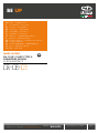 1
1
-
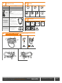 2
2
-
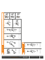 3
3
-
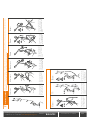 4
4
-
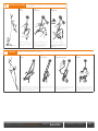 5
5
-
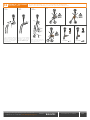 6
6
-
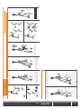 7
7
-
 8
8
-
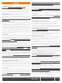 9
9
-
 10
10
-
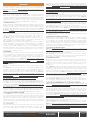 11
11
-
 12
12
-
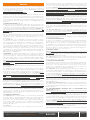 13
13
-
 14
14
-
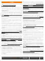 15
15
-
 16
16
-
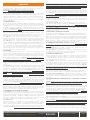 17
17
-
 18
18
-
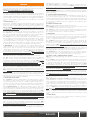 19
19
-
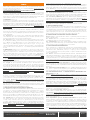 20
20
-
 21
21
-
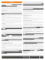 22
22
-
 23
23
-
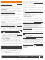 24
24
-
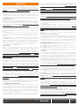 25
25
-
 26
26
-
 27
27
-
 28
28
-
 29
29


in altre lingue
- English: SKYLOTEC 2D657 User manual
- français: SKYLOTEC 2D657 Manuel utilisateur
- español: SKYLOTEC 2D657 Manual de usuario
- Deutsch: SKYLOTEC 2D657 Benutzerhandbuch
- Nederlands: SKYLOTEC 2D657 Handleiding
- português: SKYLOTEC 2D657 Manual do usuário
- dansk: SKYLOTEC 2D657 Brugermanual
- čeština: SKYLOTEC 2D657 Uživatelský manuál
- svenska: SKYLOTEC 2D657 Användarmanual
- suomi: SKYLOTEC 2D657 Ohjekirja
Documenti correlati
Altri documenti
-
Climbing Technology 2D605 Istruzioni per l'uso
-
-
-
-
Petzl VERSO Technical Notice
-
-
-
-
-