
OPERATOR'S MANUAL
BOX SCRAPERS
MAN1250
(Rev. 3/5/2018)
BSS54E, BSS60E,
BSS65E,BSS72E
BSM72E, BSM84E

Gen’l CE Euro (Rev. 3/27/2017)
2 Introduction
TO THE DEALER:
Assembly and proper installation of this product is the responsibility of the Woods
®
dealer. Read manual instructions
and safety rules. Make sure all items on the Dealer’s Pre-Delivery and Delivery Check Lists in the Operator’s Manual
are completed before releasing equipment to the owner.
PRODUCT REGISTRATION:
The end user must complete the online Product Registration form at the Woods Website. End users can register all
Woods product at WoodsEquipment.eu under Warranty
.
Failure to register the product does not diminish customer’s warranty rights.
TO THE OWNER:
Read this manual before operating your Woods equipment. The information presented will prepare you to do a better and
safer job. Keep this manual handy for ready reference. Require all operators to read this manual carefully and become
acquainted with all the adjustment and operating procedures before attempting to operate. Replacement manuals can be
obtained from your dealer. To locate your nearest dealer, check the Dealer Locater at www.WoodsEquipment.eu, or call
+32 10 301111 in Belgium.
The equipment you have purchased has been carefully engineered and manufactured to provide dependable and
satisfactory use. Like all mechanical products, it will require cleaning and upkeep. Lubricate the unit as specified.
Observe all safety information in this manual and safety decals on the equipment.
For service, your authorized Woods dealer has trained mechanics, genuine Woods service parts, and the necessary
tools and equipment to handle all your needs.
Use only genuine Woods service parts. Substitute parts will void the warranty and may not meet standards required for
safe and satisfactory operation. Record the model number and serial number of your equipment in the spaces
provided:
Model: _______________________________ Date of Purchase: _____________________
Serial Number: (see Safety Decal section for location) ____________________________________
Provide this information to your dealer to obtain correct repair parts.
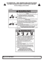
Throughout this manual, the term NOTICE is used to indicate that failure to observe can cause damage to equipment.
The terms CAUTION, WARNING and DANGER are used in conjunction with the Safety-Alert Symbol, (a triangle with
an exclamation mark), to indicate the degree of hazard for items of personal safety.

Introduction 3
MAN1250 (3/05/2018)
TABLE OF CONTENTS
INTRODUCTION. . . . . . . . . . . . . . . . . . . . . . . . . . . . . . . . . . . . . . . . . . . . . . . . . . . . . . . . . . . . . . . . . . . . . . . . . 2
SPECIFICATIONS . . . . . . . . . . . . . . . . . . . . . . . . . . . . . . . . . . . . . . . . . . . . . . . . . . . . . . . . . . . . . . . . . . . . . . . 3
GENERAL INFORMATION. . . . . . . . . . . . . . . . . . . . . . . . . . . . . . . . . . . . . . . . . . . . . . . . . . . . . . . . . . . . . . . . . 3
SAFETY RULES . . . . . . . . . . . . . . . . . . . . . . . . . . . . . . . . . . . . . . . . . . . . . . . . . . . . . . . . . . . . . . . . . . . . . . . . . 4
SAFETY DECALS. . . . . . . . . . . . . . . . . . . . . . . . . . . . . . . . . . . . . . . . . . . . . . . . . . . . . . . . . . . . . . . . . . . . . . . . 5
DECLARATION OF CONFORMITY . . . . . . . . . . . . . . . . . . . . . . . . . . . . . . . . . . . . . . . . . . . . . . . . . . . . . . . . . . 7
OPERATION. . . . . . . . . . . . . . . . . . . . . . . . . . . . . . . . . . . . . . . . . . . . . . . . . . . . . . . . . . . . . . . . . . . . . . . . . . . . 8
OWNER SERVICE . . . . . . . . . . . . . . . . . . . . . . . . . . . . . . . . . . . . . . . . . . . . . . . . . . . . . . . . . . . . . . . . . . . . . . 10
ASSEMBLY. . . . . . . . . . . . . . . . . . . . . . . . . . . . . . . . . . . . . . . . . . . . . . . . . . . . . . . . . . . . . . . . . . . . . . . . . . . . 11
DEALER CHECK LISTS . . . . . . . . . . . . . . . . . . . . . . . . . . . . . . . . . . . . . . . . . . . . . . . . . . . . . . . . . . . . . . . . . . 11
PARTS . . . . . . . . . . . . . . . . . . . . . . . . . . . . . . . . . . . . . . . . . . . . . . . . . . . . . . . . . . . . . . . . . . . . . . . . . . . . . . . 12
BOLT TORQUE CHART . . . . . . . . . . . . . . . . . . . . . . . . . . . . . . . . . . . . . . . . . . . . . . . . . . . . . . . . . . . . . . . . . . 16
BOLT SIZE CHART & ABBREVIATIONS . . . . . . . . . . . . . . . . . . . . . . . . . . . . . . . . . . . . . . . . . . . . . . . . . . . . . 17
PRODUCT WARRANTY. . . . . . . . . . . . . . . . . . . . . . . . . . . . . . . . . . . . . . . . . . . . . . . . . . . . . . . . . . . . . . . . . . 18
REPLACEMENT PARTS WARRANTY. . . . . . . . . . . . . . . . . . . . . . . . . . . . . . . . . . . . . . . . . . . . . . . . . . . . . . . 19
SPECIFICATIONS
GENERAL INFORMATION
The purpose of this manual is to assist you in operating and maintaining your
Box Scraper. Read it carefully. It furnishes information and instructions that will
help you achieve years of dependable performance.
These instructions have been compiled from extensive field experience and
engineering data. Some information may be general in nature, due to unknown
and varying operating conditions. However, through experience and these
instructions, you should be able to develop procedures suitable to your particu-
lar situation.
The illustrations and data used in this manual were current at the time of print-
ing. However, due to possible inline production changes, your machine may
vary slightly in detail. We reserve the right to redesign and change the
machines as may be necessary without notification.
Throughout this manual, references are made to right and left directions. These
are determined by standing behind the tractor facing the direction of forward
travel
.
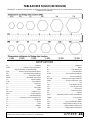
BSS54E BSS60E BSS65E BSS72E BSM72E BSM84E
Width 1.37m (54") 1.52m (60") 1.65m (65") 1.83m (72") 1.83m (72") 2.13m (84")
Height to Top Link Pin .86m (34") .86m (34") .86m (34") .86m (34") .86m (34") .86m (34")
Depth .75m (29.6") .75m (29.6") .75m (29.6") .75m (29.6") .75m (29.6") .75m (29.6")
Number of Cutting Edges 2 2 2 2 2 2
Cutting Edge Size 12.7mm x 152.4mm
(1/2" x 6")
(Reversible)
12.7mm x 152.4mm
(1/2" x 6")
(Reversible)
12.7mm x 152.4mm
(1/2" x 6")
(Reversible)
12.7mm x 152.4mm
(1/2" x 6")
(Reversible)
12.7mm x 152.4mm
(1/2" x 6")
(Reversible)
12.7mm x 152.4mm
(1/2" x 6")
(Reversible)
Approximate Weight 220.4kg (486 lbs) 233.1kg
(514 lbs)
239.5kg
(528 lbs)
249.9kg
(551 lbs)
308.4kg
(680 lbs)
340.2kg
(750 lbs)
Number of Shanks/Points 4 5 5 6 6 7
Floating Hinged Tailgate No No No No Optional Optional
Tractor HP Requirement 33.6kW
(45 hp max)
33.6kW
(45 hp max)
33.6kW
(45 hp max)
33.6kW
(45 hp max)
48.5kW
(65 hp max)
48.5kW
(65 hp max)
Tractor Hitch Class Cat 1 Cat 1 Cat 1 Cat 1 Cat 1 & 2 Cat 1 & 2
SAE Quick Hitch Yes Yes Yes Yes Yes Yes
Scarifier Depth Range 0 - 76.2mm (3") 0 - 76.2mm (3") 0 - 76.2mm (3") 0 - 76.2mm (3") 0 - 76.2mm (3") 0 - 76.2mm (3")
Heaped Capacity .27m
3
(9.7 ft
3
)
.31m
3
(10.8 ft
3
)
.33m
3
(11.7 ft
3
)
.37m
3
(13.0 ft
3
)
.37m
3
(13.0 ft
3
)
.43m
3
(15.1 ft
3
)

4 Safety
GB&HB Box Blade SR (Rev. 3/28/2005)
TRAINING
Safety instructions are important! Read all attachment and power unit
manuals; follow all safety rules and safety decal information. (Replace-
ment manuals and safety decals are available from your dealer. To locate
your nearest dealer, check the Dealer Locator at www.WoodsEquip-
ment.com, or in the United States and Canada call 1-800-319-6637.) Fail-
ure to follow instructions or safety rules can result in serious injury or
death.
If you do not understand any part of this manual and need assis-
tance, see your dealer.
Know your controls and how to stop engine and attachment quickly
in an emergency.
Operators must be instructed in and be capable of the safe operation
of the equipment, its attachments, and all controls. Do not allow anyone to
operate this equipment without proper instructions.
Never allow children or untrained persons to operate equipment.
PREPARATION
Check that all hardware is properly installed. Always tighten to
torque chart specifications unless instructed otherwise in this manual.
Always wear relatively tight and belted clothing to avoid getting
caught in moving parts. Wear sturdy, rough-soled work shoes and protec-
tive equipment for eyes, hair, hands, hearing, and head; and respirator or
filter mask where appropriate.
Make sure attachment is properly secured, adjusted, and in good
operating condition.
Power unit must be equipped with ROPS or ROPS cab and seat belt.
Keep seat belt securely fastened. Falling off power unit can result in
death from being run over or crushed. Keep foldable ROPS system in
“locked up” position at all times.
Make sure all safety decals are installed. Replace if damaged. (See
Safety Decals section for location.)
A minimum 20% of tractor and equipment weight must be on the trac-
tor front wheels when attachments are in transport position. Without this
weight, tractor could tip over, causing personal injury or death. The
weight may be attained with a loader, front wheel weights, ballast in tires
or front tractor weights. Weigh the tractor and equipment. Do not esti-
mate.
OPERATION
Do not operate or transport equipment while under the influence of
alcohol or drugs.
Always comply with all state and local lighting and marking require-
ments.
Operate only in daylight or good artificial light.
Keep bystanders away from equipment.
Keep hands, feet, hair, and clothing away from equipment while
engine is running. Stay clear of all moving parts.
Power unit must be equipped with ROPS or ROPS cab and seat belt.
Keep seat belt securely fastened. Falling off power unit can result in
death from being run over or crushed. Keep foldable ROPS system in
“locked up” position at all times.
Never allow riders on power unit or attachment.
Always sit in power unit seat when operating controls or starting
engine. Securely fasten seat belt, place transmission in neutral, engage
brake, and ensure all other controls are disengaged before starting power
unit engine.
Look down and to the rear and make sure area is clear before operat-
ing in reverse.
Use extreme care when working close to fences, ditches, other
obstructions, or on hillsides.
Do not operate or transport on steep slopes.
Do not stop, start, or change directions suddenly on slopes.
Use extreme care and reduce ground speed on slopes and rough ter-
rain.
Watch for hidden hazards on the terrain during operation.
Stop power unit and equipment immediately upon striking an
obstruction. Turn off engine, remove key, inspect, and repair any damage
before resuming operation.
Do not allow bystanders in the area when operating, attaching,
removing, assembling, or servicing equipment.
Do not allow bystanders in the area when operating, attaching,
removing, assembling, or servicing equipment.
Do not operate box scraper at speeds above 5 kpm.
MAINTENANCE
Before performing any service or maintenance, lower attachment to
ground, turn off engine, set parking brake, and remove key.
NEVER GO UNDERNEATH EQUIPMENT. Never place any part of the
body underneath equipment or between moveable parts even when the
engine has been turned off. Hydraulic system leak-down, hydraulic sys-
tem failures, mechanical failures, or movement of control levers can
cause equipment to drop or rotate unexpectedly and cause severe injury
or death.
• Service work does not require going underneath.
• Read Operator's Manual for service instructions or have service
performed by a qualified dealer.
Always wear relatively tight and belted clothing to avoid getting
caught in moving parts. Wear sturdy, rough-soled work shoes and protec-
tive equipment for eyes, hair, hands, hearing, and head; and respirator or
filter mask where appropriate.
Make sure attachment is properly secured, adjusted, and in good
operating condition.
Do not modify or alter or permit anyone else to modify or alter the
equipment or any of its components in any way.
Never perform service or maintenance with engine running.
Keep all persons away from operator control area while performing
adjustments, service, or maintenance.
Eye protection must be used when removing or installing scarifier
shank clips.
Tighten all bolts, nuts, and screws to torque chart specifications.
Check that all cotter pins are installed securely to ensure equipment is in
a safe condition before putting unit into service.
Make sure all safety decals are installed. Replace if damaged. (See
Safety Decals section for location.)
STORAGE
Block equipment securely for storage.
Keep children and bystanders away from storage area.
Lock scarifier bar in lowered position for storage.
Safety is a primary concern in the design and manufacture of our products.
Unfortunately, our efforts to provide safe equipment can be wiped out by an
operator’s single careless act.
In addition to the design and configuration of equipment, hazard control and
accident prevention are dependent upon the awareness, concern, judge-
ment, and proper training of personnel involved in the operation, transport,
maintenance, and storage of equipment.
It has been said, “The best safety device is an informed, careful operator.”
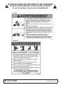
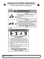
SAFETY RULES
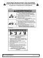
ATTENTION! BECOME ALERT! YOUR SAFETY IS INVOLVED!

Safety 5
MAN1250 (3/05/2018)
2 – 551221 – Serial Number Plate
BE CAREFUL!
Use a clean, damp cloth to clean safety decals.
Avoid spraying too close to decals when using a pressure
washer; high-pressure water can enter through very small
scratches or under edges of decals causing them to peel
or come off.
Replacement safety decals can be ordered free from your
Woods dealer. To locate your nearest dealer, check the
Dealer Locator at www.WoodsEquipment.eu,
or call +32 10 301111 in Belgium.
DP1
SAFETY & INSTRUCTIONAL DECALS
ATTENTION! BECOME ALERT! YOUR SAFETY IS INVOLVED!
Replace Immediately If Damaged!

6 Safety
MAN1250 (3/05/2018)
SAFETY & INSTRUCTIONAL DECALS
ATTENTION! BECOME ALERT! YOUR SAFETY IS INVOLVED!
Replace Immediately If Damaged!
3 – 55121
4 - 1003751

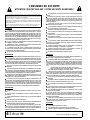
Declaration of Conformity 7
MAN1250 (3/5/2018)

8 Operation
MAN1250 (3/05/2018)
OPERATION
The operator is responsible for the safe operation of this equipment. The operator
must be properly trained. Operators should be familiar with the equipment, the
tractor, and all safety practices before starting operation. Read the safety rules
and safety decals on page 4 through page 5.
The box scrapers are designed for a wide range of applications: scarifying, scrap-
ing, leveling, grading, and backfilling.
PRE-OPERATION CHECK LIST
(OWNER'S RESPONSIBILITY)
___ Review and follow all safety rules and safety decal instructions on page 4
through page 5.
___ Check that equipment is properly and securely attached to tractor.
___ Check that all safety decals are installed and in good condition. Replace if
damaged.
___ Check that all hardware is properly installed and secured.
___ Do not allow riders.
___ Make sure tractor ROPS or ROPS CAB and seat belt are in good condi-
tion. Keep seat belt securely fastened during operation.
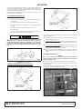
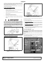
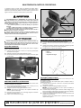
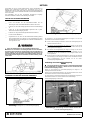
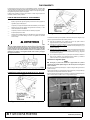
A minimum 20% of tractor and equipment weight must be on the tractor
front wheels when attachments are in transport position. Without this
weight, front tractor wheels could raise up resulting in loss of steering. The
weight may be attained with front wheel weights, ballast in tires, front trac-
tor weights or front loader. Weigh the tractor and equipment. Do not esti-
mate.
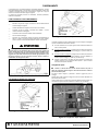
Figure 1
. Tractor Stability
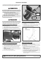
CONNECTING BOX SCRAPER TO TRACTOR
Figure 2
. Category 1, 3-Point Hitch Connection
Figure 3
. Category 2, 3-Point Hitch Connection
The box scraper is compatible with Category 1, 3-point tractors equipped with side
swing-type lower lift arms.
1.
To avoid interference with the box scraper, adjust tractor drawbar to the
shortest and highest position.
2.
For tractors with Category 1 hitch: Attach the tractor’s lower lift arms to the
scraper and secure in place with Category 1 mounting pin (1) and lynch pin
(2).
3.
For tractors with Category 2 hitch: Attach the tractor’s lower lift arms to the
scraper in the outer hitch position with adapter sleeves (3) assembled over
mounting pins (1) and secured with lynch pins (2).
4.
Attach the tractor's top link to the top of the box scraper's mast and secure
with the heavy-duty top link pin and retaining pin supplied with the tractor
top link.
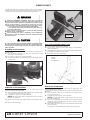
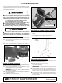
Quick Hitch Connection
NOTICE
■
The 3/4" bolt and sleeve in the lower hole provide the attachment
point for a Category 1 quick coupler. Do not remove this bolt and sleeve
when operating the scraper.
For Category 1 quick hitch application, place hitch sleeves over mounting pin.
Align quick hitch with 3-point mount pins and top spacer sleeve between the right
and left mast plates.
The top quick hitch hook will seat into spacer sleeve. This sleeve does not inter-
fere when unit is used with a standard 3-point hitch.
Figure 4. Top Quick Hitch Hook Connection
WARNING

Operation 9
MAN1250 (3/05/2018)
ADJUSTING TOP LINK
The box scraper is leveled by adjusting the length of the tractor's top link.
●
Shortening the top link will deepen the scarifier tooth penetration.
●
Lengthening the top link will provide better scraping and leveling action.
Experience will allow the operator to determine the best setting for the application
being done.
NOTICE
■
This unit is intended to move ground materials such as dirt, sand,
gravel, etc. Unintended use may damage the box scraper.
SCARIFYING
1.
Place the scarifier shanks in position with the points facing toward the
tractor.
2.
Lock into position with the lock pins provided. The lower shank position
provides the greatest ground penetration.
3.
Lower the box scraper and drive the tractor ahead to begin the scarifying
operation.
4.
Adjust the depth of the scarifier by tilting the unit with the tractor top link.
Shortening the top link will provide deeper and more aggressive operation.
SCRAPING
1.
Raise or remove the scarifier shanks. Lower the box scraper and drive
forward to move material.
2.
Adjust the depth of the scraper by tilting the unit with the tractor top link.
Shortening the top link when scraping will transfer more weight on the front
of the scraper and will raise the cutting scraper to provide a more shallow
cut.
NOTE:
When the top link is adjusted properly, the bowl of the scraper
should fill easily and material can be pulled to a desired location.
3.
To change the level of the scraper, shorten or lengthen the tractor lift arm tilt
link to provide the correct slope.
4.
Spread material by gradually raising the box scraper as the tractor moves
forward.
NOTE:
Top link adjustment for loose or previously scarified material will
differ from adjustment for hard or compacted material.
BACKFILLING
1.
Raise or remove scarifier shanks.
2.
Lower the scraper to the ground and back up into the fill material.
3.
Shorten the top link to raise the cutting scraper and control how much the
scraper digs in.
LEVELING
1.
Raise or remove scarifier shanks.
2.
Shorten the top link so the cutting edge clears the ground.
3.
Drive forward with the box scraper in this position and loose material will be
leveled.
CLEANING
After Each Use
●
Remove large debris such as clumps of dirt, grass, crop residue, etc. from
machine.
●
Inspect machine and replace worn or damaged parts.
●
Replace any safety decals that are missing or not readable.
Periodically or Before Extended Storage
●
Clean large debris such as clumps of dirt, grass, crop residue, etc. from
machine.
●
Remove the remainder using a low-pressure water spray.
1.
Be careful when spraying near scratched or torn safety decals or near
edges of decals as water spray can peel decal off surface.
2.
Be careful when spraying near chipped or scratched paint as water
spray can lift paint.
3.
If a pressure washer is used, follow the advice of the pressure washer
manufacturer.
●
Inspect machine and replace worn or damaged parts.
●
Sand down scratches and the edges of areas of missing paint and coat
with spray paint of matching color (purchase from your dealer).
●
Replace any safety decals that are missing or not readable (supplied free
by your dealer). See Safety Decals section for location drawing.
STORAGE
Block equipment securely for storage.
Keep children and bystanders away from storage area.
To help prevent injury caused by a falling implement, always detach on
a hard level surface.
Do not climb or lean on stored equipment.

10 Owner Service
MAN1250 (3/05/2018)
OWNER SERVICE
The information in this section is written for operators who possess basic mechan-
ical skills. If you need help, your dealer has trained service technicians available.
For your protection, read and follow the safety information in this manual.
NEVER GO UNDERNEATH EQUIPMENT. Never place any part of the
body underneath equipment or between moveable parts even when the
engine has been turned off. Hydraulic system leak-down, hydraulic system
failures, mechanical failures, or movement of control levers can cause
equipment to drop or rotate unexpectedly and cause severe injury or death.
• Service work does not require going underneath implement.
• Read Operator's Manual for service instructions or have service per-
formed by a qualified dealer.
Keep all persons away from operator control area while performing
adjustments, service, or maintenance.
Before performing any service or maintenance, lower equipment to
ground or block securely, turn off engine, remove key, and disconnect drive-
line from tractor PTO.
Always wear relatively tight and belted clothing to avoid getting caught
in moving parts. Wear sturdy, rough-soled work shoes and protective equip-
ment for eyes, hair, hands, hearing, and head; and respirator or filter mask
where appropriate.
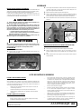
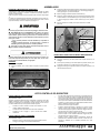
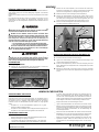
BLOCKING UP BOX SCRAPER
NOTE: To service the box scraper when attached to the tractor, it must be blocked
up off the ground.
1.
Place two 150mm x 150mm (6" x 6") blocks under each side frame of the
box scraper as shown in Figure 5.
2.
Lower the box scraper to rest securely on the blocks.
3.
Do not block the machine any higher than needed for removing the shanks
or cutting edge.
Figure 5.
Box Scraper Blocked Up
REMOVING SCARIFIER SHANKS
Scarifier shanks have three operating positions in the scraper. They may be
removed if scarifying action is not needed.
1.
Block up machine by placing two 150mm x 150mm (6" x 6") blocks under
each side-frame of the box scraper (see Figure 5).
2.
Lower the box scraper to rest securely on the blocks.
NOTE:
Do not block the machine any higher than necessary to remove
the shanks or cutting edge.
3.
Remove safety pin and lock pin. Adjust scarifier to desired position, Figure
6.
4.
Replace safety and lock pins.
Figure 6
. Scarifier Shank Adjustment
REPLACING SCARIFIER SHANK TOOTH
1.
Remove scarifier shank from the scarifier bar.
2.
Refer to Figure 7. Remove the worn tooth by driving a chisel between the
shank (1) and tooth (2).
3.
Install replacement tooth and use a punch (3) to bend the locking tab (4) into
the retaining hole on both sides of the shank.
4.
Reinstall the shank in the scarifier holder.
Figure 7
. Scarifier Point Replacement
REPLACING CUTTING EDGE
All box scraper models use two 12.7mm x 152 mm (1/2" x 6") cutting edges. They
are interchangeable and reversible.
To service the box scraper when attached to the tractor, it must be blocked up off
the ground.
1.
Place two 150mm x 150mm (6" x 6") blocks under each side-frame of the
box scraper (see Figure 5).
2.
Lower the box scraper to rest securely on the blocks.
NOTE:
Do not block the machine any higher than necessary to remove
the shanks or cutting edge.
3.
Refer to parts drawing, page 14. Remove the lock nuts (16) and plow bolts
(18) from box scraper. Turn cutting edge over and use new edge, or replace
it if both edges have been used.
4.
Attach cutting edge to box scraper and secure with plow bolts and hex nuts
previously removed.
Torque plow bolts to specifications given in Bolt Torque Chart, page 16.
WARNING
CAUTIONCAUTION
Lock Pin
Safety Pin
DP5
1. Shank
2. Tooth
3. Punch
4. Locking Tab

Assembly 11
MAN1250 (3/05/2018)
ASSEMBLY
DEALER SET-UP INSTRUCTIONS
Assembly of this Box Scraper is the responsibility of the WOODS dealer. It
should be delivered to the owner completely assembled and adjusted for nor-
mal conditions.
Complete the Check Lists on page 15 before delivering the attachment to the
customer.
The Box Scraper is shipped partially assembled. Assembly will be easier if
components are aligned and loosely assembled before tightening hardware.
Recommended torque values for hardware are located on page 16.
Before performing any service or maintenance, lower attachment to
ground, turn off engine, set parking brake, and remove key.
NEVER GO UNDERNEATH EQUIPMENT. Never place any part of the
body underneath equipment or between moveable parts even when the
engine has been turned off. Hydraulic system leak-down, hydraulic sys-
tem failures, mechanical failures, or movement of control levers can
cause equipment to drop or rotate unexpectedly and cause severe injury
or death.
• Service work does not require going underneath implement.
• Read Operator's Manual for service instructions or have service
performed by a qualified dealer.
Keep all persons away from operator control area while performing
adjustments, service, or maintenance.
Always wear relatively tight and belted clothing to avoid getting
caught in moving parts. Wear sturdy, rough-soled work shoes and protec-
tive equipment for eyes, hair, hands, hearing, and head; and respirator or
filter mask where appropriate.
BOX SCRAPER
Assemble Box Scraper
1.
Remove the banding, straps and lag bolts that holds the box scrapers
and mast plates to the pallet.
Figure 8.
Shipping Configuration - Box Scraper
2.
Place right mast plate (2) to the inside of right cross support bar and
secure into position using three hex flange screws (19) and flange lock
nuts (17). See page 14 for part diagram.
3.
Repeat step to install left mast plate (3).
4.
Place spacer sleeve (23) between mast plates lower front hole and
secure into position using cap screws (22) two (one on either side) flat
washers (21) and lock nuts (20). Install second sleeve (23) in lower rear
hole.
5.
Tighten 5/8" hardware to 230Nm (170 lbs-ft) and 3/4" hardware to 403Nm
(297 lbs-ft).
Figure 9
. Spacer Sleeve Installation
INSTALL TAILGATE ON BSM MODELS (OPTIONAL)
1.
Remove rear cutting edge from box scraper.
2.
Place tailgate (5) against rear of box scraper and align mounting holes.
3.
Insert tailgate pins (4) through holes on box scraper and tailgate. Secure
tailgate pin into position using flat washers (24) and spring pins (15).
4.
Attach cutting edge against tailgate and align holes and secure into
position using hardware previously removed.
DEALER CHECK LISTS
PRE-DELIVERY CHECK LIST
(Dealer's Responsibility)
Inspect the equipment thoroughly after assembly to be certain it is set up prop-
erly before delivering it to the customer. The following check list is a reminder
of points to inspect. Check off each item if it is found satisfactory or after proper
adjustment is made.
___ Check that all safety decals are installed and in good condition.
Replace if damaged.
___ Check all bolts to be sure they are properly torqued.
___ Check that all cotter pins and safety pins are properly installed.
DELIVERY CHECK LIST
(Dealer's Responsibility)
___ Show customer the safe, proper procedures to be used when
mounting, dismounting, and storing equipment.
___ For mounted units, add wheel weights, ballast in front tires, and/or
front tractor weight to enhance front end stability. A minimum 20%
of tractor and equipment gross weight must be on front tractor
wheels. When adding weight to attain 20% of tractor and equip-
ment weight on front tractor wheels, you must not exceed the
ROPS weight certification. Weigh the tractor and equipment. Do
not estimate!
___ Show customer how to make adjustments.
___ Present Operator's Manual and request that customer and all oper-
ators read it before operating equipment. Point out the manual
safety rules, explain their meanings and emphasize the increased
safety hazards that exist when safety rules are not followed.
___ Point out the safety decals. Explain their meaning and the need to
keep them in place and in good condition. Emphasize the
increased safety hazards when instructions are not followed.
___ Explain to customer the potential crushing hazards of going under-
neath raised equipment. Instruct customer that service work does
not require going underneath unit and never to do so.
WARNING
CAUTIONCAUTION
23
21
20
3
2

12 Assembly
MAN1250 (3/05/2018)
NOTES

Parts 13
MAN1250 (3/05/2018)
Box Scrapers
PARTS INDEX
BSS/BSM BOX SCRAPER. . . . . . . . . . . . . . . . . . . . . . . . . . . . . . . . . . 12
BSS/BSM BOX SCRAPER PARTS LIST . . . . . . . . . . . . . . . . . . . . . . . 13

14 Parts
MAN1250 (3/05/2018)
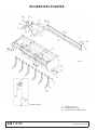
BSS/BSM BOX SCRAPER
9. - Safety Decal Set
10. - Complete Decal Set
11. - Quick Hitch Cat 1 Bushing Kit

Parts 15
MAN1250 (3/05/2018)
BSS/BSM BOX SCRAPER PARTS LIST
REF BSS BSM QTY DESCRIPTION
1
SU105
2 Drawbar pin w/lynch pin
1
HBL233
2 Cat 2 Drawbar pin
2
1029092RP
1 Mast plate - right
2
1029102RP
1 Mast plate - right
3
1029053
1 Mast plate -left
3
1029101
1 Mast plate -left
4
1029106RP
3 Tailgate pin optional
5
102908672RP
1 Tailgate (BSM72)
optional
5
102908684RP
1 Tailgate (BSM84)
optional
6
1029062
2 Cutting edge (BSS54)
6
32280
2 Cutting edge (BSS60)
6
55316
2 Cutting edge (BSS65)
6
25258 25258
2 Cutting edge
(BSS72/BSM72)
6
46440
2 Cutting edge (BSM84)
7
1005338
4 Pin w/Clip (BSS54)
7
1005338
5 Pin w/Clip (BSS65)
7
1005338 1005338
6 Pin w/Clip
(BSS72/BSM72)
7
1005338
7 Pin w/Clip (BSM84)
REF BSS BSM QTY DESCRIPTION
8 1004635 4 Scarifier & tip (BSS54)
8 1004635 5 Scarifier & tip
(BSS60/BSS65)
8 1004635 6 Scarifier & tip (BSS72)
8 1035770 7 Scarifier & tip, Heavy
Duty (BSM72/BSM84)
8a 1004636 A/R Scarifier tip (replaceable)
8a 1035769 A/R Scarifier tip, Heavy Duty
9 1003898 1003898 Safety decal set XB
10 1029113 1029113 Complete decal set
11 1023725 1023725 2 Quick Hitch Bushing Kit
(Cat - 1)
12 1026530 1026530 1 Manual tube (optional)
15 4115 2 Spring pin, 3/16 x 1-1/8
16 6239 6239 * 5/8 NC Lock nut
17 19025 19025 * 5/8 NC flange lock nut
18 25265 25265 * 5/8 NC x 1-1/2 Plow bolt
19 19024 19024 * 5/8 NC x 1-3/4 HFS GR5
20 2371 2371 * 3/4 NC Lock nut
21 2864 2864 * 3/4 Flat washer
22 31207 31207 * 3/4 NC x 4 HHCS GR5
23 1002018 1002018 2 Sleeve, .81 x 1.25 x 2.12
24 W28539 2* 7/8 Flat washer
25 27542 4 7/16 Lynch pin
26 56598 2 Sleeve, Cat 2 adapter
HFS Hex Flange Screw
HHCS Hex Head Cap Screw
A/R As Required
NS Not Shown
* Standard hardware,
obtain locally

Appendix 16
Bolt Torque & Size Charts (Rev. 3/28/2007)
BOLT TORQUE CHART
Always tighten hardware to these values unless a different torque value or tightening procedure is listed for a specific
application.
Fasteners must always be replaced with the same grade as specified in the manual parts list.
Always use the proper tool for tightening hardware: SAE for SAE hardware and Metric for metric hardware.
Make sure fastener threads are clean and you start thread engagement properly.
All torque values are given to specifications used on hardware defined by SAE J1701 MAR 99 & J1701M JUL 96.
Diameter
(Inches)
Wrench
Size
MARKING ON HEAD
SAE 2 SAE 5 SAE 8
lbs-ft N-m lbs-ft N-m lbs-ft N-m
1/4" 7/16" 6 8 10 13 14 18
5/16"1/2"121719262737
3/8"9/16"233135474967
7/16"5/8"3648557578106
1/2" 3/4" 55 75 85 115 120 163
9/16" 13/16" 78 106 121 164 171 232
5/8" 15/16" 110 149 170 230 240 325
3/4" 1-1/8" 192 261 297 403 420 569
7/8" 1-5/16" 306 416 474 642 669 907
1" 1-1/2" 467 634 722 979 1020 1383
Diameter &
Thread Pitch
(Millimeters)
Wrench
Size
Coarse Thread Fine Thread
Diameter &
Thread Pitch
(Millimeters)
Marking on Head Marking on Head
Metric 8.8 Metric 10.9 Metric 8.8 Metric 10.9
N-m lbs-ft N-m lbs-ft N-m lbs-ft N-m lbs-ft
6 x 1.0 10 mm 8 6 11 8 8 6 11 8 6 x 1.0
8 x 1.25 13 mm 20 15 27 20 21 16 29 22 8 x 1.0
10 x 1.5 16 mm 39 29 54 40 41 30 57 42 10 x 1.25
12 x 1.75 18 mm 68 50 94 70 75 55 103 76 12 x 1.25
14 x 2.0 21 mm 109 80 151 111 118 87 163 120 14 x 1.5
16 x 2.0 24 mm 169 125 234 173 181 133 250 184 16 x 1.5
18 x 2.5 27 mm 234 172 323 239 263 194 363 268 18 x 1.5
20 x 2.5 30 mm 330 244 457 337 367 270 507 374 20 x 1.5
22 x 2.5 34 mm 451 332 623 460 495 365 684 505 22 x 1.5
24 x 3.0 36 mm 571 421 790 583 623 459 861 635 24 x 2.0
30 x 3.0 46 mm 1175 867 1626 1199 1258 928 1740 1283 30 x 2.0
A
SAE SERIES
TORQUE
CHART
SAE Bolt Head
Identification
SAE Grade 2
(No Dashes)
SAE Grade 5
(3 Radial Dashes)
SAE Grade 8
(6 Radial Dashes)
A
METRIC SERIES
TORQUE
CHART
Metric Bolt Head
Identification
8.8
Metric
Grade 10.9
10.9
Metric
Grade 8.8
A
A
A
Typical Washer
Installations
Lock Washer
Flat Washer
8/9/00
:1;1

Bolt Torque & Size Charts (Rev. 3/28/2007)
17 Appendix
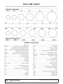
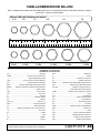
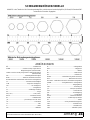
BOLT SIZE CHART
NOTE: Chart shows bolt thread sizes and corresponding head (wrench) sizes for standard SAE and metric bolts.
ABBREVIATIONS
AG...............................................................Agriculture
ASABE....................American Society of Agricultural &
Biological Engineers (formerly ASAE)
ASAE .......American Society of Agricultural Engineers
ATF...............................Automatic Transmission Fluid
BSPP ............................British Standard Pipe Parallel
BSPTM................British Standard Pipe Tapered Male
CV....................................................Constant Velocity
CCW ..............................................Counter-Clockwise
CW...............................................................Clockwise
F.......................................................................Female
FT...............................................................Full Thread
GA.....................................................................Gauge
GR (5, etc.) ...........................................Grade (5, etc.)
HHCS........................................ Hex Head Cap Screw
HT...........................................................Heat-Treated
JIC..............................Joint Industry Council 37° Flare
LH ................................................................ Left Hand
LT...........................................................................Left
m.........................................................................Meter
mm................................................................Millimeter
M..........................................................................Male
MPa.........................................................Mega Pascal
N......................................................................Newton
NC ......................................................National Coarse
NF...........................................................National Fine
NPSM.................... National Pipe Straight Mechanical
NPT ..........................................National Pipe Tapered
NPT SWF ........National Pipe Tapered Swivel Female
ORBM...........................................O-Ring Boss - Male
P.......................................................................... Pitch
PBY ......................................................Power-Beyond
psi..........................................Pounds per Square Inch
PTO.................................................... Power Take Off
QD................................................... Quick Disconnect
RH ............................................................. Right Hand
ROPS ...........................Roll-Over Protective Structure
RPM........................................Revolutions Per Minute
RT........................................................................Right
SAE ......................... Society of Automotive Engineers
UNC......................................................Unified Coarse
UNF..........................................................Unified Fine
UNS..................................................... Unified Special
5/16 3/8 1/2 5/8 3/4 7/8
SAE Bolt Thread Sizes
MM 25 50 75 100 125 150 175
IN 1 7
Metric Bolt Thread Sizes
8MM 18MM14MM12MM10MM 16MM
2
34 5 6

F-3079 (3/15/2018)
WOODS
®|
A Blount International Brand
2606 South Illinois Route 2
Post Office Box 1000
Oregon, Illinois 61061 USA
800-319-6637 tel
800-399-6637 fax
woodsequipment.com
BLOUNT EUROPE SA
Rue Emile Francqui 5
1435 MONT-SANT-GUIBERT
Belgium
+32 10 301111 tel
woodsequipment.eu
WARRANTY
All Models Except Mow’n Machine
TM
Zero-Turn Mowers
Please Enter Information Below and Save for Future Reference.
Date Purchased: ____________________________ From (Dealer): __________________________________________
Model Number: ____________________________ Serial Number: __________________________________________
Woods Equipment Company (“WOODS”) warrants this product to be free from defect in material and workmanship. Except as otherwise set forth
below, the duration of this Warranty shall be for TWELVE (12) MONTHS COMMENCING ON THE DATE OF DELIVERY OF THE
PRODUCT TO THE ORIGINAL PURCHASER.
All current model backhoes, loaders and mounts (except 3-pt. SAF-T-LOK
mounts) are warranted for two (2) years from the date of delivery to
the original purchaser. The limited warranty covers any defects in the material and/or workmanship. Following the proper, recommended
installation by an authorized Woods Dealer and normal use of a Woods mounting and backhoe or loader, if a tractor incurs damage resulting from
the attachment, Woods will cover the existing tractor warranty in the event the manufacturer voids its tractor warranty because of the attachment.
Warranty does not cover any misuse or abusive conditions that could cause premature wear or damage to attachment or tractor.
The warranty periods for specific parts or conditions are listed below:
Under no circumstances will this Warranty apply in the event that the product, in the good faith opinion of WOODS, has been subjected to
improper operation, improper maintenance, misuse, or an accident. This Warranty does not apply in the event that the product has been materially
modified or repaired by someone other than WOODS, a WOODS authorized dealer or distributor, and/or a WOODS authorized service center.
This Warranty does not cover normal wear or tear, or normal maintenance items. This Warranty also does not cover repairs made with parts other
than those obtainable through WOODS.
This Warranty is extended solely to the original purchaser of the product. Should the original purchaser sell or otherwise transfer this product to a
third party, this Warranty does not transfer to the third party purchaser in any way. There are no third party beneficiaries of this Warranty.
WOODS makes no warranty, express or implied, with respect to engines, batteries, tires or other parts or accessories not manufactured by
WOODS. Warranties for these items, if any, are provided separately by their respective manufacturers.
WOODS’ obligation under this Warranty is limited to, at WOODS’ option, the repair or replacement, free of charge, of the product if WOODS, in
its sole discretion, deems it to be defective or in noncompliance with this Warranty. The product must be returned to WOODS with proof of
purchase within thirty (30) days after such defect or noncompliance is discovered or should have been discovered, routed through the
dealer and distributor from whom the purchase was made, transportation charges prepaid. WOODS shall complete such repair or
replacement within a reasonable time after WOODS receives the product. THERE ARE NO OTHER REMEDIES UNDER THIS WARRANTY.
THE REMEDY OF REPAIR OR REPLACEMENT IS THE SOLE AND EXCLUSIVE REMEDY UNDER THIS WARRANTY.
THERE ARE NO WARRANTIES WHICH EXTEND BEYOND THE DESCRIPTION ON THE FACE OF THIS WARRANTY. WOODS
MAKES NO OTHER WARRANTY, EXPRESS OR IMPLIED, AND WOODS SPECIFICALLY DISCLAIMS ANY IMPLIED WARRANTY
OF MERCHANTABILITY AND/OR ANY IMPLIED WARRANTY OF FITNESS FOR A PARTICULAR PURPOSE.
WOODS shall not be liable for any incidental or consequential losses, damages or expenses, arising directly or indirectly from the
product, whether such claim is based upon breach of contract, breach of warranty, negligence, strict liability in tort or any other legal
theory. Without limiting the generality of the foregoing, Woods specifically disclaims any damages relating to (i) lost profits, business, revenues
or goodwill; (ii) loss of crops; (iii) loss because of delay in harvesting; (iv) any expense or loss incurred for labor, supplies, substitute machinery or
rental; or (v) any other type of damage to property or economic loss.
This Warranty is subject to any existing conditions of supply which may directly affect WOODS’ ability to obtain materials or manufacture
replacement parts.
No agent, representative, dealer, distributor, serviceperson, salesperson, or employee of any company, including without limitation, WOODS, its
authorized dealers, distributors, and service centers, is authorized to alter, modify, or enlarge this Warranty. Answers to any questions regarding
warranty service and locations may be obtained by
Part or
Condition
Warranted
Model Number
Duration (from date of
delivery to the original
purchaser)
All units invoiced after 4/30/2012
Gearbox
components
BB48X, BB60X, BB72X, BB84X, BB600X, BB720X, BB840X, BB6000X, BB7200X, BB8400X,
DS12.50, TS14.60, DS1440, TS1680, DS8.30, DS10.40, DS8.50, DSO8.50, DS10.50, DSO10.50,
DBH5.30, DBH6.30
6 years
BW12, BW15, BW126X, BW180X, BW126XHD, BW180XHD, BW1260X, BW1800X
BW10.50, BW10.50Q, BW15.50, BW15.50Q, BW15.60, BW15.60Q, BW10.60, BW10.60Q
BW240X, BW240XHD, BW1620X, BW2400X
RD990X, PRD6000, PRD7200, PRD8400, S15CD, S20CD, S22CD, S25CD, S27CD, S30CD, TC/
R74, TC/R68, TC/R60, TBW144, TBW180, TBW204, TSG50, S12ED, S15ED, S18ED, S20ED,
TPD25, TPD35, TPD65, TPD95
RDC54, RD60, RD72, TBW150C, TS/R60, TS/R52, TS/R44, RC3.5, RC4, RC5, RC6
3 years (1 year if used in rental or
commercial applications)
Blade
spindles
RD990X, PRD6000, PRD7200, PRD8400, TBW144, TBW180, TBW204 3 years

F-8494 (3/15/2018)
©2017 Woods Equipment Company. All rights reserved. Woods
®
and the Woods logo are trademarks of Woods Equipment Company. All other
trademarks, trade names, or service marks not owned by Woods Equipment Company that appear in this manual are the property of their respective
companies or mark holders. Specifications subject to change without notice.
WOODS
®|
A Blount International Brand
2606 South Illinois Route 2
Post Office Box 1000
Oregon, Illinois 61061 USA
800-319-6637 tel
800-399-6637 fax
woodsequipment.com
BLOUNT EUROPE SA
Rue Emile Francqui 5
1435 MONT-SANT-GUIBERT
Belgium
+32 10 301111 tel
woodsequipment.eu
WARRANTY
(Replacement Parts For All Models Except Mow’n Machine
TM
Zero-Turn Mowers and Woods Boundary
TM
Utility Vehicles)
Woods Equipment Company (“WOODS”) warrants this product to be free from defect in material and
workmanship for a period of ninety (90) days from the date of delivery of the product to the original purchaser
with the exception of V-belts, which will be free of defect in material and workmanship for a period of 12 months.
Under no circumstances will this Warranty apply in the event that the product, in the good faith opinion of
WOODS, has been subjected to improper operation, improper maintenance, misuse, or an accident. This Warranty
does not cover normal wear or tear, or normal maintenance items.
This Warranty is extended solely to the original purchaser of the product. Should the original purchaser sell or
otherwise transfer this product to a third party, this Warranty does not transfer to the third party purchaser in any
way. There are no third party beneficiaries of this Warranty.
WOODS’ obligation under this Warranty is limited to, at WOODS’ option, the repair or replacement, free of
charge, of the product if WOODS, in its sole discretion, deems it to be defective or in noncompliance with this
Warranty. The product must be returned to WOODS with proof of purchase within thirty (30) days after
such defect or noncompliance is discovered or should have been discovered, routed through the dealer and
distributor from whom the purchase was made, transportation charges prepaid. WOODS shall complete
such repair or replacement within a reasonable time after WOODS receives the product. THERE ARE NO
OTHER REMEDIES UNDER THIS WARRANTY. THE REMEDY OF REPAIR OR REPLACEMENT IS THE
SOLE AND EXCLUSIVE REMEDY UNDER THIS WARRANTY.
THERE ARE NO WARRANTIES WHICH EXTEND BEYOND THE DESCRIPTION ON THE FACE OF THIS
WARRANTY. WOODS MAKES NO OTHER WARRANTY, EXPRESS OR IMPLIED, AND WOODS
SPECIFICALLY DISCLAIMS ANY IMPLIED WARRANTY OF MERCHANTABILITY AND/OR ANY
IMPLIED WARRANTY OF FITNESS FOR A PARTICULAR PURPOSE.
WOODS shall not be liable for any incidental or consequential losses, damages or expenses, arising directly
or indirectly from the product, whether such claim is based upon breach of contract, breach of warranty,
negligence, strict liability in tort or any other legal theory. Without limiting the generality of the foregoing,
Woods specifically disclaims any damages relating to (i) lost profits, business, revenues or goodwill; (ii) loss of
crops; (iii) loss because of delay in harvesting; (iv) any expense or loss incurred for labor, supplies, substitute
machinery or rental; or (v) any other type of damage to property or economic loss.
This Warranty is subject to any existing conditions of supply which may directly affect WOODS’ ability to obtain
materials or manufacture replacement parts.
No agent, representative, dealer, distributor, service person, salesperson, or employee of any company, including
without limitation, WOODS, its authorized dealers, distributors, and service centers, is authorized to alter, modify,
or enlarge this Warranty.
Answers to any questions regarding warranty service and locations may be obtained by contacting:

BOÎTES NIVELEUSES
MAN1250
(Rév. 05/03/2018)
BSS54E, BSS60E,
BSS65E, BSS72E,
BSM72E, BSM84E
La pagina sta caricando ...
La pagina sta caricando ...
La pagina sta caricando ...
La pagina sta caricando ...
La pagina sta caricando ...
La pagina sta caricando ...
La pagina sta caricando ...
La pagina sta caricando ...
La pagina sta caricando ...
La pagina sta caricando ...
La pagina sta caricando ...
La pagina sta caricando ...
La pagina sta caricando ...
La pagina sta caricando ...
La pagina sta caricando ...
La pagina sta caricando ...
La pagina sta caricando ...
La pagina sta caricando ...
La pagina sta caricando ...
La pagina sta caricando ...
La pagina sta caricando ...
La pagina sta caricando ...
La pagina sta caricando ...
La pagina sta caricando ...
La pagina sta caricando ...
La pagina sta caricando ...
La pagina sta caricando ...
La pagina sta caricando ...
La pagina sta caricando ...
La pagina sta caricando ...
La pagina sta caricando ...
La pagina sta caricando ...
La pagina sta caricando ...
La pagina sta caricando ...
La pagina sta caricando ...
La pagina sta caricando ...
La pagina sta caricando ...
La pagina sta caricando ...
La pagina sta caricando ...
La pagina sta caricando ...
La pagina sta caricando ...
La pagina sta caricando ...
La pagina sta caricando ...
La pagina sta caricando ...
La pagina sta caricando ...
La pagina sta caricando ...
La pagina sta caricando ...
La pagina sta caricando ...
La pagina sta caricando ...
La pagina sta caricando ...
La pagina sta caricando ...
La pagina sta caricando ...
La pagina sta caricando ...
La pagina sta caricando ...
La pagina sta caricando ...
La pagina sta caricando ...
La pagina sta caricando ...
La pagina sta caricando ...
La pagina sta caricando ...
La pagina sta caricando ...
La pagina sta caricando ...
La pagina sta caricando ...
La pagina sta caricando ...
-
 1
1
-
 2
2
-
 3
3
-
 4
4
-
 5
5
-
 6
6
-
 7
7
-
 8
8
-
 9
9
-
 10
10
-
 11
11
-
 12
12
-
 13
13
-
 14
14
-
 15
15
-
 16
16
-
 17
17
-
 18
18
-
 19
19
-
 20
20
-
 21
21
-
 22
22
-
 23
23
-
 24
24
-
 25
25
-
 26
26
-
 27
27
-
 28
28
-
 29
29
-
 30
30
-
 31
31
-
 32
32
-
 33
33
-
 34
34
-
 35
35
-
 36
36
-
 37
37
-
 38
38
-
 39
39
-
 40
40
-
 41
41
-
 42
42
-
 43
43
-
 44
44
-
 45
45
-
 46
46
-
 47
47
-
 48
48
-
 49
49
-
 50
50
-
 51
51
-
 52
52
-
 53
53
-
 54
54
-
 55
55
-
 56
56
-
 57
57
-
 58
58
-
 59
59
-
 60
60
-
 61
61
-
 62
62
-
 63
63
-
 64
64
-
 65
65
-
 66
66
-
 67
67
-
 68
68
-
 69
69
-
 70
70
-
 71
71
-
 72
72
-
 73
73
-
 74
74
-
 75
75
-
 76
76
-
 77
77
-
 78
78
-
 79
79
-
 80
80
-
 81
81
-
 82
82
-
 83
83


Woods BSS60E Manuale utente
- Tipo
- Manuale utente
in altre lingue
- English: Woods BSS60E User manual
- français: Woods BSS60E Manuel utilisateur
- español: Woods BSS60E Manual de usuario
- Deutsch: Woods BSS60E Benutzerhandbuch
Documenti correlati
Altri documenti
-
Pottinger SILOPROFI 2 Istruzioni per l'uso
-
3M DBI-SALA® Lad-Saf™ X3 Detachable Cable Sleeve 6160054, 9.5MM Istruzioni per l'uso
-
Simplicity ATTACHMENT, 885634 ADAPTER FOR SNOWTHROWER & HITCH Manuale utente
-
 Jacobsen 88005, 88007 Manuale del proprietario
-
-
 Gravely Promaster 260Z Owner's And Operator's Manual
-
-
-
Toro 210-H Tractor Manuale utente
-
Ransomes 67042 Manuale del proprietario

