Quantum QC 310 Manuale utente
- Categoria
- Amplificatore per strumenti musicali
- Tipo
- Manuale utente


IMPORTANT SAFETY INSTRUCTIONS
BEFORE CONNECTING, READ INSTRUCTIONS
• Read all of these instructions!
• Save these instructions for later use!
• Follow all warnings and instructions marked on the product!
• Do not use this product near water, i.e. bathtub, sink, swimming pool, wet basement,
etc.
• Do not place this product on an unstable cart, stand or table. The product may fall,
causing serious damage to the product or to persons!
• Slots and openings in the cabinet and the back or bottom are provided for ventilati-
on; to ensure reliable operation of the product and to protect it from overheating,
these openings must not be blocked or covered. This product should not be placed
in a built-in installation unless proper ventilation is provided.
• This product should not be placed near a source of heat such as a stove, radiator, or
another heat producing amplifier.
• Use only the supplied power supply or power cord. If you are not sure of the type of
power available, consult your dealer or local power company.
• Do not allow anything to rest on the power cord. Do not locate this product where
persons will walk on the cord.
• Never break off the ground pin on the power supply cord.
• Power supply cords should always be handled carefully. Periodically check cords for
cuts or sign of stress, especially at the plug and the point where the cord exits the
unit.
• The power supply cord should be unplugged when the unit is to be unused for long
periods of time.
• If this product is to be mounted in an equipment rack, rear support should be provided.
• This product should be used only with a cart or stand that is recommended by
Hughes & Kettner.
• Never push objects of any kind into this product through cabinet slots as they may
touch dangerous voltage points or short out parts that could result in risk of fire or
electric shock. Never spill liquid of any kind on the product.
• Do not attempt to service this product yourself, as opening or removing covers may
expose you to dangerous voltage points or other risks. Refer all servicing to qualified
service personnel.
• Unplug this product from the wall outlet and refer servicing to qualified service per-
sonnel under the following conditions:
• When the power cord or plug is damaged or frayed.
• If liquid has been spilled into the product.
• If the product has been exposed to rain or water.
• If the product does not operate normally when the operating instructions are followed.
• If the product has been dropped or the cabinet has been damaged.
• If the product exhibits a distinct change in performance, indicating a need of service!
• Adjust only these controls that are covered by the operating instructions since impro-
per adjustment of other controls may result in damage and will often require exten-
sive work by a qualified technician to restore the product to normal operation.
• Exposure to extremely high noise levels may cause a permanent hearing loss.
• Individuals vary considerably in susceptibility to noise induced hearing loss, but near-
ly everyone will lose some hearing if exposed to sufficiently intense noise for a suffi-
cient time. The U.S. Government´s Occupational Safety and Health Administration
(OSHA) has specified the following permissible noise level exposures:
Duration Per Day In Hours Sound LeveldBA, Slow Response
890
692
495
397
2100
11/2102
1105
1/2110
1/4 or less 115
• According to OSHA, any exposure in excess of the above permissible limits could
result in some hearing loss.
• Ear plug protectors in the ear canals or over the ears must be worn when operating
this amplification system in order to prevent a permanent hearing loss if exposure is
in excess of the limits as set forth above. To ensure against potentially dangerous
exposure to high sound pressure levels, it is recommended that all persons exposed
to equipment capable of producing high sound pressure levels such as this amplifi-
cation system be protected by hearing protectors while this unit is in operation.
• Fuses: For continued protection against risk of fire. Replace with IEC127 (5 x 20 mm)
type and rated fuse for best performance only!.
TO PREVENT THE RISK OF FIRE AND SHOCK HAZARD, DO NOT EXPOSE THIS APPLIANCE TO
MOISTURE OR RAIN. DO NOT OPEN CASE; NO USER SERVICE-ABLE PARTS INSIDE.
REFER SERVICING TO QUALIFIED SERVICE PERSONNEL.
WICHTIGE SICHERHEITSHINWEISE!
BITTE VOR GEBRAUCH LESEN UND FÜR SPÄTEREN GEBRAUCH
AUFBEWAHREN!
• Das Gerät wurde von Hughes & Kettner gemäss IEC 60065 gebaut und hat das Werk in
sicherheitstechnisch einwandfreiem Zustand verlassen. Um diesen Zustand zu erhalten
und einen gefahrlosen Betrieb sicherzustellen, muss der Anwender die Hinweise und die
Warnvermerke beachten, die in der Bedienungsanleitung enthalten sind. Das Gerät ent-
spricht der Schutzklasse I (schutzgeerdet).
• DIE SICHERHEIT, ZUVERLÄSSIGKEIT UND LEISTUNG DES GERÄTES WIRD VON
HUGHES & KETTNER NUR DANN GEWÄHRLEISTET, WENN:
• Montage, Erweiterung, Neueinstellung, Änderungen oder Reparaturen von
Hughes & Kettner oder von dazu ermächtigten Personen ausgeführt werden.
• die elektrische Installation des betreffenden Raumes den Anforderungen von
IEC (ANSI)-Festlegungen entspricht.
• das Gerät in Übereinstimmung mit der Gebrauchsanweisung verwendet wird.
WARNUNG:
• Wenn Abdeckungen geöffnet oder Gehäuseteile entfernt werden, ausser wenn dies von
Hand möglich ist, können Teile freigelegt werden, die Spannung führen.
• Wenn ein Öffnen des Gerätes erforderlich ist, muss das Gerät von allen Spannungs-
quellen getrennt sein. Berücksichtigen Sie dies vor dem Abgleich, vor einer Wartung, vor
einer Instandsetzung und vor einem Austausch von Teilen.
• Ein Abgleich, eine Wartung oder eine Reparatur am geöffneten Gerät unter Spannung
darf nur durch eine vom Hersteller autorisierte Fachkraft (nach VBG 4) geschehen, die
mit den verbundenen Gefahren vertraut ist.
• Lautsprecher-Ausgänge, die mit dem IEC 417/5036-Zeichen (Abb.1, s.unten) versehen
sind können berührungsgefährliche Spannungen führen. Deshalb vor dem Einschalten
des Gerätes Verbindung nur mit dem vom Hersteller empfohlenen Anschlusskabel zum
Lautsprecher herstellen.
• Alle Stecker an Verbindungskabeln müssen mit dem Gehäuse verschraubt oder verriegelt
sein, sofern möglich.
• Es dürfen nur IEC127 Sicherungen (5x 20 mm) des angegebenen Typs und der angege-
benen Nennstromstärke eingesetzt werden!
• Eine Verwendung von geflickten Sicherungen oder Kurzschliessen des Halters ist
unzulässig.
• Niemals die Schutzleiterverbindung unterbrechen.
• Oberflächen, die mit dem „HOT“-Zeichen (Abb.2, s.unten) versehen sind, Rückwände
oder Abdeckungen mit Kühlschlitzen, Kühlkörper und deren Abdeckungen, sowie Röhren
und deren Abdeckungen können im Betrieb erhöhte Temperaturen annehmen und soll-
ten deshalb nicht berührt werden.
• Hohe Lautstärkepegel können dauernde Gehörschäden verursachen. Vermeiden Sie
deshalb die direkte Nähe von Lautsprechern, die mit hohen Pegeln betrieben werden.
Verwenden Sie einen Gehörschutz bei dauernder Einwirkung hoher Pegel.
NETZANSCHLUSS:
• Das Gerät ist für Dauerbetrieb ausgelegt.
• Die eingestellte Betriebsspannung muss mit der örtlichen Netzspannung übereinstimmen.
• Achtung: Der Netzschalter des Gerätes muss in OFF-Position stehen, wenn das Netzkabel
angeschlossen wird.
• Der Anschluss an das Stromnetz erfolgt mit dem mitgelieferten Netzteil oder Netzkabel.
• Netzteil: Eine beschädigte Anschlussleitung kann nicht ersetzt werden. Das Netzteil darf
nicht mehr betrieben werden.
• Vermeiden Sie einen Anschluss an das Stromnetz in Verteilerdosen zusammen mit vielen
anderen Stromverbrauchern.
• Die Steckdose für die Stromversorgung muss nahe am Gerät angebracht und leicht
zugänglich sein.
AUFSTELLUNGSORT:
• Das Gerät sollte nur auf einer sauberen, waagerechten Arbeitsfläche stehen.
• Das Gerät darf während des Betriebs keinen Erschütterungen ausgesetzt sein.
• Feuchtigkeit und Staub sind nach Möglichkeit fernzuhalten.
• Das Gerät darf nicht in der Nähe von Wasser, Badewanne, Waschbecken, Küchenspüle,
Nassraum, Swimmingpool oder feuchten Räumen betrieben werden. Keine mit Flüssigkeit
gefüllten Gegenstände -Vase, Gläser, Flaschen etc. auf das Gerät stellen.
• Sorgen Sie für ausreichende Belüftung der Geräte.
• Eventuelle Ventilationsöffnungen dürfen niemals blockiert oder abgedeckt werden. Das
Gerät muss mindestens 20 cm von Wänden entfernt aufgestellt werden. Das Gerät darf
nur dann in ein Rack eingebaut werden, wenn für ausreichende Ventilation gesorgt ist
und die Einbauanweisungen des Herstellers eingehalten werden.
• Vermeiden Sie direkte Sonneneinstrahlung sowie die unmittelbare Nähe von Heizkörpern
und Heizstrahlern oder ähnlicher Geräte.
• Wenn das Gerät plötzlich von einem kalten an einen warmen Ort gebracht wird, kann sich
im Geräteinnern Kondensfeuchtigkeit bilden. Dies ist insbesondere bei Röhrengeräten zu
beachten. Vor dem Einschalten solange warten bis das Gerät Raumtemperatur angenom-
men hat.
• Zubehör: Das Gerät nicht auf einen instabilen Wagen, Ständer, Dreifuß, Untersatz oder
Tisch stellen. Wenn das Gerät herunterfällt, kann es Personenschäden verursachen und
selbst beschädigt werden. Verwenden Sie das Gerät nur mit einem vom Hersteller emp-
fohlenen oder zusammen mit dem Gerät verkauften Wagen, Rack, Ständer, Dreifuß oder
Untersatz. Bei der Aufstellung des Gerätes müssen die Anweisungen des Herstellers
befolgt und muss das vom Hersteller empfohlene Aufstellzubehör verwendet werden.
Eine Kombination aus Gerät und Gestell muss vorsichtigt bewegt werden. Plötzliches
Anhalten, übermässige Kraftanwendung und ungleichmässige Böden können das
Umkippen der Kombination aus Gerät und Gestell bewirken.
• Zusatzvorrichtungen: Verwenden Sie niemals Zusatzvorrichtungen, die nicht vom Hersteller
empfohlen wurden, weil dadurch Unfälle verursacht werden können
• Zum Schutz des Gerätes bei Gewitter oder wenn es längere Zeit nicht beaufsichtigt oder
benutzt wird, sollte der Netzstecker gezogen werden. Dies verhindert Schäden am Gerät
aufgrund von Blitzschlag und Spannungsstössen im Wechselstromnetz.
Abb.1 Abb.2
Quantum_Combos_Manual_1.3 29.10.2003 14:59 Uhr Seite 2

CONSEILS DE SECURITE IMPORTANTS!
PRIERE DE LIRE AVANT L’EMPLOI ET A CONSERVER POUR UTILISATION ULTERIEURE!
•L’appareil a été conçu par Hughes & Kettner selon la norme IEC 60065 et a
quitté l’entreprise dans un état irréprochable. Afin de conserver cet état et
d’assurer un fonctionnement sans danger de l’appareil nous conseillons à l’utili-
sateur la lecture des indications de sécurité contenues dans le mode d’emploi.
L’appareil est conforme à la classification I (mise à terre de protection).
•SURETE, FIABILITE ET EFFICACITE DE L’APPAREIL NE SONT GARANTIS PAR
HUGHES & KETTNER QUE SI:
•Montage, extension, nouveau réglage, modification ou réparation sont
effectués par Hughes & Kettner ou par toute personne autorisée par
Hughes & Kettner.
•L’installation électrique de la pièce concernée correspond aux normes IEC (ANSI).
•L’utilisation de l’appareil suit le mode d’emploi.
AVERTISSEMENT:
•A moins que cela ne soit manuellement possible, tout enlèvement ou ouverture
du boîtier peut entrainer la mise au jour de pieces sous tension.
•Si l’ouverture de l’appareil est nécessaire, celui-ci doit être coupé de chaque
source de courant. Ceci est à prendre en considération avant tout ajustement,
entretien, réparation ou changement de pieces.
•Ajustement, entretien ou réparation sur l’appareil ouvert et sous tension ne
peuvent être éffectués que par un spécialiste autorisé par le fabricant (selon
VBG4). Le spécialiste étant conscient des dangers liés à ce genre de
réparation.
•Les sorties de baffles qui portent le signe IEC 417/5036 (fig. 1, voir en bas)
peuvent être sous tension dangereuse. Avant de brancher l’appareil utiliser
uniquement le câble de raccordement conseillé par le fabricant pour
raccorder les baffles.
•Toutes les prises des câbles de raccordement doivent être, si possible, vissées
ou verrouillées sur le boîtier.
•Utilisez subsidiairement uniquement des fusibles de type et de puissance de
courant nominale donnés.
•L’utilisation de fusibles rafistolés ou court-circuites est inadmissible - seulement:
IEC127 (5x 20 mm).
•Ne jamais interrompre la connexion du circuit protecteur.
•Il est conseillé de ne pas toucher aux surfaces pourvues du signe „HOT“ (fig. 2,
voir en bas), aux parois arrières ou caches munis de fentes d’aération,
éléments d’aération et leurs caches ansi qu’aux tubes et leurs caches. Ces
éléments pouvant atteindre des températures élévées pendant l’utilisation de
l’appareil.
•Les Niveaux de puissance élévés peuvent entrainer des lésions auditives
durables. Evitez donc la proximité de haut-parleurs utilisés à haute puissance.
Lors de haute puissance continue utilisez une protection auditive.
BRANCHEMENT SUR LE SECTEUR:
•L’appareil est conçu pour une utilisation continue.
•La tension de fonctionnement doit concorder avec la tension secteur locale.
•Attention: L’interrupteur de secteur de l’appareil doit être sur la position OFF,
lorsque le câble de réseau est raccordé.
•Le raccordement au réseau éléctrique s’effectue avec l’adaptateur ou le
cordon d´alimentation livré avec l’appareil.
•Adaptateur: Un câble de raccordement abimé ne peut être remplacé.
L’adaptateur est inutilisable.
•Evitez un raccordement au réseau par des boîtes de distribution surchargées.
•La prise de courant doit être placée à proximité de l’appareil et facile à
atteindre.
LIEU D’INSTALLATION:
•L’appareil doit être placé sur une surface de travail propre et horizontale.
•L’appareil en marche ne doit en aucun cas subir des vibrations.
•Evitez dans la mesure du possible poussière et humidité.
•L’appareil ne doit pas être placé à proximité d’eau, de baignoire, lavabo,
évier, pièce d’eau, piscine ou dans une pièce humide. Ne placez aucun vase,
verre, bouteille ou tout objet rempli de liquide sur l’appareil.
•L’appareil doit être suffisamment aéré.
•Ne jamais recouvrir les ouvertures d’aération. L’appareil doit être placé à 20 cm
du mur au minimum. L’appareil peut être monté dans un Rack si une
ventilation suffisante est possible et si les conseils de montage du fabricant
sont suivis.
•Evitez les rayons de soleil et la proximité de radiateurs, chauffages etc.
•Une condensation d’eau peut se former dans l’appareil si celui-ci est transporté
brusquement d’un endroit froid à un endroit chaud. Ceci est particulièrement
important pour des appareils à tubes. Avant de brancher l’appareil attendre
qu’il ait la température ambiante.
•Accessoires: L’appareil ne doit être placé sur un chariot, support, trépied, bâti
ou table instable. Une chute de l’appareil peut entrainer aussi bien des
dommages corporels que techniques. Utilisez l’appareil uniquement avec un
chariot, Rack, support, trépied ou bâti conseillé par le fabricant ou vendu en
combinaison avec l’appareil. Les indications du fabricant pour l’installation de
l’appareil sont à suivre, et les accessoires d’installation conseillés par le
fabricant sont à utiliser. Un ensemble support et appareil doit être déplacé
avec précaution. Des mouvements brusques et des revêtements de sol
irreguliers peuvent entrainer la chute de l´ensemble.
•Equipements supplémentaires: Ne jamais utiliser un équipement supplémentaire
n’ayant pas été conseillé par le fabricant, ceci pouvant entrainer des
accidents.
•Afin de protéger l’appareil pendant un orage ou s’il ne doit pas être utilisé
pendant un certain temps, il est conseillé d’enlever la prise au secteur. Ceci
évite des dommages dûs à la foudre ou à des coups de tension dans le réseau
à courant alternatif.
Fig. 1 Fig. 2
IMPORTANT ADVICE ON SAFETY!
PLEASE READ BEFORE USE AND KEEP FOR LATER USE!
• The unit has been built by Hughes & Kettner in accordance with IEC 60065 and left the
factory in safe working order. To maintain this condition and ensure non-risk operation,
the user must follow the advice and warning comments found in the operating
instructions. The unit conforms to Protection Class 1 (protectively earthed).
• HUGHES & KETTNER ONLY GUARANTEE THE SAFETY, RELIABILITY AND EFFICIENCY OF THE
UNIT IF:
• Assembly, extension, re-adjustment, modifications or repairs are carried out by
Hughes & Kettner or by persons authorized to do so.
• The electrical installation of the relevant area complies with the requirements of
IEC (ANSI) specifications.
• The unit is used in accordance with the operating instructions.
• The unit is regularly checked and tested for electrical safety by a competent technician.
WARNING:
• If covers are opened or sections of casing are removed, except where this can be
done manually, live parts can become exposed.
• If it is necessary to open the unit this must be isolated from all power sources. Please
take this into account before carrying out adjustments, maintenance, repairs and
before replacing parts.
• Adjustment, maintenance and repairs carried out when the unit has been opened
and is still live may only be performed by specialist personnel who are authorized by
the manufacturer (in accordance with VBG 4) and who are aware of the associated
hazards.
• Loudspeaker outputs which have the IEC 417/5036 symbol (Diagram 1, below) can
carry voltages which are hazardous if they are made contact with. Before the unit is
switched on, the loudspeaker should therefore only be connected using the lead
recommended by the manufacturer.
• Where possible, all plugs on connection cables must be screwed or locked onto the
casing.
• Replace with IEC127 (5x 20 mm) type and rated fuse for best performance only!
• It is not permitted to use repaired fuses or to short-circuit the fuse holder.
• Never interrupt the protective conductor connection.
• Surfaces which are equipped with the „HOT“ mark (Diagram 2, below), rear panels or
covers with cooling slits, cooling bodies and their covers, as well as tubes and their
covers are purposely designed to dissipate high temperatures and should therefore
not be touched.
• High loudspeaker levels can cause permanent hearing damage. You should therefore
avoid the direct vicinity of loudspeakers operating at high levels. Wear hearing pro-
tection if continuously exposed to high levels.
MAINS CONNECTION:
• The unit is designed for continuous operation.
• The set operating voltage must match the local mains supply voltage.
• Caution: The unit mains switch must be in position OFF before the mains cable is
connected.
• The unit is connected to the mains via the supplied power unit or power cable.
• Power unit: Never use a damaged connection lead. Any damage must be rectified
by a competent technician.
• Avoid connection to the mains supply in distributor boxes together with several other
power consumers.
• The plug socket for the power supply must be positioned near the unit and must be
easily accessible.
PLACE OF INSTALLATION:
• The unit should stand only on a clean, horizontal working surface.
• The unit must not be exposed to vibrations during operation.
• Keep away from moisture and dust where possible.
• Do not place the unit near water, baths, wash basins, kitchen sinks, wet areas, swim-
ming pools or damp rooms. Do not place objects containing liquid on the unit - vases,
glasses, bottles etc.
• Ensure that the unit is well ventilated.
• Any ventilation openings must never be blocked or covered. The unit must be positio-
ned at least 20 cm away from walls. The unit may only be fitted in a rack if adequate
ventilation is ensured and if the manufacturer’s installation instructions are followed.
• Keep away from direct sunlight and the immediate vicinity of heating elements and
radiant heaters or similar devices.
• If the unit is suddenly moved from a cold to a warm location, condensation can form
inside it. This must be taken into account particularly in the case of tube units. Before
switching on, wait until the unit has reached room temperature.
• Accessories: Do not place the unit on an unsteady trolley, stand, tripod, base or table.
If the unit falls down, it can cause personal injury and itself become damaged. Use
the unit only with the trolley, rack stand, tripod or base recommended by the manu-
facturer or purchased together with the unit. When setting the unit up, all the manu-
facturer’s instructions must be followed and the setup accessories recommended by
the manufacturer must be used. Any combination of unit and stand must be moved
carefully. A sudden stop, excessive use of force and uneven floors can cause the
combination of unit and stand to tip over.
• Additional equipment: Never use additional equipment which has not been recom-
mended by the manufacturer as this can cause accidents.
• To protect the unit during bad weather or when left unattended for prolonged peri-
ods, the mains plug should be disconnected. This prevents the unit being damaged
by lightning and power surges in the AC mains supply.
Diagram 1 Diagram 2
Quantum_Combos_Manual_1.3 29.10.2003 14:59 Uhr Seite 3

IMPORTANTI AVVERTIMENTI DI SICUREZZA!
Leggere attentamente prima dell’uso e conservare per
un utilizzo successivo:
• L’apparecchio è stato costruito dalla Hughes & Kettner secondo la normativa euro-
pea IEC 60065 ed ha lasciato il nostro stabilimento in stato ineccepibile. Per garantire
il mantenimento di tale stato e un utilizzo assolutamente privo di rischi l’utente è
tenuto ad osservare le indicazioni e gli avvertimenti di sicurezza contenuti nelle
istruzioni per l’uso. L’apparecchio rispecchia il livello di sicurezza I (collegato a terra).
• Sicurezza, affidabilità e prestazioni dell’apparecchio vengono garantiti dalla
Hughes & Kettner solo ed esclusivamente se:
• Montaggio, ampliamento, rimessa a punto, modifiche e riparazioni vengono
eseguite dalla Hughes & Kettner stessa o da personale da essa autorizzato.
• Gli impianti elettrici nei locali prescelti per l’uso dell’apparecchio rispondono alle
normative stabilite dall’ANSI.
• L’apparecchio viene utilizzato come indicato nel libretto delle istruzioni per l’uso.
Avvertimenti:
• In caso di apertura di parti di rivestimento o rimozione di parti dell’involucro, a meno
che non si tratti di pezzi rimovibili semplicemente a mano, possono venire alla luce
parti dell’apparecchio conduttrici di tensione.
• Se l’apertura dell’apparecchio dovesse risultare necessaria è indispensabile
staccare precedentemente quest’ultimo da tutte le fonti di tensione. Rispettare tale
misura di prevenzione anche prima di un allineamento, di operazioni di manuten-
zione, della messa in esercizio o della sostituzione di componenti all’interno
dell’apparecchio.
• Allineamento, operazioni di manutenzione o eventuali riparazioni dell’apparecchio
in presenza di tensione vanno eseguite esclusivamente da personale specializzato
ed autorizzato, in grado di eseguire tali operazioni evitandone i rischi connessi.
• Le uscite degli altoparlanti contrassegnate dai caratteri IEC 417/5036 (vedi illustrazio-
ne 1 a fondo pag.) possono essere conduttrici di tensione pericolosa con cui evitare
il contatto. Per questo motivo, prima di accendere l’apparecchio, collegare
quest’ultimo agli altoparlanti servendosi esclusivamente del cavetto
d’allacciamento indicato dal produttore.
• Tutte le spine e i cavi di collegamento devono essere avvitati o fissati all’involucro
dell’apparecchio per quanto possibile.
• Tutti i fusibili di sicurezza vanno sostituiti esclusivamente con fusibili del tipo prescritto
e valore della corrente nominale indicato.
• L’utilizzo di fusibili di sicurezza non integri e la messa in corto circuito del sostegno di
metallo sono proibite.
• Non interrompere mai il collegamento con il circuito di protezione.
• Superfici contrassegnate dalla parola „HOT“ (vedi illustrazione 2 a fondo pag.), cosi
come griglie di aerazione, dispositivi di raffreddamento e i loro rivestimenti di
protezione, oppure valvole e i relativi rivestimenti protettivi possono surriscaldarsi
notevolmente durante l’uso e per questo motivo non vanno toccate.
• L’ascolto di suoni ad alto volume può provocare danni permanenti all’udito. Evitate
perciò la diretta vicinanza con altoparlanti ad alta emissione di suono e utilizzate
cuffie protettive in caso ciò non sia possibile.
Alimentazione:
• L’apparecchio è concepito per il funzionamento continuo.
• La tensione di esercizio deve corrispondere alla tensione di rete a cui ci si allaccia.
• Attenzione: l’interruttore di alimentazione dell’apparecchio deve essere in posizione
OFF quando viene allacciato il cavetto d’alimentazione.
• L’allacciamento alla rete elettrica avviene tramite alimentatore o cavetto
d’alimentazione consegnato insieme all’apparecchio.
• Alimentatore: un cavo di connessione danneggiato non può essere sostituito.
L’alimentatore non può più essere utilizzato.
• Evitate un allacciamento alla rete di corrente utilizzando cassette di distribuzione
sovraccariche.
• La spina di corrente deve essere situata nelle vicinanze dell’apparecchio e
facilmente raggiungibile in qualsiasi momento.
Locali di collocamento:
• Opportuno collocare l’apparecchio su una superficie pulita e orizzontale.
• Non sottoporre l’apparecchio in funzione a scosse e vibrazioni.
• Proteggere l’apparecchio per quanto possibile da umidità e polvere.
• Non collocare l’apparecchio vicino ad acqua, vasche da bagno, lavandini, lavelli
da cucina, locali umidi o piscine. Non appoggiare recipienti contenenti liquidi - vasi,
bicchieri, bottiglie, ecc. - sull’apparecchio.
• Provvedere ad una buone aerazione dell’apparecchio.
• Eventuali aperture previste per la ventilazione dell’apparecchio non vanno ne
bloccate, ne mai coperte. L’apparecchio va collocato ad almeno 20 cm di
distanza dalle pareti circostanti e può essere inserito tra altre componenti di un
impianto solo in caso di sufficiente ventilazione e qualora le direttive di montaggio
del produttore vengano rispettate.
• Evitare di esporre l’apparecchio ai raggi del sole e di collocarlo direttamente nelle
vicinanze di fonti di calore come caloriferi, stufette, ecc.
• Se l’apparecchio viene trasportato rapidamente da un locale freddo ad uno
riscaldato può succedere che al suo interno si crei della condensa. Ciò va tenuto in
considerazione soprattutto in caso di apparecchi a valvole. Attendere che
l’apparecchio abbia assunto la temperatura ambiente prima di accenderlo.
• Accessori: non collocare l’apparecchio su carrelli, supporti, treppiedi, superfici o
tavoli instabili. Se l’apparecchio dovesse cadere a terra potrebbe causare danni a
terzi o danneggiarsi irreparabilmente. Utilizzate per il collocamento dell’apparecchio
supporti, treppiedi e superfici che siano consigliate dal produttore o direttamente
comprese nell’offerta di vendita. Per il collocamento dell’apparecchio attenetevi
strettamente alle istruzioni del produttore, utilizzando esclusivamente accessori da
esso consigliati. L’apparecchio in combinazione ad un supporto va spostato con
molta attenzione. Movimenti bruschi o il collocamento su pavimenti non piani
possono provocare la caduta dell’apparecchio e del suo supporto.
• Accessori supplementari: non utilizzate mai accessori supplementari che non siano
consigliati dal produttore, potendo essere ciò causa di incidenti.
• Per proteggere l’apparecchio in caso di temporali o nel caso questo non venisse
utilizzato per diverso tempo si consiglia di staccarne la spina di corrente. In questo
modo si evitano danni all’apparecchio dovuti a colpi di fulmine o ad improvvisi
aumenti di tensione nel circuito di corrente alternata.
Illustrazione 1 Illustrazione 2
¡INDICACIONES DE SEGURIDAD IMPORTANTES!
¡LÉANSE ANTES DE UTILIZAR EL APARATO Y GUARDENSE
PARA SU USO POSTERIOR!
• El aparato ha sido producido por Hughes & Kettner según el IEC 60065 y salió de la
fábrica en un estado técnicamente perfecto. Para conservar este estado y asegur-
ar un funcionamiento sin peligros el usuario debe tener en cuenta las indicaciones y
advertencias contenidas en las instrucciones de manejo. El aparato corresponde a
la clase de protección l (toma de tierra protegida).
• LA SEGURIDAD, LA FIABILIDAD Y EL RENDIMIENTO DEL APARATO SOLO ESTAN GARAN-
TIZADOS POR HUGHES & KETTNER CUANDO:
• el montaje, la ampliación, el reajuste, los cambios o las reparaciones se realicen por
Hughes & Kettner o por personas autorizadas para ello;
• la instalación eléctrica del recinto en cuestión corresponda a los requisitos de la
determinación del IEC (ANSI);
• el aparato se use de acuerdo con las indicaciones de uso.
ADVERTENCIA:
• Si se destapan protecciones o se retiran piezas de la carcasa, exceptuando si se
puede hacer manualmente, se pueden dejar piezas al descubierto que sean con-
ductoras de tensión.
• Si es necesario abrir el aparato, éste tiene que estar aislado de todas las fuentes de
alimentación. Esto se debe tener en cuenta antes del ajuste, de un entretenimiento,
de una reparación y de una sustitución de las piezas.
• Un ajuste, un entretenimiento o una reparación en el aparato abierto y bajo tensión
sólo puede ser llevado a cabo por un especialista autorizado por el productor
(según VBG 4) que conozca a fondo los peligros que ello conlleva.
• Las salidas de altavoces que estén provistas de la característica IEC 417/5036 (figura
1, véase abajo) pueden conducir tensiones peligrosas al contacto. Por ello es indi-
spensable que antes de poner en marcha el aparato; la conexión se haya realiza-
do únicamente con el cable de empalmes recomendado por el productor.
• Las clavijas de contacto al final de los cables conectores tienen que estar atornilla-
das o enclavadas a la carcasa, en tanto que sea posible.
• Los fusibles de repuesto que se utilicen sólo pueden ser del tipo indicado y tener la
intensidad nominal indicada.
• El uso de fusibles reparados o la puesta en cortocircuito del soporte es inadmisible.
• El empalme del conductor de protección no se puede interrumpir en ningún caso.
• Las superficies provistas de la característica "HOT" (figura 2, véase abajo), los pane-
les de fondo trasero o las protecciones con ranuras de ventilación, los cuerpos de
ventilación y sus protecciones, así como las válvulas electrónicas y sus protecciones
pueden alcanzar temperaturas muy altas durante el funcionamiento y por ello no se
deberían tocar.
• Niveles elevados de la intensidad de sonido pueden causar continuos daños auditi-
vos; por ello debe evitar acercarse demasiado a altavoces que funcionen a altos
niveles. En tales casos utilice protecciones auditivas.
ACOMETIDA A LA RED:
• El aparato está proyectado para un funcionamiento continuo.
• La tensión de funcionamiento ajustada tiene que coincidir con la tensión de la red
del lugar.
• Advertencia: el interruptor de la red del aparato tiene que estar en la posición OFF
cuando se conecte el cable de red.
• La conexión a la red eléctrica se efectuará con la fuente de alimentación o con el
cable de red que se entreguen con el aparato.
• Fuente de alimentación: una linea de conexión dañada no se puede sustituir. La
fuente de alimentación no puede volver a ponerse en funcionamiento.
• Evite una conexión de la red eléctrica a distribuidores con muchas tomas de corri-
ente.
• El enchufe para el suministro de corriente tiene que estar cerca del aparato y ser de
fácil acceso.
SITUACION:
• El aparato debería estar situado en una superficie limpia y totalmente horizontal.
• El aparato no puede estar expuesto a ningún tipo de sacudidas durante su funcio-
namiento.
• Se deben evitar la humedad y el polvo.
• El aparato no puede ponerse en funcionamiento cerca del agua, la bañera, el
lavamanos, la pila de la cocina, un recinto con tuberías de agua, la piscina o en
habitaciones húmedas. Tampoco se pueden poner objetos llenos de líquido - jarro-
nes, vasos, botellas, etc. - encima de él.
• Procure que el aparato tenga suficiente ventilación.
• Las aberturas de ventilación existentes no se deben bloquear ni tapar nunca. El
aparato debe estar situado como mínimo a 20 cm de la pared. El aparato sólo se
puede montar en un rack, si se ha procurado la suficiente ventilación y se han
cumplido las indicaciones de montaje del productor.
• Evite los rayos del sol directos así como la proximidad a radiadores, electro-radiado-
res o aparatos similares.
• Si el aparato pasa repentinamente de un lugar frío a otro caliente, se puede con-
densar humedad en su interior. Esto se debe tener en cuenta sobretodo en los apa-
ratos con válvulas electrónicas. Antes de poner en marcha el aparato se debe
esperar hasta que éste haya adquirido la temperatura ambiental.
• Accesorios: el aparato no se puede colocar encima de carros, estantes, trípodes,
soportes o mesas inestables. Si el aparato se cae puede causar daños personales y
se puede estropear. Coloque el aparato sólo en un carro, rack, estante, trípode o
soporte recomendado por el productor o que se le haya vendido junto con el apa-
rato. En la instalación se deben seguir las indicaciones del productor así como uti-
lizar los accesorios recomendados por el mismo para colocarlo encima. El conjunto
del aparato con el pedestal se debe mover con mucho cuidado. Un paro brusco,
la aplicación de una fuerza desmesurada o un suelo irregular puede ocasionar la
caida de todo el conjunto.
• Piezas adicionales: no utilice nunca piezas adicionales que no estén recomendadas
por el productor, ya que se podrían provocar accidentes.
• Para protejer el aparato de una tormenta o si no se supervisa ni utiliza durante algún
tiempo, se debería desconectar la clavija de la red. Así se evitan daños en el apa-
rato a causa de un rayo y golpes de tensión en la red de corriente alterna.
Figura 1 Figura 2
Quantum_Combos_Manual_1.3 29.10.2003 14:59 Uhr Seite 4

5
ENGLISH
Welcome to the quantum
leap for bass players!
For the first time bass players can have it all in a single amp – the
beefy punch and handling ease of a tube amp and the flexibility and
precision of state-of-the-art solid state amplifiers; the earth-shaking
oomph of a big rig from an enclosure as light as a practice amp.
That, in a nutshell, is a dream come true for all gigging bass players!
How so? Well, the development effort for the Quantum™ combos
sent our team back to the drawing board to brainstorm every
component from the bottom up. The preamp’s fundamental tone,
the equalizer’s efficiency, the power amp’s distinctive tone, the
enclosure’s intrinsic sound, and the choice of speakers are all the
results of painstaking research investigation. The ingredients in
the Quantum™ amps’ impressive sonic formula and sensational
performance – more power from every pound - are a bevy of
groundbreaking, patent-applied-for technologies. Reason enough
to send the Quantum™ combos out into the world with more than
merely an operating manual to accompany them. Here you’ll learn
how - and why - Quantum™ will make your instrument sound great.
Here’s wishing you lots of fun and success with your
Quantum™ combo!
TABLE OF CONTENTS
1. Preamp . . . . . . . . . . . . . . . . . . . . . . . . . . . . . . . . . . . . . . . . . . . . . . 6
1.1 Tube Touch Circuit™ 6
1.2 Connections: ACTIVE and PASSIVE 6
1.3 Handling: GAIN 6
2. Equalizer . . . . . . . . . . . . . . . . . . . . . . . . . . . . . . . . . . . . . . . . . . . . 6
2.1 Pure Parallel™ Technology 6
2.2 Handling: PUNCH, LOW MID, HIGH MID, HF-CHARACTER 6
3. Tube Growl . . . . . . . . . . . . . . . . . . . . . . . . . . . . . . . . . . . . . . . . . . 7
3.1 Tube Saturation and Compression 7
3.1 Handling: TUBE GROWL 7
4. Power Amp . . . . . . . . . . . . . . . . . . . . . . . . . . . . . . . . . . . . . . . . . 8
4.1 Dynavalve™ Technology 8
4.1 Handling: MASTER 8
5. Further Connections . . . . . . . . . . . . . . . . . . . . . . . . . . . . . . . . . . 9
5.1 FX-LOOP 9
5.2 LINE OUT 9
5.3 DI-OUT 9
5.4 TUNER 9
5.5 HEADPHONES 9
5.6 FOOSWITCH 9
5.7 SPEAKER OUT 9
5.8 Standard Setup / Cable Connections 9
6. Service and Maintenance . . . . . . . . . . . . . . . . . . . . . . . . . . . . . 10
7. Troubleshooting . . . . . . . . . . . . . . . . . . . . . . . . . . . . . . . . . . . . . 10
8. Technical Specifications . . . . . . . . . . . . . . . . . . . . . . . . . . . . . . 11
9. Appendix . . . . . . . . . . . . . . . . . . . . . . . . . . . . . . . . . . . . . . . . . . . 12
9.1 Enhanced HF Neodym Speakers 12
9.2 Tuned Resonance™ Cabinets 12
10. Example Settings . . . . . . . . . . . . . . . . . . . . . . . . . . . . . . . . . . . 45
Quantum
TM-combo Manual
Quantum_Combos_Manual_1.3 29.10.2003 14:59 Uhr Seite 5

2. Equalizer
2.1 Pure Parallel™ Technology
Pure Parallel EQ is a technology based on a breed of circuitry other-
wise found exclusively in high-end studio gear. In conventional
EQs, filters are cascaded in serial array and signals are routed
through all filtering stages. This is known to seriously degrade
signal quality. In contrast, the Quantum EQ’s filters are arrayed in
a parallel circuit. The signal is distributed to the filters for all four
bands. In addition, the original signal is routed through via a passive
circuit. This means that the signal not interrupted as it passes through
the EQ! The filters for the respective bands are arrayed in parallel to
this circuit. They process only the targeted frequencies, which are
then added to the original signal. This ensures extremely effective
signal processing, with the tweaked signal that is faithful to the
original signal - apart from the selectively processed frequencies,
of course. The characteristic curve of the low and high frequency
bands is unlike that of a serial equalizer. Much like the legendary
Pultec EQs, this EQ boosts the targeted frequency and cuts neighbo-
ring frequencies and vice versa. This instills warmth and punch into
low end frequencies without muddying them, and introduces brilli-
ance and transparency to high end signals without adding a harsh
or obtrusive note. This EQ boasts yet another hip feature:
The Q-factor (that is, the filter quality or the bandwidth affected
by a given tweaking operation) is adapted automatically so that fre-
quencies are boosted in a wider band and cut in a narrower band.
This dramatically reduces undesirable filtering effects, transforming
the four-band EQ into an effective sound-sculpting tool - intuitive
tweaking and superior bass tone guaranteed.
The figure above shows a sophisticated parallel EQ
circuit in comparison to a simple serial circuit. Note
the bands’ parallel array and the passive circuit that
carries the original signal.
2.2 Handling:
Punch:
Pushing the PUNCH button is akin to activating a passive tube-
driven tone control located in front of the EQ. This filter’s curve is
shaped like that of a tube amp set up to deliver clean sounds (for
example, for slap techniques). Unlike conventional pre filters, which
cut midrange frequencies so that loss of loudness is inevitable, the
PUNCH circuit’s frequency response is tweaked to ensure that
there is no audible change in overall level.
Bass:
Turning this knob up boosts frequencies ranging from 40 to 120 Hz
(with a center frequency of 75 Hz), while scooping mids from 300 Hz
to 500 Hz. This emphasizes low-end frequencies without drastic
changes in overall level. Note that tweaking these frequencies agrees
with the kick drum, beefing up the sound of your entire band
without stepping all over other instruments’ frequency spectrum.
Turning the knob down raises the lower of the two limiting frequen-
cies, giving the speaker more room to breathe (for example,
to boost low mids).
6
Quantum
TM-combo Manual
1. Preamp
1.1 Tube Touch Circuit™
Quantum™ amps’ inputs feature the
Tube Touch Circuit™. Extraordinarily
resistant to high gain saturation, it’s
the real deal in feel, offering remark-
ably natural and phenomenally direct
response to your touch. The preamp
section plays a pivotal role in the overall design of a bass amp.
The interface between bass player and instrument on one side
and the amp and power circuitry on the other, it shapes both the
amp’s response to your attack and the instrument’s sonic spectrum.
1.1 Connections:
Active:
Connect basses equipped with active circuitry to this port.
Passive:
Connect basses equipped with passive circuitry to this port.
1.3 Handling:
Gain:
The Quantum amp's GAIN knob does more than merely determine
input level. It also controls the preamp’s tube characteristics.
This figure above shows the curve of
the pre filter with PUNCH activated.
The figure above shows the BASS EQ’s
curve when boosting (top curve) and
cutting (bottom curve) frequencies.
Quantum_Combos_Manual_1.3 29.10.2003 14:59 Uhr Seite 6

7
ENGLISH
Quantum
TM-combo Manual
Low Mid:
Turning this knob up boosts a broad range of frequencies neighbo-
ring the center frequency of 400 HZ (up to +12 dB), adding presence
and punch to the bass signal. This parallel circuit does not squawk;
even high settings do not elicit the annoying honk that serial EQs
are infamous for. By backing off lower frequencies, you can dial in
sounds similar to Jaco’s trademark woody tone. Note that this con-
trol is like a notch filter – its slope is very steep, ranging all the way
down to -25 dB. By carefully dampening select frequencies, you can
dial in punchy sounds with a distinct hi-fi flavor.
High Mid:
This knob works along the same lines, boosting frequencies in a
broad band and cutting them in a narrow band. This EQ’s center
frequency on amps loaded with 10" speakers is 850 hertz; on amps
loaded with 1x 12" and 1x 15", the center frequency is 1.2 kHz.
The figure above shows the HIGH MID EQ’s curve when boosting
(top curve) and cutting (bottom curve) frequencies.
HF-Character:
The knob HF-CHARACTER is divided into two control ranges.
When twisted clockwise from the center position, it works just like
a tube power amp’s presence knob. PRESENCE generates soft,
glossy top-end frequencies while rolling off harsher-sounding
frequencies found at the low end of the high frequency range.
This yields a sonic image very similar to that of a "soft" tweeter.
The effect is particularly prominent in the high-end response of
basses sporting active circuitry. If your instrument is equipped with
passive pickups (or its strings are very old), you may find that this
effect is hardly audible because there are few high-range frequencies
in the instrument’s signal. When twisted counterclockwise from the
center position, it works just like a normal TREBLE knob, affecting
the lower end of the high-range frequency spectrum. In contrast to
the PRESENCE function, dialing into the TREBLE control range
yields a wiry kind of sound that you
might expect from a bass combo that
is not loaded with an HF horn.
Frequencies lying above the TREBLE
control range’s center frequency are
dampened, which emphasizes the
character of this voicing control.
Pushing the PUNCH button clearly
enhances the HF-CHARACTER
knob’s effect.
The figure above shows the LOW MID
EQ’s curve when boosting (top curve)
and cutting (bottom curve) frequencies.
The illustration shows the curves
for PRESENCE (top curve) and
TREBLE (bottom curve) at extreme
HF-CHARACTER knob settings.
The figure above shows the HIGH MID
EQ’s curve when boosting (top curve)
and cutting (bottom curve) frequencies.
3. Tube Growl
3.1 Tube Saturation & Compression
More than merely a means to determine saturation levels, the
TUBE GROWL knob is a complex circuit that controls peaks like a
tube preamp does, converting the energy of spikes into overtones
rather than allowing it to dissipate. TUBE GROWL is comparable
to a string that generates a fundamental frequency and a series of
harmonics generated by half the string, a third, a quarter and so
forth. The relative levels of harmonics are decisive in shaping tone,
so it takes the right mix to please the human ear.
The figure shows the harmonic overtone
spectrum generated for a fundamental
tone of 500 hertz.
Serving to harness distortion is an intelligent compressor that
grants you precision control over tube saturation. It keeps your
string attack up front without undesirable spikes in volume, while
avoiding all the pitfalls of conventional compressors. This circuit
does not mask attack, generate pumping sounds, or any other sonic
side effects. But it does deliver truckloads of sustain, making your
instrument easier and more fun to play.
3.2 Handling:
Tube Growl:
The TUBE GROWL knob is a particularly handy feature, allowing
you dial in natural compression and tube effects: This tool puts at
your fingertips the means to control the compressor parameters
threshold, ratio, make-up gain, and attack and release, as well as
tube saturation levels.
Quantum_Combos_Manual_1.3 29.10.2003 14:59 Uhr Seite 7

4 Power Amp
4.1 Dynavalve™ Technology
Seasoned players know the deal: 100 tube-driven watts simply
sound louder than 100 solid state-powered watts. The reason for
this is that tube power amps’ complex dynamic properties enhance
audio signals with transients. These added frequencies enrich the
spectrum, making each note sound more concise, more explosive,
and louder. In other words, our perception of volume is shaped
not only by pure output power; the content of the signal is equally
important. Though the musical qualities of tube-driven power
amps are heartwarming, their weight-related drawbacks are back-
breaking and budget-busting. Due to the nature of tube designs,
they are bigger, heavier, more expensive and more sensitive than
their solid state kin. The ideal solution would be a solid state power
amp with the dynamic, frequency-enriching qualities of tube circuitry.
And that’s exactly what Dynavalve™ technology is all about.
It is the product of many years spent researching tube power amps’
tone-shaping processes. Rather than coloring the sound of a solid
state amp, the Dynavalve™ circuit "forces" the amp to behave just
like its tube-driven counterpart. The result: In comparison to con-
ventional solid state power amps with the same power ratings,
Dynavalve™ yields far better tone, much more sound pressure and
greater punch! In a nutshell, Dynavalve™ delivers truckloads of
tone, satisfying the demands of even the hardest-core tube fanatic.
4.2 Handling:
Master:
Though the MASTER knob determines the amp’s overall level, it is
more than merely a volume knob. In combination with the GAIN
knob, it lets you dial in subtle tonal variations to shape a vast
spectrum of sound ranging from squeaky clean to true grit.
8
Quantum
TM-combo Manual
Solid state power amp without speakers connected
Solid state power amp with speaker connected
Tube or DynaValve™ power amp without
speakers connected
Tube or DynaValve™ power amp with
speaker connected
Quantum_Combos_Manual_1.3 29.10.2003 14:59 Uhr Seite 8

9
ENGLISH
Quantum
TM-combo Manual
5. Further Connections
5.1 Fx Loop
The FX LOOP is a serial circuit, meaning that effect devices are
inserted serially into the signal path. This loop is located post TUBE
GROWL knob and pre LINE OUT. In other words, LINE OUT sends
a wet or processed signal. Note that you must set the desired dry-
to-wet balance on the effect device because in a serial loop like this,
the entire signal is patched through the effect device. The FX LOOP
is footswitchable (Hughes & Kettner®FS 2).
Send:
Connect this output to the input of your effects device.
Return:
Connect the output of your effects device to this input.
5.2 Line Out:
The wet (or processed) preamp signal is patched out via this un-
balanced line output. Located pre Dynavalve™ power amp, it is
independent of MASTER knob setting.
Note: Signals sent via this output are not colored by the sound of
the Dynavalve™ power amp, so this is the output to use when you
want to route the signal to another power amp or an auxiliary rig.
5.3 Di Out:
With the speaker providing the source signal, this direct out sends
a balanced, hum-free and frequency-corrected version of the amp’s
output signal to the mixer. Because the circuit is post MASTER
knob, its signal is shaped by the reciprocal action of speakers and
power amp that are so decisive in determining the Dynavalve™
tube tone.
Note: You may encounter feedback if you are using the DI OUT
and the PA’s sound pressure is extreme enough to excite the amp’s
speaker (for more on this, see section 7, Troubleshooting).
5.4 Tuner:
Connect a tuner to this output. This jack can also serve as an alter-
native output, for example, if you want to tap into the input signal
in front of the preamp.
Tip: If you want to mute the amp while you are tuning, turn the
MASTER knob down or insert a dummy plug into the RETURN of
the FX LOOP without connecting an effector. Because you haven’t
actually connected an effect device, you can even mute the amp
remotely by activating the FX LOOP via footswitch.
5.5 Headphones:
Connect headphones to this jack. The Quantum™’s speaker output
is deactivated when you insert a plug into this jack.
5.6 Footswitch:
When the optional two-way footswitch (Hughes & Kettner®FS-2) is
connected to this port, you can switch the FX LOOP as well as
PUNCH remotely.
5.7 Speaker Out:
SPEAKER OUT A
This is a serial speaker out, meaning that external speakers are
connected serially to the internal speaker(s). The external speakers’
resistance is added to the internal speaker or speakers’ resistance of
4 ohms (8 ohms for the QC 310), so you may connect speakers with
low resistance ratings. Although increasing speaker resistance
decreases power amp output, the overall level actually increases
due to the larger speaker surface area (which also reduces power
amp wear).
SPEAKER OUT B
Unlike OUT A, the internal speaker(s) is/are switched off when
a plug is inserted into this speaker output. The amp’s full output
power of 400 watts at 4 ohms (250 watts at 8 ohms for the QC 310)
is routed to this port. This means you can connect external speakers
with a total impedance no lower than 4 ohms (8 ohms for the
QC 310) to it.
5.8 Standard Setup / Cable Connections
Quantum_Combos_Manual_1.3 29.10.2003 14:59 Uhr Seite 9

7. Troubleshooting
The amp won't power up when you switch it on.
• It's not getting AC power. Check the mains cable to see if
it is connected properly!
• The mains fuse is defective. Replace the fuse with another fuse
with identical ratings. Turn to your local Quantum dealer.
The amp is cabled up and connected properly, but no sound is
audible.
• The GAIN and/or MASTER controls are turned all the way
down. Dial in a higher setting
• A connected effects processor’s cords are plugged in incorrectly
or the device is off. Check out the FX signal chain.
• Headphones are plugged into the headphones jack, which
automatically switches the internal speaker off.
Unplug the headphones.
The LINE OUT jack causes humming noises when in use.
• An electrical or magnetic field is generating interference.
Use a better quality cord or try to reposition cables to minimize
interference. If this doesn't solve the problem, use the DI OUT,
TUNER output or a DI-Box.
• The connected devices’ grounds have created a ground loop.
Never sever the ground of connected devices! Try plugging all
devices into the same power distributor. If this doesn't eliminate
the noise, ensure the connection is galvanically separated by rou-
ting the signal through a DI-box.
You have connected a mixing console to the LINE OUT jack and
the signal sounds totally distorted over the PA.
• The mixing console's input is not set to line level. Adjust the level
accordingly at the mixing console. If for some reason this is not
possible, patch the signal to an unbalanced line input at the
mixing console or use a connecting cable equipped with an
integrated balanced voltage divider (available from quality
music stores or PA service companies).
Feedback arises when the DI OUT is in use.
• If the PA’s sound pressure is extreme enough, it can excite the
amp’s speaker and cause feedback when using the DI OUT.
The speaker’s response influences the power amp, which routes
this interference signal to the DI OUT. Try repositioning the amp
or using the LINE OUT instead.
The amp's output level is too low.
• A device connected to the effects loop is reducing the signal level.
Adjust the signal level via the device's input/output control.
6. Service and Maintenance
Quantum amps do not require service of any type. There are how-
ever a few basic rules that – if you follow them - are sure to extend
the service life of your amp enormously:
• Make sure all peripheral devices, cords and cables are in a state
of good repair!
• Ensure plenty of air can circulate around your amp's ventilation
ducts at all times.
• Definitely avoid exposure to mechanical shocks, extreme heat,
dust and moisture.
• Be picky about the kind of peripheral devices you connect to your
amp and always check out their specs before you plug them in.
Under no circumstances should you connect devices with high
output signal levels (e.g. power amps) to your amp's input.
• Be sure the AC power source delivers the current that your amp
is designed to handle before you plug it in. When in doubt about
the local rating, ask the venue's sound technician or a stagehand.
• Refrain from DIY repairs! Have an experienced technician replace
internal fuses.
• Use a soft dry cloth to clean the enclosure’s outer surfaces
and exterior metal parts. Never use alcohol or other solvents
to do this!
10
Quantum
TM-combo Manual
Quantum_Combos_Manual_1.3 29.10.2003 14:59 Uhr Seite 10

11
ENGLISH
Quantum
TM-combo ManualQuantum
TM-combo Manual
8. Technical Specifications
QC 310 QC 412 QC 415 QC 421
Preamp
ACTIVE input • • • •
PASSIVE input • • • •
GAIN knob • • • •
Tube Touch Circuit™ • • • •
PUNCH button • • • •
4-band Pure Parallel™ EQ • • • •
TUBE GROWL knob • • • •
Connections
Headphones • • • •
FX-LOOP • • • •
LINE OUT • • • •
DI Out balanced XLR • • • •
Punch/FX Loop footswitch • • • •
SPEAKER OUT serial • • • •
SPEAKER OUT parallel • • • •
Power Amp
Dynavalve™ technology • • • •
MASTER knob • • • •
RMS continuous output 250 watts 400 watts 400watts 400 watts
IEC127 Type Fuses
Mains fuse at 100/117 V 2.5 A 4 A 4 A 4 A
Mains fuse at 220-240 V 1.5 A 2 A 2 A 2 A
Preamp +/- 15 V (2x) T500 mA T500 mA T500 mA T500 mA
Preamp + 290 V (1x) T50 mA T50 mA T50 mA T50 mA
Power amp +/- 40 V (2x) T3.15 A T5 A T5 A T5 A
Maximum power consumption 335 VA 506 VA 506 VA 506 VA
Loudspeaker
Dual Cone Neodym Speaker • - - •
DuraDome™ Neodym Speaker - • • -
Enclosure
Tuned Resonance™ Cabinet • • • •
Lightweight Okume housing • • • •
Recessed steel grips 2 2 2 2
Dimensions (WxHxD) in cm 50 x 50.5 x 35 55 x 55 x 35 60 x 62 x 40 60 x 62 x 40
Weight 17.5kg/38.5lbs 19.5kg/43lbs 24kg/53lbs 29kg/64lbs
Gig Bag
Thickly upholstered Cordura®bags with casters and pull-out grips are available for all Quantum™ combos.
Quantum_Combos_Manual_1.3 29.10.2003 14:59 Uhr Seite 11

12
Quantum
TM-combo Manual
9. Appendix
9.1 Enhanced HF Neodym Speakers
All Quantum™ amps are loaded with advanced speakers sporting
Neodym magnets. Not only does this technology reduce weight
significantly, it also creates a more concentrated magnetic field for
improved impulse response. Speakers trigger faster and with greater
precision, ensuring truer response to the player’s touch and enhan-
cing loudness. Our developers developed these rigs to render the
crucial overtone spectrum with utmost uniformity. The projection
pattern of conventional amps’ high-frequency horns is a tight cone.
Because these horns are driven by crossovers, phase shifting is in-
evitable. This is why Quantum™ series loudspeakers were designed
with integrated HF systems. While the 10" speakers use parallel
membranes (that is, a dual cone design) to this end, the 12" and
15" woofers feature a completely new technology. A machined
aluminum cone (DuraDome™) renders the voice coil’s high fre-
quency output. Both of these technologies deliver true response,
a wide pattern of throw, and a rich overtone spectrum that blends
perfectly with the main membrane’s low and midrange frequency
response.
9.2 Tuned Resonance™ Cabinets
Many years experience designing, tuning and manufacturing loud-
speaker enclosures enabled the Quantum™ development team to
build cabinets that – like fine acoustic instruments - make the most
of resonances. Intelligently engineered and arrayed panels and
bracings, and the housing’s robust, six-ply okumé plywood (weighing
about half as much as standard cabinet woods), deliver punchy
low-end projection and finely balanced, crisp midrange resonance.
Because the enclosure projects these resonances uniformly across its
entire surface area, the bass signal can be localized precisely from
any position on the stage.
Quantum_Combos_Manual_1.3 29.10.2003 14:59 Uhr Seite 12

13
DEUTSCH
Quantum
TM-combo Manual
Herzlich Willkommen
zum Quantensprung
für Bassisten!
Zum ersten mal geht bei Bass-Amps alles: Der fette Punch und
die einfache Bedienung eines Röhrenamps mit der Flexibilität und
Präzision moderner Transistorverstärker. Die fulminante Power
eines Boliden mit dem Gewicht eines Einsteigeramps. Kurz gesagt:
Der Traum aller „Gigging Bassplayer“!
Wie geht das? Bei der Entwicklung der Quantum™ Combos hat
unser Team alle Komponenten neu überdacht. Grundklang der
Vorstufe, Wirkungsweise des Equalizers, Charakter der Endstufe,
Eigenklang des Gehäuses und Auswahl der Lautsprecher sind alles
Ergebnisse sorgfältiger Forschung. Hinter den Klangeigenschaften
und dem sensationellen akustischen Leistungsgewicht der
Quantum™ Amps steht ein Bündel bahnbrechender, zum Patent
angemeldeter Technologien. Grund genug, den Quantum™ Combos
mehr als nur eine Bedienungsanleitung mit auf den Weg zu geben.
Hier erfahren Sie nicht nur wie Quantum™ Ihr Instrument zum
klingen bringt, sondern auch warum.
Viel Spaß und Erfolg mit Ihrem Quantum™ Combo!
INHALT
1. Preamp . . . . . . . . . . . . . . . . . . . . . . . . . . . . . . . . . . . . . . . . . . . . . 14
1.1 Tube-Touch-Circuit™ 14
1.2 Anschlüsse: ACTIVE und PASSIVE 14
1.3 Bedienung: GAIN 14
2. Equalizer . . . . . . . . . . . . . . . . . . . . . . . . . . . . . . . . . . . . . . . . . . . . 14
2.1 Die PureParallel™ Technologie 14
2.2 Bedienung: PUNCH, LOW MID,
HIGH MID, HF-CHARACTER 14
3. Tube Growl . . . . . . . . . . . . . . . . . . . . . . . . . . . . . . . . . . . . . . . . . .15
3.1 Röhrensättigung und Kompression 15
3.2 Bedienung: TUBE GROWL 15
4. Poweramp . . . . . . . . . . . . . . . . . . . . . . . . . . . . . . . . . . . . . . . . . . . 16
4.1 Die Dynavalve™ Technologie 16
4.2 Bedienung: MASTER 16
5. Weitere Anschlüsse . . . . . . . . . . . . . . . . . . . . . . . . . . . . . . . . . . . 17
5.1 FX-LOOP 17
5.2 LINE OUT 17
5.3 DI-OUT 17
5.4 TUNER 17
5.5 HEADPHONES 17
5.6 FOOSWITCH 17
5.7 SPEAKER OUT 17
5.8 Standard Setup / Verkabelung 17
6. Wartung und Pflege . . . . . . . . . . . . . . . . . . . . . . . . . . . . . . . . . . . 18
7. Trouble Shooting . . . . . . . . . . . . . . . . . . . . . . . . . . . . . . . . . . . . . 18
8. Technische Daten . . . . . . . . . . . . . . . . . . . . . . . . . . . . . . . . . . . . . 19
9. Anhang . . . . . . . . . . . . . . . . . . . . . . . . . . . . . . . . . . . . . . . . . . . . . 20
9.1 Die Enhanced HF Neodym Speaker 20
9.2 Das Tuned Resonance™ Cabinet 20
10. Beispiel-Settings . . . . . . . . . . . . . . . . . . . . . . . . . . . . . . . . . . . . 45
Quantum
TM-combo Manual
Quantum_Combos_Manual_1.3 29.10.2003 14:59 Uhr Seite 13

14
Quantum
TM-combo Manual
2. Equalizer
2.1 Die PureParallelTM Technologie
Der PureParallel™-EQ basiert auf einem Schaltungskonzept, das
sonst ausschließlich in High-End Studioequipment zu finden ist.
Denn üblicherweise werden Filter hintereinander geschaltet (seri-
ell), wobei das Signal alle Filterstufen hintereinander durchläuft.
Dieses Konzept kann jedoch zu einer erheblichen Verschlechterung
der Signalqualität führen. Im Gegensatz dazu benutzt der
Quantum™-EQ parallele Filter. Hierbei wird das Signal gleichzeitig
auf alle 4 Bänder verteilt. Darüber hinaus wird das Original-Signal
immer passiv mitgeführt. Das bedeutet, es durchläuft den EQ ohne
Unterbrechung! Die parallel dazu angeordneten Bänder filtern nur
die zu bearbeitenden Frequenzen und werden dem Originalsignal
zugemischt. Wie bei den legendären Pultec-EQs hebt dieser EQ die
gewünschte Frequenz an, senkt aber benachbarte Frequenzen ab
und umgekehrt. Durch diese spezielle Charakteristik erreicht man
im Bassbereich Druck und Wärme, ohne einen mulmigen Klang
befürchten zu müssen und im Höhenbereich Brillianz und Durch-
sichtigkeit, ohne scharf und aufdringlich zu klingen. So erhält man
ein äusserst effektiv bearbeitetes Signal bei gleichzeitig maximaler
Klangtreue.
Eine weitere Besonderheit ist die automatische Anpassung des
Q-Faktors (Filtergüte, bestimmt die „Frequenz-Breite“ der Bear-
beitung) die sich bei Anhebung breitbandig und bei Absenkung
schmalbandig verhält. Diese Eigenschaften reduzieren drastisch
unerwünschte Filtereinflüsse und machen den intuitiv zu
bedienenden Vierfach-EQ zu einem effektiven und bass-
gerechten Sound-Werkzeug.
Die Abbildung zeigt den aufwendigen Signalverlauf
eines parallelen EQs im Vergleich zum einfachen
Verlauf einer seriellen Schaltung. Deutlich zu erken-
nen ist die parallele Anordnung der Bänder sowie die
passive Führung des Original-Signals
2.2 Bedienung:
Punch:
Eine Aktivierung des PUNCH-Buttons entspricht der Vorschaltung
einer passiven Röhrenklangregelung vor den EQ. Die Kurve verläuft
wie bei einem für Clean Sounds eingestellten Röhrenamp (z.B. Slap).
Anders als bei herkömmlichen Vorfilterungen, bei denen der
Mid-Cut unweigerlich zu einem Verlust an Lautheit führt, ist der
Frequenzgang der PUNCH Funktion so abgestimmt, dass keine
Veränderung des Gesamtpegels spürbar wird.
Bass:
Eine Anhebung betont den Frequenzbereich zwischen 40 und 120 Hz
bei einer Centerfrequenz von 75 Hz. Gleichzeitig bewirkt dies eine
Absenkung der Mitten im Bereich zwischen 300 und 500 Hz.
Dadurch wird der Tiefbassanteil in Szene gesetzt, ohne dass eine
drastische Veränderung des Gesamtpegels spürbar wird. Anhebungen
in diesem Bereich machen sich vor allem im Zusammenspiel mit
der Bassdrum bemerkbar. Im Mix bekommt der Gesamtsound einer
Band dadurch mächtigen Schub, ohne dass anderen Instrumenten
etwas weggenommen wird. Eine Absenkung verschiebt die untere
Grenzfrequenz nach oben, so dass der Speaker mehr Luft zum
atmen bekommt. (z.B. bei Boost der Low Mids)
Quantum
TM-combo Manual
1. Der Preamp
1.1 Tube-Touch-Circuit™
Die Eingänge der Quantum™-Amps
basieren auf dem Tube-Touch-
Circuit™, einer außergewöhnlich
übersteuerungsfesten Schaltung, die
für ein bemerkenswert natürliches,
direktes Spielgefühl sorgt. Ein unhar-
monisches Clipping ist dabei nahezu ausgeschlossen. Bei der
Gesamtkonzeption eines Bassamps spielt der Preamp eine zentrale
Rolle. Als Interface zwischen dem Bassisten und seinem Instrument
auf der einen Seite und der Leistungselektronik auf der anderen,
entscheidet er maßgeblich über das Spielgefühl und die klangliche
Bandbreite.
1.2 Anschlüsse:
Active:
Buchse zum Anschluss von Bässen mit aktiver Elektronik.
Passive:
Buchse zum Anschluss von Bässen mit passiver Elektronik.
1.3 Bedienung:
Gain:
Der GAIN-Regler der Quantum™ Amps ist mehr als nur eine An-
passung des Eingangspegels. Er regelt auch den Röhrencharakter
des Preamps.
Die Abbildung zeigt die Kurve der
Vorfilterung bei aktiviertem Punch
Die Abbildung zeigt die Kurven bei
Anhebung (obere Kurve) und Absen-
kung (untere Kurve) des BASS-EQs
Quantum_Combos_Manual_1.3 29.10.2003 14:59 Uhr Seite 14

15
DEUTSCH
Quantum
TM-combo ManualQuantum
TM-combo ManualQuantum
TM-combo Manual
Low Mid:
Eine Anhebung erfolgt breitbandig um die Centerfrequenz 400 HZ
(bis zu +12 dB). Dadurch wird der Bass sehr präsent und druckvoll.
Ein nerviges Quäken wie man es von einem seriellen EQ kennt tritt
hier auch bei hohen Settings dank der parralelen Schaltung nicht
auf. Bei leicht abgesenkten Bässen ergibt sich hier der legendäre
„Jaco“-Sound. Die Absenkung ist sehr steilflankig, ähnlich einem
Notch-Filter und reicht bis –25 dB. Durch gezielte Absenkung
werden druckvolle „Hifi-ähnliche“ Sounds unterstützt.
High Mid:
Auch hier erfolgt eine Anhebung breitbandig, eine Absenkung
schmalbandig. Bei den mit 10“ Speakern bestückten Amps erfolgt
eine Bearbeitung bei einer Centerfrequenz von 850 Hz. Beim 1x 12“
und 1x 15“ wird bei einer Centerfrequenz von 1,2 kHz eingegriffen.
HF-Character:
Der HF-CHARACTER Regler ist in zwei Bereiche geteilt. Von der
Mittelstellung im Uhrzeigersinn arbeitet er wie ein echter Presence-
Regler einer Röhrenendstufe. PRESENCE produziert sehr feine und
weiche Höhen und unterdrückt gleichzeitig "hart" klingende Höhen
aus dem darunter liegenden Frequenzbereich. Das Klangbild ist
dann dem eines "soften" Tweeters sehr ähnlich. Besonders gut wirkt
sich PRESENCE auf die Höhenwiedergabe von aktiven Bässen aus.
Bei passiven Bässen (oder Instrumenten mit alten Saiten) kann die
Wirkung als sehr gering empfunden werden, da in diesem Fall
kaum hochfrequente Signale vom Instrument gesendet werden.
Von der Mittelstellung gegen den Unrzeigersinn arbeitet der Regler
wie ein normaler TREBLE-Regler
im unteren Höhen-Spektrum.
TREBLE produziert im Gegensatz zu
PRESENCE einen eher "drahtigen"
Klang, wie er von einem Bass-Combo
ohne HF-Horn erwartet wird.
Dabei wird der Charakter der
Frequenzbearbeitung verstärkt,
indem die darüber liegenden
Frequenzen abgesenkt werden.
Bei Benutzung des PUNCH-Schalters
wird die Wirkung des HF-CHARACTER-
Reglers deutlich erhöht.
Die Abbildung zeigt die Kurven bei An-
hebung (obere Kurve) und Absenkung
(untere Kurve) des LOW MID-EQs
Die Abbildung zeigt die Kurven für
PRESENCE (obere Kurve) und
TREBLE (untere Kurve) bei Extrem-
einstellungen des HF-CHARACTER-
Reglers.
Die Abbildung zeigt die Kurven bei An-
hebung (obere Kurve) und Absenkung
(untere Kurve) des HIGH MID-EQs
3. Tube Growl
3.1 Röhrensättigung & Kompression
Hinter dem TUBE GROWL-Regler versteckt sich nicht nur eine
einfache Verzerrung, sondern eine komplexe Schaltung, die Peaks
wie ein Röhrenpreamp regelt: Die Energie der Impulsspitzen geht
nicht verloren, sondern wird in Obertöne umgewandelt.
Vergleichbar einer Saite klingt dabei nicht nur die Grundfrequenz,
sondern auch ihre Harmonischen: die Frequenz der halben Saite,
der drittel Saite, der Viertel usw. Entscheidend für den Klang-
charakter ist das Lautstärkeverhältnis der Harmonischen unter-
einander. Erst die richtige Mischung führt zu einem als angenehm
empfundenen Klangcharakter.
Die Abbildung zeigt das generierte
harmonische Obertonspektrum eines
Grundtons von 500 Hz.
Ein intelligenter Kompressor kontrolliert das Sättigungsverhalten
und verhindert übertriebene Verzerrungen. Die Anschläge bleiben
präsent, ohne unangenehme Lautstärkeimpulse zu bewirken. Es
gibt kein Verschlucken von Attacks, kein Pumpen, kein hörbares
Regelverhalten. Dagegen erhält man Sustain ohne Ende und einen
hohen Leichtspielfaktor.
3.2 Bedienung:
Tube Growl:
Der TUBE GROWL-Regler, mit dem fein abgestimmte, natürliche
Kompression- und Röhren-Effekte zugemischt werden, ist ein
besonders praxisgerechtes Feature: Er kontrolliert im „Handum-
drehen“ Treshold, Ratio, Make-Up Gain, Attack/Release eines
Kompressors sowie das Sättigungsverhalten einer Röhre.
Quantum_Combos_Manual_1.3 29.10.2003 14:59 Uhr Seite 15

16
Quantum
TM-combo ManualQuantum
TM-combo Manual
4. Poweramp
4.1 Die Dynavalve™ Technologie
Erfahrene Musiker kennen das: 100 „Röhren-Watt“ sind einfach
wesentlich lauter als 100 „Transistor-Watt“. Der Grund dafür: Die
komplexen dynamischen Eigenschaften einer Röhrenendstufe, die
für eine Anreicherung des Signals mit Harmonischen, also zusätz-
lich schwingenden Frequenzen, sorgen. Dadurch erscheint der
gespielte Ton prägnanter, explosiver und lauter. Der tatsächliche
Lautstärkeeindruck hängt also nicht nur von der Wiedergabe-
leistung sondern im gleichen Maße vom „Gehalt“ des Signals ab.
Diese musikalisch so wohltuenden Eigenschaften von Röhrenend-
stufen gehen leider mit einigen, im wahrsten Sinne schwerwiegen-
den Nachteilen einher: Sie sind bauartbedingt schwerer, teurer und
anfälliger als Halbleiter-Verstärker. Die Ideallösung wäre eine
Transistorendstufe mit den dynamischen, frequenzanreichernden
Eigenschaften einer Röhrenendstufe – genau dafür sorgt die
Dynavalve™ Technologie. Diese Technologie basiert auf der
jahrelangen Erforschung der tonal relevanten Vorgänge in
Röhrenendstufen. Die Dynavalve™-Schaltung färbt nicht einfach
den Klang einer Transistorendstufe, sondern „zwingt“ sie dazu,
sich so zu verhalten wie eine Röhrenendstufe.
Das Ergebnis:
Im Vergleich zu herkömmlichen, gleichstarken Transistorgeräten
erzeugt die Dynavalve™-Endstufe weitaus mehr Ton, Druck und
Durchsetzungskraft! Selbst eingefleischte Röhrenamp-Fetischisten
bekommen hier, was sie erwarten!
4.2 Bedienung:
Master:
Der MASTER-Regler bestimmt die Gesamtlaustärke des Amps.
Er ist aber nicht nur ein Lautstärke-regler, sondern erlaubt im
Zusammenspiel mit dem GAIN-Regler breit gefächerte Nuancen
zwischen cleanen und angezerrten Sounds.
Transistorendstufe ohne
angeschlossene Lautsprecher
Transistorendstufe mit
angeschlossenem Lautsprecher
Röhren- oder Dynavalve™-Endstufe ohne
angeschlossene Lautsprecher
Röhren- oder Dynavalve™-Endstufe
mit angeschlossenem Lautsprecher
Quantum_Combos_Manual_1.3 29.10.2003 14:59 Uhr Seite 16

17
DEUTSCH
Quantum
TM-combo ManualQuantum
TM-combo Manual
5. Weitere Anschlüsse
5.1 Fx Loop
Der Einschleifweg für Effekte ist seriell ausgeführt, in der Signal-
Kette liegt er nach dem TUBE GROWL--Regler und vor dem LINE
OUT. Das heisst, am LINE OUT werden auch eingeschleifte Effekte
ausgegeben. Da das Signal das Effektgerät seriell durchläuft, wird
der Effektanteil am Effektgerät selbst eingestellt. Schaltbar ist der
Effektweg per Fußschalter (Hughes & Kettner®FS 2).
Send:
Verbinden Sie diesen Ausgang mit dem Eingang Ihres Effektgerätes.
Return:
Verbinden Sie den Ausgang Ihres Effektgerätes mit diesem Eingang.
5.2 Line Out:
Der unsymmetrische Line-Ausgang gibt das Vorstufensignal in-
klusive Effekte wieder. Er befindet sich schaltungstechnisch vor
der Dynavalve™ Endstufe und ist daher unabhängug von der
Einstellung des MASTER-Reglers.
Anmerkung: Dieser Ausgang gibt nicht den Sound der
Dynavalve™ Endstufe wieder. Er ist daher ideal geeignet, um
andere Endstufen oder einen zweiten Amp anzusteuern.
5.3 Di-Out:
Der Direkt-Out greift das Signal am Speaker ab, sendet also das
volle Amp-Signal symmetrisch, brummfrei und frequenzkorrigiert
zum Mischpult. Er ist abhängig vom Master-Regler und überträgt
auch die typischen Wechselwirkungen zwischen Speaker und
Endstufe, die den Dynavalve™ Vollröhren-Sound ausmachen.
Hinweis: Die Benutzung des DI OUT kann in Extremfällen zu Feed-
backs führen, wenn der Amp-Lautsprecher durch den Schalldruck
der PA bewegt wird. (siehe hierzu das Kapitel Trouble Shooting)
5.4 Tuner:
Dieser Ausgang dient dem Anschluss eines Tuners. Darüber hinaus
kann er auch als alternativer Ausgang genutzt werden, um das
Signal vor dem Preamp abzugegriffen.
Tipp: Um stumm zu stimmen, kann entweder der MASTER-Regler
abgedreht werden oder aber der RETURN des FX LOOP durch
einen Blindstecker kurzgeschlossen werden. Da in diesem Fall kein
Effektgerät eingeschliffen ist, kann man den Amp über Aktivieren
des FX-LOOP sogar per Fußschalter muten.
5.5 Headphones:
Diese Buchse dient zum Anschluss eines Kopfhörers. Bei Belegung
der Buchse wird der Lautsprecherausgang des Quantum™ abge-
schaltet.
5.6 Footswitch:
An diese Buchse kann der optionale 2-fach Fußschalter
(Hughes & Kettner®FS-2) angeschlossen werden, mit dem
FX LOOP und PUNCH geschaltet werden können.
5.7 Speaker Out
SPEAKER OUT A:
Hierbei handelt es sich um eine serielle Anschlussbuchse für
Lautsprecher, welche den/die internen Lautsprecher mit den
zusätzlich angeschlossenen in Reihe schaltet. Da sich der Wider-
stand zum internen Widerstand von 4 Ohm (8 Ohm bei QC 310)
addiert, können auch Lautsprecher mit niedrigen Widerständen
angeschlossen werden. Eine Erhöhung des Widerstandes bewirkt
zwar eine Verringerung der Endstufen-Leistung, durch die
Vergrößerung der Lautsprecheroberfläche erhält man aber eine
deutliche Erhöhung der Gesamtlaustärke (bei gleichzeitiger
Schonung der Endstufe)
SPEAKER OUT B
Im Gegensatz zu OUT A schaltet diese Anschlussbuchse für
Lautsprecher den/die internen Lautsprecher ab. Dadurch liegt an
diesem Ausgang die volle Leistung von 400 Watt an 4 Ohm (250 Watt
an 8 Ohm beim QC 310) an. Entsprechend können Lautsprecher
bis minimal 4 Ohm (8 Ohm bei QC 310) an diesem Ausgang ange-
schlossen werden.
5.8 Standard Setup / Verkabelung
Quantum_Combos_Manual_1.3 29.10.2003 14:59 Uhr Seite 17

18
Quantum
TM-combo Manual
7. Mögliche Fehlerquellen
/ Troubleshooting
Der Verstärker lässt sich nicht einschalten.
• Es liegt keine Netzspannung an. Überprüfen Sie den korrekten
Anschluss der Netzverbindungen.
• Die Netzsicherung ist defekt. Bitte lassen Sie die Netzsicherung
durch eine neue Sicherung mit entsprechendem Wert ersetzen.
Wenden Sie sich bei erneutem Defekt an Ihren Quantum™
Fachhändler.
Der Verstärker ist korrekt verkabelt, aber es ist nichts zu hören.
• GAIN oder MASTER sind nicht aufgedreht.
Drehen Sie die Regler auf.
• Ein eingeschleiftes Effektgerät ist nicht eingeschaltet bzw. nicht
korrekt verkabelt. Überprüfen Sie den Effektweg.
• Ein Kopfhörer ist eingesteckt, so dass der Lautsprecher abgeschal-
tet wird. Ziehen Sie den Kopfhörerstecker zur Wiedergabe über
den internen Speaker ab.
Beim Benutzen der LINE OUT Buchse entsteht ein
Brummgeräusch.
• Ein elektrisches / magnetisches Wechselfeld streut auf die Leitung
ein. Benutzen Sie ein besseres Kabel und versuchen Sie durch
geschicktes Verlegen der Leitung die Einstreuung zu minimieren.
Hilft dies nicht, empfiehlt sich die Benutzung des DI OUT,
TUNER Out oder einer DI-Box.
• Über die Erdung der verbundenen Geräte entsteht eine
Brummschleife. Unterbrechen Sie in keinem Fall die Schutzleiter
der Geräte! Betreiben Sie beide Geräte an einem gemeinsamen
Netzverteiler! Schafft dies noch keine Abhilfe, muss die
Verbindung mittels einer DI-Box galvanisch getrennt werden.
Beim Anschluss eines Mischpultes am LINE OUT ist das Signal
auf der PA völlig verzerrt.
• Der Eingang des Pultes ist nicht auf Linepegel geschaltet. Schalten
Sie den Eingang des Pultes auf Linepegel um. Sollte dies nicht
möglich sein, so belegen Sie entweder einen unsymmetrischen
(Line-) Eingang am Pult oder benutzen Sie ein Verbindungskabel
mit integriertem symmetrischen Spannungsteiler (im gut sortier-
ten Fachhandel oder bei PA Servicefirmen erhältlich).
Beim Benutzen der DI OUT Buchse tritt ein Feedback auf
• Die Benutzung des DI OUT kann in Extremfällen zu Feedbacks
führen, wenn der Amp-Lautsprecher durch den Schalldruck der
PA bewegt wird. Da sich der Speaker auf die Endstufe auswirkt,
könnte dies als Störsignal am DI OUT anliegen. Lösung:
Verändern Sie die Position des Amps oder greifen Sie auf den
LINE OUT zurück.
Der Amp erscheint zu leise.
• Ein im Effektweg betriebenes Gerät verursacht Pegelverluste.
Das Effektgerät muss mittels seiner Input/Output Regler ausge-
pegelt werden.
6. Wartung und Pflege
Die Quantum™ Amps sind wartungsfrei. Dennoch gibt es einige
Grundregeln, deren Einhaltung die hohe Lebensdauer Ihres Amps
sichern:
• Sorgen Sie immer für eine technisch einwandfreie
Geräteperipherie!
• Sorgen Sie stets für freie Luftzirkulation an den Kühlflächen
Ihres Amps.
• Vermeiden Sie in jedem Fall starke mechanische Erschütterungen,
extreme Hitze und das Eindringen von Staub und Nässe.
• Beachten Sie peinlich genau die Spezifikationen von
Zusatzgeräten. Schließen Sie nie Ausgänge mit zu großem Pegel
(z.B. Endstufen) an die Eingänge Ihres Amps an.
• Prüfen Sie vor Anschluss Ihres Amps an das Sromnetz immer die
vorhandene Netzspannung. Kontaktieren Sie im Zweifelsfall den
Bühnentechniker, Hausmeister o.ä.
• Versuchen Sie bitte keine ”do it yourself” Reparaturen! Auch der
Tausch interner Sicherungen sollte von einem erfahrenen
Techniker vorgenommen werden.
• Die Reinigung der Gehäuseoberfläche oder der Metallflächen
wird am besten mit einem weichen trockenen Tuch vorgenommen.
Auf keinen Fall Alkohol oder andere Lösungsmittel verwenden!
Quantum
TM-combo Manual
Quantum_Combos_Manual_1.3 29.10.2003 14:59 Uhr Seite 18

19
DEUTSCH
Quantum
TM-combo ManualQuantum
TM-combo Manual
8. Technische Daten
QC 310 QC 412 QC 415 QC 421
Preamp
Eingang ACTIVE • • • •
Eingang PASSIVE • • • •
GAIN-Regler • • • •
Tube-Touch-Circuit™ • • • •
PUNCH-Schalter • • • •
4-Band „PureParallel™ EQ • • • •
TUBE GROWL-Regler • • • •
Anschlüsse
Kopfhörer • • • •
FX-LOOP • • • •
LINE OUT • • • •
DI Out symmetrisch XLR • • • •
Fußschalter Punch/FX-Loop • • • •
SPEAKER OUT seriell • • • •
SPEAKER OUT parallel • • • •
Endstufe
Dynavalve™ Technologie • • • •
MASTER-Regler • • • •
RMS Dauerleistung 250 Watt 400 Watt 400Watt 400 Watt
Sicherungen Typ IEC127
Netzsicherung bei 100/117 V 2,5 A 4 A 4 A 4 A
Netzsicherung bei 220-240 V 1,5 A 2 A 2 A 2 A
Preamp +/- 15 V (2x) T500 mA T500 mA T500 mA T500 mA
Preamp + 290 V (1x) T50 mA T50 mA T50 mA T50 mA
Poweramp +/- 40 V (2x) T3,15 A T5 A T5 A T5 A
Maximale Leistungsaufnahme 335 VA 506 VA 506 VA 506 VA
Lautsprecher
Dual Cone Neodym Speaker • - - •
DuraDome™ Neodym Speaker - • • -
Gehäuse
Tuned Resonance™ Cabinet • • • •
Okume-Leichtbau • • • •
Versenkte Stahlgriffe 2 2 2 2
Abmessungen (BxHxT) in cm 50 x 50,5 x 35 55 x 55 x 35 60 x 62 x 40 60 x 62 x 40
Gewicht 17,5kg/38,5lbs 19,5kg/43lbs 24kg/53lbs 29kg/64lbs
Gigbag
Für alle Quantum™ Combos sind dick gepolsterte Cordura®Bags mit Rollen und ausziehbarem Griff lieferbar.
Quantum_Combos_Manual_1.3 29.10.2003 14:59 Uhr Seite 19

20
Quantum
TM-combo ManualQuantum
TM-combo Manual
9. Anhang
9.1 Die Enhanced HF Neodym Speaker
In den Quantum™ Amps werden ausschließlich Lautsprecher mit
Neodym-Magneten eingesetzt. Diese Technologie sorgt nicht nur
für eine deutliche Gewichtsreduzierung, das stärker konzentrierte
Magnetfeld verbessert gleichzeitig die Impulseigenschaften.
Der Lautsprecher reagiert schneller, präziser und unterstützt
damit sowohl das Spielgefühl als auch den Lautheitseindruck.
Besonderen Augenmerk legten unsere Entwickler auf die homo-
gene Wiedergabe des wichtigen Obertonspektrums. Üblicherweise
eingesetzte Hochtonhörner strahlen in einem engen Kegel ab, die
dazugehörige Frequenzweiche macht Phasenverschiebungen unver-
meidlich. Für den Einsatz in der Quantum™-Serie wurden deshalb
Lautsprecher mit integrierten HF-Systemen entwickelt.
Die 10“ Speaker benutzen dazu zusätzliche Parallel-Membranen
(Dual Cone), bei den 12“ und 15“ wird eine vollkommen neue
Technologie eingesetzt. Ein gedrehter Aluminium-Kegel (Dura-
Dome™) überträgt dabei den Hochfrequenzanteil der Schwingspule.
Beide Technologien sorgen für eine breitabstrahlende, homogen mit
der Bass-und Mittenwiedergabe der Hauptmembran verschmelzende
Charakteristik des Obertonspektrums.
9.2 Das Tuned Resonance™ Cabinet
Die langjährige Erfahrung bei der Abstimmung und Fertigung von
Lautsprechergehäusen ermöglichte den Quantum™ Entwicklern
die gezielte Nutzung von Resonanzen ähnlich wie bei akustischen
Instrumenten. Die ausgeklügelte Anordnung von Gehäuseflächen
und Verstrebungen und das robuste, sechsschichtige Okume-Plywood
(nur etwa halb so schwer wie übliche Holzarten) sorgen dabei
sowohl für eine kraftvolle Bassprojektion als auch für feinabge-
stimmte Resonanzen im Mittenbereich. Da diese Resonanzen
gleichmäßig über die gesamte Gehäuseoberfläche abgestrahlt
werden, ist der Bass auf der ganzen Bühne präzise ortbar.
Quantum_Combos_Manual_1.3 29.10.2003 14:59 Uhr Seite 20
La pagina si sta caricando...
La pagina si sta caricando...
La pagina si sta caricando...
La pagina si sta caricando...
La pagina si sta caricando...
La pagina si sta caricando...
La pagina si sta caricando...
La pagina si sta caricando...
La pagina si sta caricando...
La pagina si sta caricando...
La pagina si sta caricando...
La pagina si sta caricando...
La pagina si sta caricando...
La pagina si sta caricando...
La pagina si sta caricando...
La pagina si sta caricando...
La pagina si sta caricando...
La pagina si sta caricando...
La pagina si sta caricando...
La pagina si sta caricando...
La pagina si sta caricando...
La pagina si sta caricando...
La pagina si sta caricando...
La pagina si sta caricando...
La pagina si sta caricando...
La pagina si sta caricando...
La pagina si sta caricando...
La pagina si sta caricando...
-
 1
1
-
 2
2
-
 3
3
-
 4
4
-
 5
5
-
 6
6
-
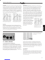 7
7
-
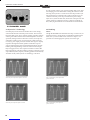 8
8
-
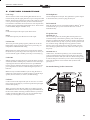 9
9
-
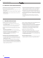 10
10
-
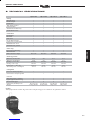 11
11
-
 12
12
-
 13
13
-
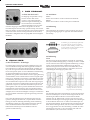 14
14
-
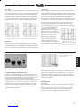 15
15
-
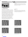 16
16
-
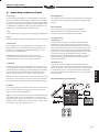 17
17
-
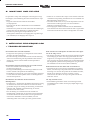 18
18
-
 19
19
-
 20
20
-
 21
21
-
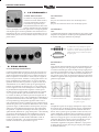 22
22
-
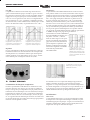 23
23
-
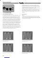 24
24
-
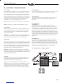 25
25
-
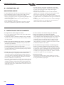 26
26
-
 27
27
-
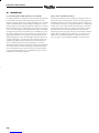 28
28
-
 29
29
-
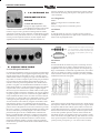 30
30
-
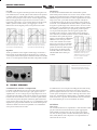 31
31
-
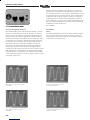 32
32
-
 33
33
-
 34
34
-
 35
35
-
 36
36
-
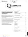 37
37
-
 38
38
-
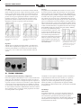 39
39
-
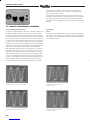 40
40
-
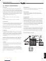 41
41
-
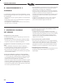 42
42
-
 43
43
-
 44
44
-
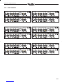 45
45
-
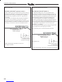 46
46
-
 47
47
-
 48
48


Quantum QC 310 Manuale utente
- Categoria
- Amplificatore per strumenti musicali
- Tipo
- Manuale utente
in altre lingue
- English: Quantum QC 310 User manual
- français: Quantum QC 310 Manuel utilisateur
- español: Quantum QC 310 Manual de usuario
- Deutsch: Quantum QC 310 Benutzerhandbuch