SELECT HINGES SL41HD Heavy Duty Swing Clear Geared Continous Hinges Manuale utente
- Tipo
- Manuale utente


INSTALLATION INSTRUCTIONS
Wide Throw • Swing Clear Geared Hinges
Ph: 800-423-1174 | Fax: 800-423-7107 | www.select-hinges.com
Information subject to
change without notice.
© 2021 SELECT Products Limited Printed in U.S.A. #IN-112321
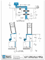
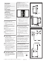
SL40 WIDE THROW SL41 SWING CLEAR
SEE BELOW
1-19/32"
1-1/8"
1-11/16"
SEE BELOW
1-29/32"
1-25/32"
2-1/4"
Req’d for rotation
1/16"
15/16"
Important Warranty Information:
The following actions will void any warranty, expressed or
implied:
QFailure to install the hinge according to manufacturer's
specifications and requirements. (For more information, visit
selecthingerequirements.com.)
QUse of fasteners other than those supplied with the hinge.
QUnauthorized field modifications, including alteration or
removal of the factory-applied lubricant, altering the original
finish or painting the hinge.
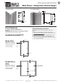
Door Clearances
For Square and Beveled-Edge Doors
: All uncut SL40 and SL41 hinges are non-handed
and templated. Model SL40 remains non-handed after cutting.
Model SL41 becomes handed after cutting.
YLX\PYLTLU[ZVUÄYLYH[LKLU[YHUJLZ
*1/8"
*1/8"
*1/8"
*1/8"– 3/16"
Single Door
Hinge side clearance
SL40 & SL41 Square Edge *5/16"
SL40 Beveled Edge *3/8"
SL41 Beveled Edge *11/32"
* Same clearance
as opposite side
Double Doors
(Pair)
Hinge side clearance
SL40 & SL41 Square Edge *5/16"
SL40 Beveled Edge *3/8"
SL41 Beveled Edge *11/32"

Ph: 800-423-1174 | Fax: 800-423-7107 | www.select-hinges.com Information subject to
change without notice.
© 2021 SELECT Products Limited Printed in U.S.A. #IN-112321
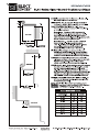
Fig. 2 Door Open 90˚
Fig. 1 Door Closed Position
6. Mark (or centerpunch) holes. If using
SDTF screws, go to Step 7. If using TF
or wood screws, drill holes at marked
locations.
QMetal door: Use #13 (.185") bit or
3/16" (.188”) bit
QWood door: Use 5/32" (.156") bit
7. Fasten door leaf to door using #3
Phillips drive and fasteners provided.
C. Attach Door to Frame
8. Position door at 90 degrees to the
frame. Shim door to the proper height
so the door aligns with the top screw
holes.
9. Install two screws at the top of hinge.
Remove shim and align remaining
holes. Install screws in middle and
bottom two holes.
10. Check door for proper swing and
clearance before installing remaining
screws.
Reinforcing & Rivnuts®
No hinge reinforcement is necessary except
on extremely high-frequency, extremely
heavy or extra-wide doors. Rivnuts are
recommended for use in the frame when
the door exceeds 450 lb. (max. 600 lb.).
NOTE: Only SELECT steel Rivnuts are to be
used with fire-rated SELECT hinges.
Grouted/Slushed-in Frames
For ease of installation, it is recommended
some sort of mudguard be installed behind
the frame. Do not use self-drilling, thread-
forming (SDTF) screws to drill into grouted
frames. If mudguards have not been used,
carefully drill pilot holes through frame and
remove grout for screw clearance. Do not
oversize holes in frame.
Fire-Rated Hinges
All stock SELECT hinges are 90-minute
UL-rated, without pins.
Please contact SELECT
for complete information
aboutits fire-rated hinges.
IMPORTANT: Top end of the hinge must be
flush with the top of the door.
IMPORTANT: If installing hinge on a
90-minute fire-rated wood door, mark or
centerpunch only one hole in each pair of
holes at the top and bottom of the door leaf.
DO NOT install the remaining screws in six-
hole pattern on the door leaf. See illustration
below.
How to Cut the Hinge to Fit
A. Keep hinge in “door closed” position
(Fig. 1).
B. Determine whether this will be a right-
hand or left-hand installation.
IMPORTANT: Cut only one end of hinge.
Cut end will be installed at the bottom.
Keep original templated six-hole pattern at
top end of hinge.
NOTE: SL40 is non-handed and remains
non-handed after cutting.
C. Using a metal-cutting saw, begin the
cut through the gear cap first.
NOTE: DO NOT cut through a set screw
bearing.
D. Reinstall any set screw bearing that
may have been cut o.
A. Prepare Frame
1. Shim hinge to 1/8" below the header to
allow for door clearance.
2. Hold hinge in “door open” position
(Fig. 2), making sure frame leaf
alignment flange (SL40) or frame face
portion of the frame leaf (SL41) is tight
against frame face.
3. Mark (or centerpunch) hole locations.
NOTE: TF screws and wood screws require
pilot holes at marked locations. SDTF
screws do not require pilot holes.
4. If using SDTF screws, go to Step 5. If
using TF or wood screws, drill holes
at marked locations. DO NOT attach
hinge to the frame at this time.
QMetal frame: Use #13 (.185") bit or
3/16" (.188”) bit
QWood frame: Use 5/32" (.156") bit
B. Attach Door to Hinge
5. Align the door leaf alignment flange or
the door leaf lip along the full length
of the door edge (even if the door is
slightly warped).
Frame Leaf Door Leaf
Tools Needed
QMetal-cutting saw
QTape measure
Q#13 or 3/16" drill bit
Q5/32" drill bit (wood frames/doors)
Q#3 Phillips drive
QShims
Parts Supplied
Q#12-24 self-drilling, thread-forming
(SDTF) 410 SS Phillips undercut
flathead screws
Optional Parts
Q#12 410 SS Phillips undercut
flathead wood screws
Q#12-24 thread-forming (TF)
410 SS Phillips undercut flathead
screws
QProtective gloves are
recommended
5/16" square edge
clearance (min.)
11/32" bevel edge
clearance (min.)
15/16"
1-29/32"
1-25/32"
2-1/4"
required for rotation
1/16"
5/16" square
edge
clearance (min.)
3/8" bevel edge
clearance (min.)
1-19/32"
1-11/16"
1-1/8"
15/16"
3-5/32"
1-3/4"
1-11/16"
7/16"
min
. clearance
required for
cap rotation
Open 90˚
1/4"
2-1/4"
clearance required for
cap rotation (min.)
1-1/2"
frame face for
mounting (min.)
27/32"
Open 90
-
 1
1
-
 2
2
-
 3
3
-
 4
4
-
 5
5


