Genius A453 Use And Installation Instructions
- Tipo
- Use And Installation Instructions

A453
APPARECCHIATURA ELETTRONICA PER BARRIERE
CONTROL BOARD FOR BARRIERS
PLATINE ELECTRONIQUE POUR BARRIERES
EQUIPO ELECTRÓNICO PARA BARRERAS
ELEKTRONISCHES GERÄT FÜR SCHRANKEN
ISTRUZIONI PER L’USO – NORME DI INSTALLAZIONE
USE AND INSTALLATION INSTRUCTIONS
INSTRUCTIONS POUR L’EMPLOI – NORMES D’INSTALLATION
INSTRUCCIONES PARA EL USO – NORMAS DE INSTALACIÓN
BETRIEBSANLEITUNG - INSTALLATIONSVORSCHRIFTEN

AVVERTENZE PER L’INSTALLATORE
OBBLIGHI GENERALI PER LA SICUREZZA
1) ATTENZIONE! È importante per la sicurezza delle persone seguire atten-
tamente tutta l’istruzione. Una errata installazione o un errato uso del
prodotto può portare a gravi danni alle persone.
2) Leggere attentamente le istruzioni prima di iniziare l’installazione del
prodotto.
3) I materiali dell’imballaggio (plastica, polistirolo, ecc.) non devono
essere lasciati alla portata dei bambini in quanto potenziali fonti di
pericolo.
4) Conservare le istruzioni per riferimenti futuri.
5) Questo prodotto è stato progettato e costruito esclusivamente per
l’utilizzo indicato in questa documentazione. Qualsiasi altro utilizzo non
espressamente indicato potrebbe pregiudicare l’integrità del pro-
dotto e/o rappresentare fonte di pericolo.
6) GENIUS declina qualsiasi responsabilità derivata dall’uso improprio o
diverso da quello per cui l’automatismo è destinato.
7) Non installare l’apparecchio in atmosfera esplosiva: la presenza di
gas o fumi infiammabili costituisce un grave pericolo per la sicurezza.
8) Gli elementi costruttivi meccanici devono essere in accordo con
quanto stabilito dalle Norme EN 12604 e EN 12605.
Per i Paesi extra-CEE, oltre ai riferimenti normativi nazionali, per ottene-
re un livello di sicurezza adeguato, devono essere seguite le Norme
sopra riportate.
9) GENIUS non è responsabile dell’inosservanza della Buona Tecnica
nella costruzione delle chiusure da motorizzare, nonché delle
deformazioni che dovessero intervenire nell’utilizzo.
10) L’installazione deve essere effettuata nell’osservanza delle Norme EN
12453 e EN 12445. Il livello di sicurezza dell’automazione deve essere
C+E.
11) Prima di effettuare qualsiasi intervento sull’impianto, togliere l’alimenta-
zione elettrica.
12) Prevedere sulla rete di alimentazione dell’automazione un interruttore
onnipolare con distanza d’apertura dei contatti uguale o superiore a
3 mm. È consigliabile l’uso di un magnetotermico da 6A con interruzio-
ne onnipolare.
13) Verificare che a monte dell’impianto vi sia un interruttore differenziale
con soglia da 0,03 A.
14) Verificare che l’impianto di terra sia realizzato a regola d’arte e
collegarvi le parti metalliche della chiusura.
15) L’automazione dispone di una sicurezza intrinseca antischiacciamen-
to costituita da un controllo di coppia. E' comunque necessario
verificarne la sogli di intervento secondo quanto previsto dalle Norme
indicate al punto 10.
16) I dispositivi di sicurezza (norma EN 12978) permettono di proteggere
eventuali aree di pericolo da Rischi meccanici di movimento, come
ad Es. schiacciamento, convogliamento, cesoiamento.
17) Per ogni impianto è consigliato l’utilizzo di almeno una segnalazione
luminosa nonché di un cartello di segnalazione fissato adeguatamen-
te sulla struttura dell’infisso, oltre ai dispositivi citati al punto “16”.
18) GENIUS declina ogni responsabilità ai fini della sicurezza e del buon
funzionamento dell’automazione, in caso vengano utilizzati compo-
nenti dell’impianto non di produzione GENIUS.
19) Per la manutenzione utilizzare esclusivamente parti originali GENIUS.
20) Non eseguire alcuna modifica sui componenti facenti parte del
sistema d’automazione.
21) L’installatore deve fornire tutte le informazioni relative al funzionamento
manuale del sistema in caso di emergenza e consegnare all’Utente
utilizzatore dell’impianto il libretto d’avvertenze allegato al prodotto.
22) Non permettere ai bambini o persone di sostare nelle vicinanze del
prodotto durante il funzionamento.
23) Tenere fuori dalla portata dei bambini radiocomandi o qualsiasi altro
datore di impulso, per evitare che l’automazione possa essere
azionata involontariamente.
24) Il transito tra le ante deve avvenire solo a cancello completamente
aperto.
25) L’Utente utilizzatore deve astenersi da qualsiasi tentativo di riparazione
o d’intervento diretto e rivolgersi solo a personale qualificato.
26) Tutto quello che non è previsto espressamente in queste istruzioni non è
permesso
IMPORTANT NOTICE FOR THE INSTALLER
GENERAL SAFETY REGULATIONS
1) ATTENTION! To ensure the safety of people, it is important that you read
all the following instructions. Incorrect installation or incorrect use of the
product could cause serious harm to people.
2) Carefully read the instructions before beginning to install the product.
3) Do not leave packing materials (plastic, polystyrene, etc.) within
reach of children as such materials are potential sources of danger.
4) Store these instructions for future reference.
5) This product was designed and built strictly for the use indicated in this
documentation. Any other use, not expressly indicated here, could
compromise the good condition/operation of the product and/or be
a source of danger.
6) GENIUS declines all liability caused by improper use or use other than
that for which the automated system was intended.
7) Do not install the equipment in an explosive atmosphere: the presence
of inflammable gas or fumes is a serious danger to safety.
8) The mechanical parts must conform to the provisions of Standards EN
12604 and EN 12605.
For non-EU countries, to obtain an adequate level of safety, the
Standards mentioned above must be observed, in addition to national
legal regulations.
9) GENIUS is not responsible for failure to observe Good Technique in the
construction of the closing elements to be motorised, or for any
deformation that may occur during use.
10) The installation must conform to Standards EN 12453 and EN 12445. The
safety level of the automated system must be C+E.
11) Before attempting any job on the system, cut out electrical power.
12) The mains power supply of the automated system must be fitted with
an all-pole switch with contact opening distance of 3mm or greater.
Use of a 6A thermal breaker with all-pole circuit break is recommended.
13) Make sure that a differential switch with threshold of 0.03 A is fitted
upstream of the system.
14) Make sure that the earthing system is perfectly constructed, and
connect metal parts of the means of the closure to it.
15) The automated system is supplied with an intrinsic anti-crushing safety
device consisting of a torque control. Nevertheless, its tripping threshold
must be checked as specified in the Standards indicated at point 10.
16) The safety devices (EN 12978 standard) protect any danger areas
against mechanical movement Risks, such as crushing, dragging, and
shearing.
17) Use of at least one indicator-light is recommended for every system,
as well as a warning sign adequately secured to the frame structure,
in addition to the devices mentioned at point “16”.
18) GENIUS declines all liability as concerns safety and efficient operation
of the automated system, if system components not produced by
GENIUS are used.
19) For maintenance, strictly use original parts by GENIUS.
20) Do not in any way modify the components of the automated system.
21) The installer shall supply all information concerning manual operation
of the system in case of an emergency, and shall hand over to the
user the warnings handbook supplied with the product.
22) Do not allow children or adults to stay near the product while it is
operating.
23) Keep remote controls or other pulse generators away from children,
to prevent the automated system from being activated involuntarily.
24) Transit through the leaves is allowed only when the gate is fully open.
25) The user must not attempt any kind of repair or direct action whatever
and contact qualified personnel only.
26) Anything not expressly specified in these instructions is not permitted.
CONSIGNES POUR L'INSTALLATEUR
RÈGLES DE SÉCURITÉ
1) ATTENTION! Il est important, pour la sécurité des personnes, de suivre à
la lettre toutes les instructions. Une installation erronée ou un usage erroné
du produit peut entraîner de graves conséquences pour les personnes.
2) Lire attentivement les instructions avant d'installer le produit.
3) Les matériaux d'emballage (matière plastique, polystyrène, etc.) ne
doivent pas être laissés à la portée des enfants car ils constituent des
sources potentielles de danger.
4) Conserver les instructions pour les références futures.
5) Ce produit a été conçu et construit exclusivement pour l'usage
indiqué dans cette documentation. Toute autre utilisation non
expressément indiquée pourrait compromettre l'intégrité du produit
et/ou représenter une source de danger.
6) GENIUS décline toute responsabilité qui dériverait d'usage impropre
ou différent de celui auquel l'automatisme est destiné.
7) Ne pas installer l'appareil dans une atmosphère explosive: la présence
de gaz ou de fumées inflammables constitue un grave danger pour
la sécurité.
8) Les composants mécaniques doivent répondre aux prescriptions des
Normes EN 12604 et EN 12605.
Pour les Pays extra-CEE, l'obtention d'un niveau de sécurité approprié
exige non seulement le respect des normes nationales, mais
également le respect des Normes susmentionnées.
9) GENIUS n'est pas responsable du non-respect de la Bonne Technique
dans la construction des fermetures à motoriser, ni des déformations
qui pourraient intervenir lors de l'utilisation.
10) L'installation doit être effectuée conformément aux Normes EN 12453
et EN 12445. Le niveau de sécurité de l'automatisme doit être C+E.
11) Couper l'alimentation électrique avant toute intervention sur l'installation.
12) Prévoir, sur le secteur d'alimentation de l'automatisme, un interrupteur
omnipolaire avec une distance d'ouverture des contacts égale ou
supérieure à 3 mm. On recommande d'utiliser un magnétothermique
de 6A avec interruption omnipolaire.
13) Vérifier qu'il y ait, en amont de l'installation, un interrupteur différentiel
avec un seuil de 0,03 A.
14) Vérifier que la mise à terre est réalisée selon les règles de l'art et y
connecter les pièces métalliques de la fermeture.
15) L'automatisme dispose d'une sécurité intrinsèque anti-écrasement,
formée d'un contrôle du couple. Il est toutefois nécessaire d'en vérifier
le seuil d'intervention suivant les prescriptions des Normes indiquées au
point 10.
16) Les dispositifs de sécurité (norme EN 12978) permettent de protéger
des zones éventuellement dangereuses contre les Risques mécaniques
du mouvement, comme l'écrasement, l'acheminement, le
cisaillement.

1
ITALIANO
APPARECCHIATURA ELETTRONICA PER BARRIERE
ISTRUZIONI PER L’USO - NORME DI INSTALLAZIONE
1. CARATTERISTICHE GENERALI
Questa centrale di comando per barriere, grazie alla elevata potenza del microprocessore di cui è dotata, offre un
ampio numero di prestazioni e regolazioni. Inoltre garantisce un elevato livello di sicurezza attiva, mediante il con-
trollo elettronico di potenza.
Un sofisticato controllo elettronico monitorizza costantemente il circuito di potenza ed interviene bloccando la
centrale in caso di anomalie che possano pregiudicare il corretto funzionamento della frizione elettronica. I settaggi
principali e i modi di funzionamento si effettuano mediante dip-switch mentre, le regolazioni dei tempi e della poten-
za del motore, si effettuano tramite trimmer posti sulla scheda elettronica. 7 LEDS incorporati indicano costantemen-
te lo stato degli ingressi, delle uscite ed eventuali avarie del circuito.
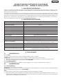
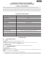
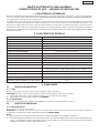
2. CARATTERISTICHE TECNICHE
3. COLLEGAMENTI
3.1 MORSETTIERA M1
3.1.1 Rete
Morsetti «17-18» (Neutro-Fase). Tensione di alimentazione 230 V~ - 50/60 Hz.
ATTENZIONE: per il corretto funzionamento della centrale è assolutamente necessario:
1) Rispettare la sequenza fase / neutro nel collegamento del’alimentazione, come indicato sulla scheda.
2) Effettuare il collegamento di terra al terminale “GROUND”.
3.1.2 Lampeggiatore
Morsetti «15-16» (Fase-Neutro). Utilizzare un lampeggiatore con tensione di funzionamento 230 Vca.
3.2 MORSETTIERA M2
3.2.1 Motoriduttore
Morsetti «12-13-14» (Open-Com-Close).
ATTENZIONE: nel caso di errato o mancato collegamento del motoriduttore la centrale si inibirà e segnalerà questo
stato mediante il lampeggio veloce del LED WORK.
Note:
1) Per la messa in opera dei cavi elettrici utilizzare adeguati tubi rigidi e/o flessibili.
2) Separare sempre i cavi di collegamento degli accessori a bassa tensione da quelli di alimentazione a 230 V~. Per
l’alimentazione dell’apparecchiatura bisogna prevedere dei cavi con sezione minima 1.5mm².Per evitare qual-
siasi interferenza utilizzare guaine separate.
enoizatnemilaidenoisneT .zH06/05-)%01-6+(~V032
atibrossaaznetoP W055
erotom.xamociraC W005
irossecca.xamociraC Am005cdV42
etneibmaarutarepmeT C°05+C°02-
enoizetorpidilibisuF 2
otnemanoiznufidehcigoL acitamotuA/ihcraP
arusuihc/arutrepaidopmeT issif.ces03
asuapidopmeT ).ces09a2ad(remmirtetimartelibalogeR
atnipsidazroF remmirtetimartelibalogeR
otnupsidopmeT ossif.ces1
enoisrevniidopmeT issif.ces2
otnematnellaridopmeT ossif.ces1
areittesromniissergnI
asroceniF/arusuihcelullecotoF/arusuihC/elatotarutrepA
arreT+eterenoizatnemilA/POTS/arusuihc-arutrepa
odnamocoidarreperottennoC nip5aitneveciroidaredehcS
oludomreperottennoC erotomollortnocoludoM
areittesromnieticsU erotoM/erotaiggepmaL/cdV42irosseccaenoizatnemilA
hctiws-pidnocilibanoizelesinoiznuF
otnemanoiznufididoM
arusuihcelullecotofotnematropmoC

2
ITALIANO
3.3 MORSETTIERA M3
3.3.1 Finecorsa apertura
Morsetti “10-11” (Circuito Normalmente Chiuso). Lo stato di questo ingresso è segnalato mediante il LED FCA. A questo
circuito va collegato il finecorsa di apertura. Questo circuito ha un effetto ritardato di un secondo, cioè una volta
premuto il finecorsa la barriera rallenta il suo movimento per un secondo.
3.3.2 Finecorsa chiusura
Morsetti “9-11” (Circuito Normalmente Chiuso). Lo stato di questo ingresso è segnalato mediante il LED FCC. A questo
circuito va collegato il finecorsa di chiusura. Questo circuito ha un effetto ritardato di un secondo, cioè una volta
premuto il finecorsa la barriera rallenta il suo movimento per un secondo.
3.3.3 Fotocellule protezione chiusura
Morsetti “8-11” (Circuito Normalmente Chiuso). Lo stato di questo ingresso è segnalato mediante il LED FOTO. A questo
circuito va collegato qualsiasi dispositivo di sicurezza (fotocellule, pressostato, detector, ect.) che, aprendo un con-
tatto, ha un effetto di sicurezza sul moto di chiusura. L’effetto in apertura è differente in funzione della programma-
zione effettuata tramite il dip-sw 3.
Nota bene: Per installare più dispositivi di sicurezza collegare i contatti NC in serie.
3.4 MORSETTIERA M4
3.4.1 Close
Morsetti «C-7» /Circuito Normalmente Aperto). Lo stato di questo ingresso è segnalato mediante il LED CLOSE. A
questo circuito va collegato un qualsiasi dispositivo (es. pulsante, radiocomando esterno, ect.) che, chiudendo un
contatto, genera un impulso di chiusura della barriera.
3.4.2 Start
Morsetti «6-7» (Circuito Normalmente Aperto). Lo stato di questo ingresso è segnalato mediante il LED START. A questo circuito
va collegato qualsiasi dispositivo (es. pulsante, radiocomando esterno, ect.) che, chiudendo un contatto, genera un impulso
di sola apertura o apertura / chiusura della barriera in base a come viene selezionato il dip-switch 1.
Nota bene: Per installare più datori di impulsi collegare i contatti in parallelo. E’ possibile bloccare la richiusura della
barriera collegando un orologio timer 24h in parallelo al circuito di START.
3.4.3 Stop
Morsetti “5-7” (Circuito Normalmente Chiuso). Lo stato di questo ingresso è segnalato mediante il LED STOP. A questo
circuito va collegato qualsiasi dispositivo (es. pulsante) che, aprendo un contatto, arresta il moto della barriera.
Nota bene: Se non vengono collegati dispositivi di STOP ponticellare l’ingresso. Per installare più dispositivi di STOP
collegare i contatti NC in serie.
3.4.4 Alimentazione accessori
Morsetti «3-4» (24 Vdc). ATTENZIONE: il carico max degli accessori è di 500 mA.
4. INSERIMENTO SCHEDA RICEVITORE PER TELECOMANDO
La centrale è predisposta per alloggiare un modulo radio-ricevitore. Per procedere all’installazione togliere l’ali-
mentazione elettrica e inserire il modulo nell’apposito connettore M5 all’interno della centrale. Seguire poi le istru-
zioni del radio-ricevitore per la memorizzazione del telecomando.
5. INSERIMENTO MODULO CONTROLLO MOTORE
La centrale è predisposta per alloggiare un modulo controllo motore (optional). Per procedere all’installazione
togliere l’alimentazione e inserire il modulo nell’apposito connettore M6 all’interno della centrale. Questo modulo,
in caso di urto con un ostacolo, blocca, inverte per 0,5 secondi il moto della barriera e inibisce la centrale, segnalato
dal lampeggio veloce del LED WORK. Solo dopo aver rimosso l’ostacolo ed un successivo comando di START permet-
te alla barriera di riprendere il ciclo impostato.
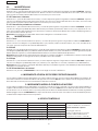
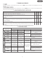
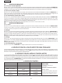
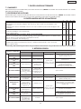
6. LEDS DI CONTROLLO
N.B.: In neretto la condizione dei leds con barriera a riposo.
SDELOSECCAOTNEPS
SKROWDEL
otnemivomniareirrab:oseccA
osopiraareirrab:otnepS
:ecolevoiggepmaL
erotomotnemagellocotarre-
acinortteleenoizirfotsaug-
ollortnocoludomotnevretnI-
POTSovittaniodnamoC ovittaodnamoC
TRATS otavittaodnamoC ovittaniodnamoC
ESOLC otavittaodnamoC ovittaniodnamoC
OTOF alullecotoF- etangepmisidezzeruciS etangepmiezzeruciS
CCF arusuihcasroceniF-otangepmisidasroceniF otangepmiasroceniF
ACF arutrepaasroceniF- otangepmisidasroceniF otangepmiasroceniF

3
ITALIANO
7. REGOLAZIONI CON TRIMMER
7.1 PAUSA
Per regolare la durata della pausa (per il funzionamento automatico) agire sul trimmer “BREAK”. La durata è regolabile
da 2 a 90 secondi.
7.2 FRIZIONE ELETTRONICA
Per regolare la soglia di intervento del sistema antischiacciamento è necessario agire sul trimmer “POWER”. Si racco-
manda di tarare questa coppia in conformità alla normativa vigente.
8. REGOLAZIONI CON DIP-SWITCH SW1
Nota bene: tutte le regolazioni vanno effettuate a centrale spenta e barriera chiusa.
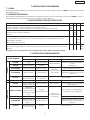
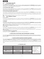
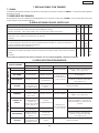
9. LOGICHE DI FUNZIONAMENTO
1234
IHCRAPACIGOL
eduihcolosESOLCoslupmi,erpaolosTRATSidoslupmI NO
eduihcolosESOLCidoslupmI.tceerpa-eduihc-erpa:TRATSidoslupmI FFO
ACITAMOTUAACIGOL
asuapidopmetopodeduihciR NO
asulcsE FFO
ARUSUIHCALULLECOTOFOTNEMANOIZNUF
ladeaccolbarutrepani,TRATSaccolbasuihces,etrevnideaccolbarusuihcnI
ednerpirongepmisid
NO
otomlietrevnideaccolB FFO
IHCRAPENOIZNUF
asuapnièesasuapidopmetetepir;arutrepa'letnarudTRATSidislupmietnesnoN NO
asulcsE FFO
AREIRRABOTATS
ISLUPMI
TRATSESOLCPOTSALULLECOTOF
ASUIHC erpAotteffenusseN
TRATSaccolB
TRATSaccolbootteffenusseN
emoc
3ws-pidad
ATREPA otteffenusseNeduihC
ARUSUIHCNI otomlietrevnIotteffenusseN
liaccolB
eotnemanoiznuf
POTSniav
otomlietrevnideaccolB
ARUTREPANI otteffenusseNotomlietrevnI
laeaccolbootteffenusseN
ademocednerpirongepmisid
3ws-pid
POTSNI
otomliednerpiR
osrevniosnesni
otomliednerpiR
arusuihcni
TRATSaccolB
ASUIHC
aleugese,erpA
eduihcireasuap
otteffenusseNTRATSaccoB
TRATSaccolbootteffenusseN
3ws-pidemoc
ASUAPNIATREPA
eduihciR
etnemataidemmi
idopmetetepiro
-pidemocasuap
4ws
eduihC
etnemataidemmi
liaccolB
eotnemanoiznuf
POTSniav
ongepmisidlaeTRATSaccolB
asuapidopmetanitsirpir
ARUSUIHCNI otomlietrevnIotteffenusseNetrevnideaccolB
ARUTREPANI
dootteffenusseN
emocetrevni
1ws-pid
otomlietrevnI
laeaccolbootteffenusseN
ademocednerpirongepmisid
3ws-pid
POTSNI
otomliednerpiR
osrevniosnesni
eduihCTRATSaccolB
PARCHIAUTOMATICA

4
ITALIANO
F1
2A
F2
5A
CPU
SW1
M5
-
+
-
+
BREAK POWER
M6
M4
M3 M2
M1
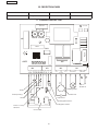
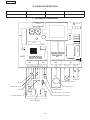
GROUND
LED WORK
A453
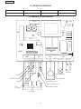
3 4 5 6 7 C 8 9 10 11
12 13 14 15 16 17N 18F
OPEN COM CLOSE
MOTORE
FLASH 220V
LINEA 220V
- +
N
F
230 V~
50/60 Hz
Lampeggiante
Motoriduttore
Condensatore
Apertura totale
Altre
sicurezze
Fotocellule
Blu
Stop
Finecorsa chiusura
Finecorsa apertura
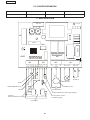
FUSIBILE PROTEZIONE FUSIBILE PROTEZIONE
F2 = 5A/250V - 5x20F1 = 2A/250V - 5x20 MotoreLogica / Accessori
10. FUSIBILI DI PROTEZIONE
11.SCHEMA DI COLLEGAMENTO
Close

5
ENGLISH
ELECTRONIC CONTROL UNIT FOR BARRIERS
USE INSTRUCTIONS - INSTALLATION INSTRUCTIONS
1. GENERAL CHARACTERISTICS
Thanks to its high powered microprocessor, this control unit for barriers offers a wide range of performances and
adjustments/settings. Moreover, it assures a high level of active security through electronic control of power.
A high-tech electronic control constantly monitors the power circuit and comes into action to shut down the control
unit in the event of faults which could jeopardise correct operation of the electronic clutch. The main settings and
operating modes are effected by dip switches. Time and motor power adjustments are effected by trimmers on the
electronic board. 7 built-in LEDS provide an on-going overview of the status of inputs, outputs and any circuit faults.
2. TECHNICAL SPECIFICATIONS
3. CONNECTIONS
3.1 M1 TERMINAL BOARD
3.1.1 Mains
Terminals «17-18» (Neutral-Phase). Power supply 230 V~ - 50/60 Hz.
ATTENTION: to ensure the control unit operates correctly:
1) respecting the connections, Phase / Neutral of power supply, as it has shown on the electronic board
2) earth connection must be made to the “GROUND” terminal.
3.1.2 Flashing-lamp
Terminals «15-16» (Phase-Neutral). Use a flashing-lamp with operating voltage of 230 Vca.
3.2 M2 TERMINAL BOARD
3.2.1 Gearmotor
Terminals «12-13-14» (Open-Com-Close).
ATTENTION: if the gearmotor is not connected or incorrectly connected, the control unit disables itself and this status
is signalled by rapid flashing of the WORK LED.
Notes:
1) To lay electric cables, use adequate rigid and/or flexible pipes.
2) Always separate the connection cables of low voltage accessories from the 230 V~ power cables. To supply power
to the equipment, use cables with minimum diameter of 1.5mm². To avoid any interference, use separate sheaths.
ylppusrewoP .zH06/05-)%01-6+(~V032
rewopdebrosbA W055
daolxamrotoM W005
daolxamseirosseccA Am005cdV42
erutarepmettneibmagnitarepO C°05+C°02-
sesufnoitcetorP 2
scigolnoitcnuF citamotuA/skraP
emitgnisolc/gninepO )dexif(.ces03
emitesuaP ).ces09ot2morf(elbatsujda-remmirT
ecroftsurhT elbatsujda-remmirT
emitgnitratS )dexif(.ces1
emitgnisreveR )dexif(.ces2
remitnoitareleceD )dexif(.ces1
stupnidraoblanimreT
-timilgnisolc-gninepO/sllecotohpgnisolC/gnisolC/gninepolatoT
dnuorG+ylppusrewopsniaMPOTS/hctiws
rotcennoclortnocoidaR dracrevieceroidaR
rotcennoceludoM eludomlortnocrotoM
stuptuodraoblanimreT rotoM/pmalgnihsalF/seirosseccaotylppusrewopcdV42
snoitcnufelbatceleshctiws-piD ruoivahebllecotohpgnisolC/sedomgnitarepO

6
ENGLISH
3.3 M3 TERMINAL BOARD
3.3.1 Opening limit-switch
Terminals “10-11” (Normally Closed Circuit). The status of this input is signalled by the FCA LED. This circuit should be
connected to the opening limit-switch. This circuit has a 1 second delayed effect, i.e. when the limit-switch is pressed,
the barrier movement decelerates for one second.
3.3.2 Closing limit-switch
Terminals “9-11” (Normally Closed Circuit). The status of this input is signalled by the FCC LED. This circuit should be
connected to the closing limit-switch. This circuit has a 1 second delayed effect, i.e. when the limit-switch is pressed, the
barrier movement decelerates for one second.
3.3.3 Closing protection photocells
Terminals “8-11” (Normally Closed Circuit). The status of this input is signalled by the FOTO LED. This circuit should be
connected to any safety device (photocells, pressure switch, detector, etc.) which, by opening a contact, has a
security effect on the closing movement. The effect on opening is different, according to programming with dip-sw
3.
NB.: To install several safety devices, connect the NC contacts in series.
3.4 M4 TERMINAL BOARD
3.4.1 Close
Terminals «C-7» (Normally Open Circuit ). The status of this input is signalled by the CLOSE LED. This circuit should be
connected to any device (push-button, external radio control, etc.) which, by closing a contact, generates a barrier
closing pulse.
3.4.2 Start
Terminals «6-7» (Normally Open Circuit). The status of this input is signalled by the START LED. This circuit should be
connected to any device (push-button, external radio control, etc.) which, by closing a contact, generates a barrier
opening only or opening / closing pulse according to how dip-switch 1 is selected.
N.B.: To install several pulse generators, connect the contacts in parallel. Barrier re-closure can be locked by connecting
a 24h timer clock in parallel with the START circuit.
3.4.3 Stop
Terminals “5-7” (Normally Closed Circuit ). The status of this input is signalled by the STOP LED. This circuit should be
connected to any device (e.g. push-button) which, by opening a contact, stops barrier movement.
N.B.: If no STOP devices are connected, jumper connect the input. To install several STOP devices, connect the NC
contacts in series.
3.4.4 Power supply to accessories
Terminals «3-4» (24 Vdc). ATTENTION: maximum load of accessories is 500 mA.
4. INSTALLING A RECEIVER CARD FOR REMOTE-CONTROL
The control unit is designed to house a 5-pin radio-receiver module. To install, cut out power and fit the module in the
appropriate M5 connector inside the control unit. Then follow the radio-receiver instructions for memory-storing the
remote-control.
5. INSTALLING THE MOTOR CONTROL MODULE
The control unit is designed to house a motor control module (optional). To install, cut out power and fit the module in
the appropriate M6 connector inside the control unit. In case of impact with an obstacle, this module stops, reverses
barrier motion for 0.5 seconds and disables the control unit, signalling this by a rapidly flashing WORK LED. This module
allows the barrier to resume its set cycle only after the obstacle has been removed and another START command
given.
6. CONTROL LEDS
N.B.: LED statuses with barrier at rest shown in bold.
SDELNOFFO
DELKROW
gnivomreirrab:NO
tsertareirrab:FFO
:gnihsalfdipaR
yltcerrocnirotom-
detcennoc
tluafhctulccinortcele-
deppirteludomlortnoc-
POTSevitcanidnammoC detavitcadnammoC
TRATS detavitcadnammoC evitcanidnammoC
ESOLC detavitcadnammoC evitcanidnammoC
OTOF llecotohP-
secivedytefaS
degagnesid
secivedytefaS
degagne
CCF hctiws-timilgnisolC-degagnesidhctiws-timiL degagnehctiws-timiL
ACF hctiws-timilgninepO- degagnesidhctiws-timiL degagnehctiws-timiL

7
ENGLISH
7. TRIMMER ADJUSTMENTS
7.1 PAUSE
To set pause duration, (for automatic operation) use the “BREAK” trimmer. Duration can be adjusted from 2 to 90
seconds.
7.2 ELECTRONIC CLUTCH
To set the tripping threshold of the anti-crushing system, use the “POWER”trimmer. You are recommended to set this
torque to the current regulations.
8. ADJUSTMENTS WITH DIP-SWITCH SW1
NB.: all adjustments/settings must be made with the control unit OFF and barrier closed.
9. FUNCTION LOGICS
1234
CIGOLSKRAP
ylnosesolceslupESOLC,ylnosnepoeslupTRATS NO
ylnosesolceslupESOLC.ctesnepo-sesolc-snepo:eslupRATS FFO
CIGOLCITAMOTUA
.emitesuapretfasesolc-eR NO
delbasiD FFO
NOITAREPOLLECOTOHPGNISOLC
dnaskcolgnineponehw,TRATSskcoldesolcfi,sesreverdnaskcolgnisolcnehW
.esaelernostratser
NO
.noitomsesreverdnaskcoL FFO
NOITCNUFSKRAP
.sutatsesuapnifiemitesuapstaeper;gninepognirudseslupTRATSeviecreptonseoD NO
delbasiD
SUTATSREIRRAB
SESLUP
TRATSESOLCPOTSLLECOTOHP
DESOLC snepOtceffeoN
TRATSskcoL
repTRATSskcolrotceffeoN
3ws-pid
NEPO tceffeoNsesolC
GNISOLC noitomsesreveRtceffeoN
noitarepospotS
otniseogdna
sutatsPOTS
noitomsesreverdnaskcoL
GNINEPO tceffeoNnoitomsesreveR
no,dnaskcolrotceffeoN
3ws-pidrepstratser,esaeler
DEPPOTS
ninoitomstratseR
noitceridesrever
otnoitomstratseR
esolc
TRATSskcoL
DESOLC
sesuap,snepO
sesolc-erdna
tceffeoNTRATSskcoL
repTRATSskcolrotceffeoN
3ws-pid
ESUAPNONEPO
sesolC
royletaidemmi
esuapstaeper
4ws-pidrepemit
sesolC
yletaidemmi
noitarepospotS
otniseogdna
sutatsPOTS
,esaelerno,dnaTRATSskcoL
emitesuapsteser
GNISOLC noitomsesreveRtceffeoNsesreverdnaskcoL
GNINEPO
rotceffeoN
-pidrepsesrever
1ws
noitomsesreveR
no,dnaskcolrotceffeoN
3ws-pidrepstratser,esaeler
DEPPOTS
ninoitomstratseR
noitceridesrever
sesolCTRATSskcoL
PARKS
AUTOMATIC

8
ENGLISH
F1
2A
F2
5A
CPU
SW1
M5
-
+
-
+
BREAK POWER
M6
M4
M3 M2
M1
GROUND
LED WORK
A453
3 4 5 6 7 C 8 9 10 11
12 13 14 15 16 17N 18F
OPEN COM CLOSE
MOTORE
FLASH 220V
LINEA 220V
- +
N
F
230 V~
50/60 Hz
Flashing-lamp
Gearmotor
Capacitor
Total opening
Other safety
devices
Photocells
Blu
Stop
Closing limit-switch
Opening limit-switch
FUSE PROTECTION FUSE PROTECTION
F2 = 5A/250V - 5x20F1 = 2A/250V - 5x20 MotorLogic / accessories
10. PROTECTION FUSES
11. CONNECTION LAY-OUT
Close

9
FRANÇAIS
ARMOIRE ÉLECTRONIQUE POUR BARRIÈRES
INSTRUCTIONS POUR L'EMPLOI - NORMES D'INSTALLATION
1. CARACTÉRISTIQUES GÉNÉRALES
Cette centrale de commande pour barrières, grâce à la grande puissance du microprocesseur dont elle est dotée,
offre un grand nombre de performances et de réglages. Elle garantit également un haut niveau de sécurité active,
grâce au contrôle électronique de la puissance.
Un contrôle électronique sophistiqué surveille constamment le circuit de puissance et intervient en bloquant la cen-
trale en cas d'anomalies risquant de compromettre le fonctionnement correct de l'embrayage électronique. On
effectue les principaux réglages et les modes de fonctionnement au moyen d'un dip-switche tandis qu'on règle les
temps et la puissance du moteur, par l'intermédiaire de trimmers situés sur la platine électronique. 7 LEDS incorporées
indiquent constamment l'état des entrées, des sorties et les pannes éventuelles du circuit.
2. CARACTÉRISTIQUES TECHNIQUES
3. CONNEXIONS
3.1 BORNIER M1
3.1.1 Réseau
Bornes «17-18» (Neutre-Phase). Tension d'alimentation 230 V~ - 50/60 Hz.
ATTENTION: pour le fonctionnement correct de la centrale il est absolument nécessaire:
1) Réspecter la séquence phase / neutre pendant la connexion de l’alimentation électrique, comme indiqué sur la fiche.
2) réaliser la connexion de terre au terminal “GROUND”.
3.1.2 Lampe clignotante
Bornes «15-16» (Phase-Neutre). Utiliser une lampe clignotante avec une tension de fonctionnement de 230 Vca.
3.2 BORNIER M2
3.2.1 Motoréducteur
Bornes «12-13-14» (Open-Com-Close).
ATTENTION: en cas de connexion erronée ou absente du motoréducteur, la centrale sera inhibée et signalera cet
état à travers le clignotement rapide de la LED WORK.
Remarques:
1) Pour la pose des câbles électriques, utiliser des tuyaux rigides et/ou flexibles adéquats.
2) Toujours séparer les câbles de raccordement des accessoires à basse tension des câbles d'alimentation à 230V~. Pour
l'alimentation de l'armoire, prévoir des câbles d'une section minimum 1,5 mm
2
. Pour éviter toute perturbation, utiliser des
gaines séparées.
noitatnemila'dnoisneT .zH06/05-)%01-6+(~V032
eébrosbaecnassiuP W055
ruetomixamegrahC W005
seriosseccaixamegrahC Am005ccV42
noitasilitu'derutarépmeT C°05+C°02-
noitcetorpedselbisuF 2
tnemennoitcnofedseuqigoL euqitamotuA/scraP
erutemref/erutrevuo'dspmeT sexifs03
esuapedspmeT )s09à2ed(remmirtnu'deriaidémretni'lrapelbalgéR
eéssuopedecroF remmirtnu'deriaidémretni'lrapelbalgéR
egarramédedspmeT exifs1
noisrevni'dspmeT sexifs2
tnemessitnelaredspmeT exifs1
reinrobseértnE
niF/erutemrefedselullecotohP/erutemreF/elatoterutrevuO
+uaesérnoitatnemilA/POTS/erutemref-erutrevuo'desruoced
erreT
ednammocoidarruopruetcennoC sehcorb5àoidarsruetpecérsedsetraC
eludomruopruetcennoC ruetomudelôrtnocedeludoM
reinrobseitroS
/etnatongilcepmaL/ccV42seriosseccasednoitatnemilA
ruetoM
ehctiws-pidcevaselbannoitceléssnoitcnoF
selullecotohpsedtnemetropmoC/tnemennoitcnofedsedoM
erutemrefed

10
FRANÇAIS
3.3 BORNIER M3
3.3.1 Fin de course d'ouverture
Bornes “10-11” (Circuit Normalement Fermé). L'état de cette entrée est signalé par la LED FCA. Connecter à ce circuit
le fin de course d'ouverture. Ce circuit a un effet retardé d'une seconde, c'est à dire qu'une fois que le fin de course
a été enfoncé, la barrière ralentit son mouvement pendant une seconde.
3.3.2 Fin de course de fermeture
Bornes “9-11” (Circuit Normalement Fermé). L'état de cette entrée est signalé par la LED FCC. Connecter à ce circuit
le fin de course de fermeture. Ce circuit a un effet retardé d'une seconde, c'est à dire qu'une fois que le fin de course
a été enfoncé, la barrière ralentit son mouvement pendant une seconde.
3.3.3 Photocellules de protection de la fermeture
Bornes “8-11” (Circuit Normalement Fermé). L'état de cette entrée est signalé par la LED FOTO. Connecter à ce circuit
un dispositif de sécurité quelconque (photocellules, pressostat, detector, etc.) qui, en ouvrant un contact, a un effet de
sécurité sur le mouvement de fermeture. L'effet en ouverture est différent en fonction de la programmation effectuée
par l'intermédiaire du dip-sw 3.
Nota bene: pour installer plusieurs dispositifs de sécurité, connecter les contacts NF en série.
3.4 BORNIER M4
3.4.1 Close
Bornes «C-7» (Circuit Normalement Ouvert). L'état de cette entrée est signalé par la LED CLOSE. Connecter à ce
circuit un dispositif quelconque (ex. poussoir, radiocommande externe, etc.) qui, en fermant un contact, génère une
impulsion de fermeture de la barrière.
3.4.2 Start
Bornes «6-7» (Circuit Normalement Ouvert). L'état de cette entrée est signalé par la LED START. Connecter à ce circuit un
dispositif quelconque (ex. poussoir, radiocommande externe, etc.) qui, en fermant un contact, génère une impulsion uniquement
d'ouverture ou d'ouverture / fermeture de la barrière suivant la façon dont on sélectionne le dip-switche 1.
Nota bene: pour installer plusieurs générateurs d'impulsions, connecter les contacts en parallèle. Il est possible de bloquer la
refermeture de la barrière en connectant une horloge temporisateur 24h en parallèle au circuit de START.
3.4.3 Stop
Bornes “5-7” (Circuit Normalement Fermé). L'état de cette entrée est signalé par la LED STOP. Connecter à ce circuit un
dispositif quelconque (ex. poussoir) qui, en ouvrant un contact, arrête le mouvement de la barrière.
Nota bene: Si on ne connecte aucun dispositif de STOP, ponter l'entrée. Pour installer plusieurs dispositifs de STOP, connecter les
contacts NF en série.
3.4.4 Alimentation des accessoires
Bornes «3-4» (24 Vcc). ATTENTION: la charge maxi des accessoires est de 500 mA.
4. MISE EN PLACE DE LA CARTE DU RÉCEPTEUR POUR TÉLÉCOMMANDE
La centrale est disposée pour loger un module récepteur radio. Pour l'installation, couper le courant et embrocher le module
sur le connecteur M5 spécifique à l'intérieur de la centrale. Suivre ensuite les instructions du récepteur radio pour la mémorisation
de la télécommande.
5. MISE EN PLACE DU MODULE DE CONTRÔLE DU MOTEUR
La centrale est disposée pour loger un module de contrôle du moteur (option). Pour l'installation, couper le courant et embrocher
le module sur le connecteur M6 spécifique à l'intérieur de la centrale. Ce module, en cas de choc contre un obstacle, bloque
et invertit pendant 0,5 secondes le mouvement de la barrière et inhibe la centrale, signalé par le clignotement rapide de la
LED WORK. Seules l'élimination de l'obstacle et une commande de START successive permet à la barrière de reprendre le
cycle sélectionné.
6. LEDS DE CONTRÔLE
N.B.: On indique en caractères gras la condition des leds avec la barrière au repos.
SDELEÉMULLAETNIETÉ
KROWDEL
neerèirrab:eémullA
tnemevuom
soperuaerèirrab:etnietÉ
:edipartnemetongilC
ruetomudeénorrenoixennoc-
egayarbme'ledennap-
euqinortcelé
edeludomudnoitnevretnI-
elôrtnoc
POTSevitcaniednammoC evitcaednammoC
TRATS eévitcaednammoC evitcaniednammoC
ESOLC eévitcaednammoC evitcaniednammoC
OTOF elullecotohP- seégagnesédsétirucéS seégagnesétirucéS
CCF edesruocedniF-
erutemref
esruocedniF
égagneséd
esruocedniF
égagne
ACF esruocedniF-
erutrevuo'd
esruocedniF
égagneséd
esruocedniF
égagne

11
FRANÇAIS
7. RÉGLAGES AU MOYEN DU TRIMMER
7.1 PAUSE
Pour régler la durée de la pause (pour le fonctionnement automatique) agir sur le trimmer “BREAK”. La durée est
réglable de 2 à 90 secondes.
7.2 EMBRAYAGE ÉLECTRONIQUE
Pour régler le seuil d'intervention du système anti-écrasement, agir sur le trimmer “POWER”. On recommande d'étalonner
ce couple conformément aux normes en vigueur.
8. RÉGLAGES AU MOYEN DU DIP-SWITCHE SW1
Nota bene: effectuer tous les réglages avec la centrale éteinte et barrière fermée.
9. LOGIQUES DE FONCTIONNEMENT
1234
SCRAPEUQIGOL
tnemeluesemrefESOLCnoislupmi,tnemelueservuo:TRATSnoislupmI NO
tnemeluesemrefESOLCnoislupmi,.cteervuo-emref-ervuo:TRATSnoislupmI FFO
EUQITAMOTUAEUQIGOL
esuapedspmetelsèrpaemrefeR NO
eulcxE FFO
ERUTEMREFEDELULLECOTOHPTNEMENNOITCNOF
uateeuqolb,erutrevuone;TRATSeuqolb,eémreftseelleis;titrevniteeuqolberutemrefnE
dnerpertnemegagneséd
NO
tnemevuomeltitrevniteeuqolB FFO
SCRAPNOITCNOF
neelleisesuapedspmeteletèpér;erutrevuo'ltnarudTRATSsnoislupmiselsaptioçereN
esuap
NO
eulcxE FFO
ERÈIRRABTATÉ
SNOISLUPMI
TRATSESOLCPOTSELULLECOTOHP
EÉMREF ervuOteffenucuA
TRATSeuqolB
TRATSeuqolbuoteffenucuA
3ws-pideltnavius
ETREVUO teffenucuAemreF
ERUTEMREFNE
eltitrevnI
tnemevuom
teffenucuA
eleuqolB
tetnemennoitcnof
POTSneav
eltitrevniteeuqolB
tnemevuom
ERUTREVUONE teffenucuA
eltitrevnI
tnemevuom
uateeuqolbuoteffenucuA
dnerpertnemegagneséd
3ws-pideltnavius
POTSNE
eldnerpeR
netnemevuom
esrevnisnes
eldnerpeR
netnemevuom
erutemref
TRATSeuqolB
EÉMREF
aletucéxe,ervuO
emreferteesuap
teffenucuATRATSeuqolB
TRATSeuqolbuoteffenucuA
3ws-pideltnavius
ESUAPNEETREVUO
emrefeR
uotnemetaidémmi
edspmeteletèpér
eltnaviusesuap
4ws-pid
emreF
tnemetaidémmi
eleuqolB
tetnemennoitcnof
POTSneav
uateTRATSeuqolB
eltilbatértnemegagneséd
esuapedspmet
ERUTEMREFNE
eltitrevnI
tnemevuom
teffenucuAtitrevniteeuqolB
ERUTREVUONE
uoteffenucuA
eltnaviustitrevni
1ws-pid
eltitrevnI
tnemevuom
uateeuqolbuoteffenucuA
dnerpertnemegagneséd
3ws-pideltnavius
POTSNE
eldnerpeR
netnemevuom
esrevnisnes
emreFTRATSeuqolB
PARCS
AUTOMATIQUE

12
FRANÇAIS
F1
2A
F2
5A
CPU
SW1
M5
-
+
-
+
BREAK POWER
M6
M4
M3 M2
M1
GROUND
LED WORK
A453
3 4 5 6 7 C 8 9 10 11
12 13 14 15 16 17N 18F
OPEN COM CLOSE
MOTORE
FLASH 220V
LINEA 220V
- +
N
F
230 V~
50/60 Hz
Lampe clignotante
Motoréducteur
Condensateur
Ouverture totale
Autres sécurités
Photocellules
Blu
Stop
Fin de course de fermeture
Fin de course d'ouverture
FUSIBLE PROTECTION FUSIBLE PROTECTION
F2 = 5A/250V - 5x20F1 = 2A/250V - 5x20 MoteurLogique / Accessoires
10. FUSIBLES DE PROTECTION
11. SCHÉMA DE CONNEXION
Close

13
ESPAÑOL
EQUIPO ELECTRÓNICO PARA BARRERAS
INSTRUCCIONES DE USO - NORMAS DE INSTALACIÓN
1. CARACTERÍSTICAS GENERALES
Esta central de mando para barreras, gracias a la elevada potencia del microprocesador con el que está equipada,
ofrece un amplio número de prestaciones y regulaciones. Además, garantiza un elevado nivel de seguridad activa,
por medio del control electrónico de potencia.
Un sofisticado control electrónico monitoriza constantemente el circuito de potencia e interviene bloqueando la
central en caso de anomalías que puedan perjudicar el correcto funcionamiento del embrague electrónico. Las
principales configuraciones y los modos de funcionamiento se efectúan mediante dip-switch, mientras que las
regulaciones de los tiempos y de la potencia del motor, se efectúan por medio de trimmer ubicados en la tarjeta
electrónica. 7 DIODOS incorporados indican constantemente el estado de las entradas, de las salidas y las eventuales
averías del circuito.
2. CARACTERÍSTICAS TÉCNICAS
3. CONEXIONES
3.1 REGLETA DE BORNES M1
3.1.1 Red
Bornes «17-18» (Neutro-Fase). Tensión de alimentación 230 V~ - 50/60 Hz.
ATENCIÓN: para el correcto funcionamiento de la central es absolutamente necesario:
1) respetar el orden fase / neutro de alimentacion, como indicado en la tableta
2) efectuar la conexión de tierra al terminal “GROUND”.
3.1.2 Destellador
Bornes «15-16» (Fase-Neutro). Utilizar un destellador con tensión de funcionamiento 230 Vca.
3.2 REGLETA DE BORNES M2
3.2.1 Motorreductor
Bornes «12-13-14» (Open-Com-Close).
ATENCIÓN: en caso de conexión incorrecta o de falta de conexión del motorreductor, la central se inhibirá e
indicará este estado por medio del destello rápido del DIODO WORK.
Notas:
1) Para la puesta en obra de los cables eléctricos, utilice adecuados tubos rígidos y/o flexibles.
2) Separare siempre los cables de conexión relativos a los accesorios de baja tensión, de los cables de alimentación
a 230 V~. Para la alimentación del equipo hay que prever cables con una sección mínima de 1.5mm². Para evitar
cualquier interferencia, utilice vainas separadas.
nóicatnemilaednóisneT .zH06/05-)%01-6+(~V032
adibrosbaaicnetoP W055
rotomamixámagraC W005
soiroseccaamixámagraC Am005cdV42
etneibmaarutarepmeT C°05+C°02-
nóiccetorpedselbisuF 2
otneimanoicnufedsacigóL acitámotuA/sotneimacrapA
erreic/arutrepaedopmeiT sojif.ges03
asuapedopmeiT ).ges09a2ed(remmirtedoidemropelbalugeR
ejupmeedazreuF remmirtedoidemropelbalugeR
euqnarraedopmeiT ojif.ges1
nóisrevniedopmeiT sojif.ges2
nóicarelecededopmeiT ojif.ges1
senrobedatelgernesadartnE
arerracedniF/erreicsalulécotoF/erreiC/latotarutrepA
arreiT+dernóicatnemilA/POTS/erreic-arutrepa
odnamoidararaprotcenoC senip5edserotpecer-oidarsatejraT
oludómaraprotcenoC rotomlortnocoludóM
senrobedatelgernesadilaS rotoM/rodalletseD/cdV42soiroseccanóicatnemilA
hctiws-pidnocselbanoiccelessenoicnuF
salulécotofotneimatropmoC/otneimanoicnufedsodoM
erreic

14
ESPAÑOL
3.3 REGLETA DE BORNES M3
3.3.1 Fin de carrera apertura
Bornes “10-11” (Circuito Normalmente Cerrado). El estado de esta entrada está indicado mediante el DIODO FCA.
A este circuito debe conectarse el fin de carrera de apertura. Este circuito tiene un efecto retardado de un segundo,
es decir, una vez presionado el fin de carrera la barrera decelera su movimiento durante un segundo.
3.3.2 Fin de carrera cierre
Bornes “9-11” (Circuito Normalmente Cerrado). El estado de esta entrada está indicado mediante el DIODO FCC. A
este circuito debe conectarse el fin de carrera de cierre. Este circuito tiene un efecto retardado de un segundo, es
decir, una vez presionado el fin de carrera la barrera decelera su movimiento durante un segundo.
3.3.3 Fotocélulas protección cierre
Bornes “8-11” (Circuito Normalmente Cerrado). El estado de esta entrada está indicado mediante el DIODO FOTO.
A este circuito debe conectarse cualquier dispositivo de seguridad (fotocélulas, presóstato, detector, etc.) que,
abriendo un contacto, tiene un efecto de seguridad sobre el movimiento de cierre. El efecto en apertura es diferente
en función de la programación efectuada por medio del dip-sw 3.
Nota: Para instalar varios dispositivos de seguridad, conecte los contactos NC en serie.
3.4 REGLETA DE BORNES M4
3.4.1 Close
Bornes «C-7» (Circuito Normalmente Abierto). El estado de esta entrada está indicado mediante el DIODO CLOSE.
A este circuito debe conectarse cualquier dispositivo (ej. pulsador, radiomando externo, etc.) que, cerrando un
contacto, genera un impulso de cierre de la barrera.
3.4.2 Start
Bornes «6-7» (Circuito Normalmente Abierto). El estado de esta entrada está indicado mediante el DIODO START. A
este circuito debe conectarse cualquier dispositivo (ej. pulsador, radiomando externo, etc.) que, cerrando un contacto,
genera un impulso de sólo apertura o apertura / cierre de la barrera, en base a cómo se selecciona el dip-switch 1.
Nota: Para instalar varios emisores de impulsos conecte los contactos en paralelo. Se puede bloquear el cierre de
la barrera conectando un reloj timer 24h en paralelo al circuito de START.
3.4.3 Stop
Bornes “5-7” (Circuito Normalmente Cerrado). El estado de esta entrada está indicado por medio del DIODO STOP. A este
circuito debe conectarse cualquier dispositivo (ej. pulsador) que, abriendo un contacto, detiene el movimiento de la barrera.
Nota: Si no se conectan dispositivos de STOP, puenteen la entrada. Para instalar varios dispositivos de STOP conecten los
contactos NC en serie.
3.4.4 Alimentación accesorios
Bornes «3-4» (24 Vdc). ATENCIÓN: la carga máxima de los accesorios es de 500 mA.
4. INTRODUCCIÓN DE LA TARJETA RECEPTOR PARA TELEMANDO
La central está predispuesta para alojar un módulo radio-receptor. Para proceder a la instalación, quite la alimentación
eléctrica e introduzca el módulo en el específico conector M5 en el interior de la central. A continuación siga las instrucciones
del radio-receptor para la memorización del telemando.
5. INTRODUCCIÓN DEL MÓDULO CONTROL MOTOR
La central está predispuesta para alojar un módulo de control motor (opcional). Para proceder a la instalación quite la
alimentación e introduzca el módulo en el específico conector M6 en el interior de la central. Este módulo, en caso de
choque con un obstáculo, bloquea, invierte durante 0,5 segundos el movimiento de la barrera e inhibe la central, indicado
por el destello rápido del DIODO WORK. Sólo después de haber eliminado el obstáculo, un sucesivo mando de START permite
a la barrera reanudar el ciclo programado.
6. DIODOS DE CONTROL
NOTA: En negrita se indica la condición de los diodos con barrera en reposo.
SODOIDODIDNECNEODAGAPA
KROWODOID
nearerrab:odidnecnE
otneimivom
osopernearerrab:odagapA
:odipárolletseD
rotomlednóixenocatcerrocni-
ocinórtceleeugarbmeaíreva-
lortnocoludómnóicnevretnI-
POTSovitcaniodnaM ovitcaodnaM
TRATS odavitcaodnaM ovitcaniodnaM
ESOLC odavitcaodnaM ovitcaniodnaM
OTOF alulécotoF-
dadirugesed.psiD
serbil
dadirugesed.psiD
sodapuco
CCF arerracedniF-
erreic
erbilarerracedniF
arerracedniF
odapuco
ACF arerracedniF-
arutrepa
erbilarerracedniF
arerracedniF
odapuco

15
ESPAÑOL
7. REGULACIONES CON TRIMMER
7.1 PAUSA
La duración de la pausa (para el funcionamiento automático) se regula con el trimmer “BREAK”. La duración puede regularse
de 2 a 90 segundos.
7.2 EMBRAGUE ELECTRÓNICO
El umbral de intervención del sistema antiaplastamiento se regula con el trimmer “POWER”. Se aconseja tarar este par de
conformidad con la normativa vigente.
8. REGULACIONES CON DIP-SWITCH SW1
Nota: todas las regulaciones deben realizarse con la central apagada y la barrera cerrada.
9. LÓGICAS DE FUNCIONAMIENTO
1234
SOTNEIMACRAPAACIGÓL
arreicolósESOLCedoslupmi,erbaolósTRATSedoslupmI NO
arreicolósESOLCedoslupmI.cteerba-arreic-erba:TRATSedoslupmI FFO
ACITÁMOTUAACIGÓL
asuapedopmeitledséupsedoveunedarreiC NO
adiulcxE FFO
ERREICALULÉCOTOFOTNEIMANOICNUF
yaeuqolbarutrepane,TRATSaeuqolbadarrecátseis,etreivnieaeuqolbarreicnE
otneimivomleadunaerarebilesodnauc
NO
otneimivomleetreivnieaeuqolB FFO
SOTNEIMACRAPANÓICNUF
neátseisasuapedopmeitetiper;arutrepaaletnarudTRATSedsoslupmiatcetedoN
asuap
NO
adiulcxE FFO
ARERRABODATSE
SOSLUPMI
TRATSESOLCPOTSALULÉCOTOF
ADARREC erbAotcefenúgniN
TRATSaeuqolB
aeuqolbootcefenúgniN
3ws-pidomocTRATS
ATREIBA otcefenúgniNarreiC
ERREICNE
leetreivnI
otneimivom
otcefenúgniN
leaeuqolB
otneimanoicnuf
POTSneavy
leetreivnieaeuqolB
otneimivom
ARUTREPANE otcefenúgniN
leetreivnI
otneimivom
yaeuqolbootcefenúgniN
adunaerarebilesodnauc
3ws-pidomoc
POTSNE
leadunaeR
neotneimivom
osrevnioditnes
leadunaeR
neotneimivom
erreic
TRATSaeuqolB
ADARREC
alazilaer,erbA
arreicyasuap
oveuned
otcefenúgniNTRATSaeuqoB
aeuqolbootcefenúgniN
3ws-pidomocTRATS
NEATREIBA
ASUAP
oveunedarreiC
etnemataidemni
leetipero
asuapedopmeit
4ws-pidomoc
arreiC
etnemataidemni
leaeuqolB
otneimanoicnuf
POTSneavy
esodnaucyTRATSaeuqolB
edopmeitleecelbatserarebil
asuap
ERREICNE
leetreivnI
otneimivom
otcefenúgniNetreivnieaeuqolB
ARUTREPANE
ootcefenúgniN
omocetreivni
1ws-pid
leetreivnI
otneimivom
yaeuqolbootcefenúgniN
adunaerarebilesodnauc
3ws-pidomoc
POTSNE
leadunaeR
neotneimivom
osrevnioditnes
arreiCTRATSaeuqolB
APARCAMIENTOSAUTOMÁTICA

16
ESPAÑOL
F1
2A
F2
5A
CPU
SW1
M5
-
+
-
+
BREAK POWER
M6
M4
M3 M2
M1
GROUND
LED WORK
A453
3 4 5 6 7 C 8 9 10 11
12 13 14 15 16 17N 18F
OPEN COM CLOSE
MOTORE
FLASH 220V
LINEA 220V
- +
N
F
230 V~
50/60 Hz
Destellador
Motorreductor
Condensador
Apertura total
Otros dispositivos
de seguridad
Fotocélulas
Blu
Stop
Fin de carrera cierre
Fin de carrera apertura
FUSIBLE PROTECCIÓN FUSIBLE PROTECCIÓN
F2 = 5A/250V - 5x20F1 = 2A/250V - 5x20 MotorLógica / Accesorios
10. FUSIBLES DE PROTECCIÓN
11. ESQUEMA DE CONEXIÓN
Close

17
DEUTSCH
ELEKTRONISCHES GERÄT FÜR SCHRANKEN
BETRIEBSANLEITUNG - MONTAGEVORSCHRIFTEN
1. ALLGEMEINE DATEN
Diese Steuereinheit für Schranken bietet dank der hohen Leistung des integrierten Mikroprozessors eine große Anzahl
an Einsatz- und Einstellungsmöglichkeiten. Darüber hinaus wird durch die elektronische Leistungssteuerung ein hohes
Niveau an aktiver Sicherheit gewährleistet.
Eine hoch entwickelte elektronische Steuerung überwacht ständig den Leistungskreis und sperrt die Einheit bei Störungen,
die den reibungslosen Betrieb der elektronischen Kupplung beeinträchtigen könnten. Die wichtigsten Einstellungen
und Funktionen werden über einen Dip-Schalter ausgeführt, die Einstellung der Zeiten und der Motorleistung erfolgt
über einen Trimmer auf der elektronischen Karte. 7 integrierte LED-Dioden zeigen den ständigen Zustand der Eingänge,
der Ausgänge sowie eventuelle Störungen des Schaltkreises an.
2. TECHNISCHE DATEN
3. ANSCHLÜSSE
3.1 KLEMMENLEISTE M1
3.1.1 Netz
Klemmen „17-18” (Nullleiter-Phase). Versorgungsspannung 230 V~ - 50/60 Hz.
ACHTUNG: Für den reibungslosen Betrieb der Steuereinheit ist folgeudes zu beachten:
1) Bei Stromanschluß die folge Phase / Nullleiter beachten, wie auf der Schaltschema anschliessen.
2) Erdanschluss unbedingt an der Klemme „GROUND” vorzunehmen.
3.1.2 Blinkleuchte
Klemmen „15-16” (Phase-Nullleiter). Eine Blinkleuchte mit Betriebsspannung 230 Vca einsetzen.
3.2 KLEMMENLEISTE M2
3.2.1 Getriebemotor
Klemmen „12-13-14” (Open-Com-Close).
ACHTUNG: Wenn der Getriebemotor unsachgemäß oder gar nicht angeschlossen ist, wird die Steuereinheit gesperrt
und signalisiert diesen Zustand durch schnelles Blinken der LED WORK.
Annmerkungen:
1) Für das Verlegen der Stromkabel sind geeignete starre und/oder flexible Rohre zu verwenden.
2) Die Kabel für den Anschluss des Zubehörs mit Niederspannung sind stets von den Kabeln mit Spannung 230 V~ zu
trennen. Für die Speisung des Gerätes sind Kabel mit einem Mindestquerschnitt von 1,5 mm² zu verwenden. Zur
Vermeidung von Interferenzen sind stets getrennte Ummantelungen zu verwenden.
gnunnapssgnugrosreV .zH06/05-)%01-6+(~V032
emhanfuasgnutsieL W055
rotoMtsaL.xaM W005
röhebuZtsaL.xaM Am005cdV42
trosgnulletsfuAmarutarepmeT C°05+C°02-
negnurehciS 2
nekigolsbeirteB beirtebkitamotuA/beirtebkraP
gnagrovßeilhcS/-sgnunffÖreuaD gnulletsnietseF.keS03
tieznesuaP ).keS09sib2nov(rablletsnieremmirTrebü
tfarkbuhcS rablletsnieremmirTrebü
tiezssalnA gnulletsnietseF.keS1
tiezsgnurhekmU gnulletsnietseF.keS2
tiezsgnusmerbbA gnulletsnietseF.keS1
etsielnemmelKfuaegnägniE
nellezotoF/gnußeilhcS/gnunffÖegidnätslloV
/gnagrovßeilhcS/-sgnunffÖretlahcsdnE/gnagrovßeilhcS
edrE+gnugrosrevzteN/PPOTS
gnureuetsknuFrüfrekcetS netrakregnäfpmeknuF-niP5
ludoMrüfrekcetS srotoMsedgnureuetSruzludoM
etsielnemmelKfuaegnägsuA rotoM/ethcuelknilB/cdV42röhebuZgnugrosreV
nenoitknuFerablhäwnanretlahcS-piDtiM
netrasbeirteB
gnagrovßeilhcSmiebnellezotoFredesiewsnoitknuF

18
DEUTSCH
3.3 KLEMMENLEISTE M3
3.3.1 Endschalter beim Öffnungsvorgang
Klemmen „10-11” (Ruhestromkreis). Der Status dieses Eingangs wird mit Hilfe der LED FCA signalisiert. An diese Schaltung
wird der Öffnungs-Endschalter angeschlossen. Dieser Schaltkreis hat eine um eine Sekunde verzögerte Wirkung, d.h.
wenn der Endschalter belegt wird, bremst die Schranke ihre Bewegung eine Sekunde lang ab.
3.3.2 Endschalter beim Schließvorgang
Klemmen „9-11” (Ruhestromkreis) Der Status dieses Eingangs wird mit Hilfe der LED FCC signalisiert. An diese Schaltung
wird der Schließ-Endschalter angeschlossen. Dieser Schaltkreis hat eine um eine Sekunde verzögerte Wirkung, d.h.
wenn der Endschalter belegt wird, bremst die Schranke ihre Bewegung eine Sekunde lang ab.
3.3.3 Fotozellen zum Schutz beim Schließvorgang
Klemmen „8-11” (Ruhestromkreis). Der Status dieses Eingangs wird mit Hilfe der LED FOTO signalisiert. An diese Schaltung werden
alle Sicherheitsvorrichtungen (Fotozellen, Druckschalter, Detektor usw.) angeschlossen, die durch Öffnung eines Kontaktes
eine Sicherheitswirkung auf die Schließbewegung haben. Die Wirkung beim Öffnungsvorgang unterscheidet sich je nach der
durch den Dip-Sw 3 vorgenommenen Programmierung.
Anmerkung: Zur Installation von mehreren Sicherheitsvorrichtungen sind die Ruhekontakte in Reihe zu schalten.
3.4 KLEMMENLEISTE M4
3.4.1 Close
Klemmen „C-7” (Arbeitsstromkreis). Der Status dieses Eingangs wird mit Hilfe der LED CLOSE signalisiert. An diese Schaltung wird
eine beliebige Vorrichtung angeschlossen (z.B. Taste, externe Funksteuerung usw.), die durch Schließen eines Kontaktes einen
Impuls für das Schließen der Schranke erzeugt.
3.4.2 Start
Klemmen „6-7” (Arbeitsstromkreis). Der Status dieses Eingangs wird mit Hilfe der LED START signalisiert. An diese Schaltung wird
eine beliebige Vorrichtung angeschlossen (z.B. Taste, externe Funksteuerung usw.), die durch Schließen eines Kontaktes einen
Impuls für das Öffnen oder für das Öffnen/Schließen der Schranke erzeugt, je nach der Anwahl auf dem Dip-Schalter 1.
Anmerkung: Zur Installation von mehreren Impulsgebern sind die Kontakte parallel zu schalten. Das erneute Schließen der
Schranke kann durch den Parallelanschluss einer 24h-Zeituhr an die START-Schaltung blockiert werden.
3.4.3 Stop
Klemmen „5-7” (Ruhestromkreis). Der Status dieses Eingangs wird mit Hilfe der LED STOP signalisiert. An diese Schaltung wird eine
beliebige Vorrichtung (z.B. Taste) angeschlossen, die durch das Öffnen eines Kontakts die Bewegung der Schranke stoppt.
Anmerkung: Wenn keine STOPP-Vorrichtungen angeschlossen werden, ist der Eingang zu überbrücken. Für den Einbau mehrerer
STOPP-Vorrichtungen sind die Ruhekontakte in Reihe zu schalten.
3.4.4 Speisung des Zubehörs
Klemmen „3-4” (24 Vdc). ACHTUNG: Die max. Last des Zubehörs beträgt 500 mA.
4. EINSETZEN DER EMPFÄNGERKARTE FÜR DIE FERNSTEUERUNG
Die Steuereinheit ist so ausgelegt, dass sie ein Funkempfänger-Modul aufnehmen kann. Für den Einbau die Stromversorgung
unterbrechen und dann das Modul in den entsprechenden Stecker M5 in der Steuereinheit einsetzen. Danach die
Bedienungsanweisungen des Funkempfängers für die Speicherung der Fernsteuerung befolgen.
5. EINSETZEN DES MOTOR-STEUERMODULS
Die Steuereinheit ist so ausgelegt, dass sie ein Motor-Steuermodul (optional) aufnehmen kann. Für den Einbau die Stromversorgung
unterbrechen und das Modul in den entsprechenden Stecker M6 in der Steuereinheit einsetzen. Beim Zusammenstoß mit einem
Hindernis bewirkt dieses Modul 0,5 Sekunden lang die Sperre/Umkehr der Bewegung der Schranke und hemmt die Steuereinheit.
Dies wird durch schnelles Aufblinken der LED WORK angezeigt. Erst nach der Beseitigung des Hindernisses und nach dem START-
Impuls kann die Schranke wieder den eingestellten Betriebsablauf aufnehmen.
6. KONTROLL-LED
Anmerkung: Fett gedruckt ist der Zustand der LED, wenn sich die Schranke in Ruhestellung befindet.
DELNIESUA
KROWDEL
hcistgewebeknarhcS:niE
gnulletsehuRnieknarhcS:suA
:neknilbfuAsellenhcS
ssulhcsnAreßämeghcasnu-
srotoMsed
nehcsinortkeleredtkefeD-
gnulppuK
tsölegsualudoM-llortnoK-
POTSvitkathcingnutlahcS vitkagnutlahcS
TRATS vitkagnutlahcS vitkathcingnutlahcS
ESOLC vitkagnutlahcS vitkathcingnutlahcS
OTOF ellezotoF-
-egnuthcirrovstiehrehciS
nebegegierfn
-nuthcirrovstiehrehciS
tgelebneg
CCF miebretlahcsdnE-
gnagrovßeilhcS
retlahcsdnE
nebegegierf
tgelebretlahcsdnE
ACF miebretlahcsdnE-
gnagrovsgnunffÖ
retlahcsdnE
nebegegierf
tgelebretlahcsdnE
La pagina si sta caricando...
La pagina si sta caricando...
La pagina si sta caricando...
La pagina si sta caricando...
-
 1
1
-
 2
2
-
 3
3
-
 4
4
-
 5
5
-
 6
6
-
 7
7
-
 8
8
-
 9
9
-
 10
10
-
 11
11
-
 12
12
-
 13
13
-
 14
14
-
 15
15
-
 16
16
-
 17
17
-
 18
18
-
 19
19
-
 20
20
-
 21
21
-
 22
22
-
 23
23
-
 24
24


Genius A453 Use And Installation Instructions
- Tipo
- Use And Installation Instructions
in altre lingue
- English: Genius A453
- français: Genius A453
- español: Genius A453
- Deutsch: Genius A453
Documenti correlati
-
Genius JA451 Istruzioni per l'uso
-
-
-
-
-
-
-
-
-