Bauknecht DKSM 3790/1 Program Chart
- Categoria
- Cappe da cucina
- Tipo
- Program Chart

DKSM 3790
5019 100 75093/A
INSTALLATIONSANGABEN
Mindestabstand zur Kochfläche: 65 cm (Elektroplatten),
75 cm (Gas-, Öl-, Kohlekochplatten)
INSTALLATION SHEET
Minimum height above cooker: 65 cm (electric cookers),
75 cm (gas, gas oil or coal cookers)
FICHE D’INSTALLATION
Distance minimale par rapport à la cuisinière : 65 cm (cuisinière électrique),
75 cm (cuisinière à gaz, mazout ou charbon)
INSTALLATIESCHEMA
Minimum afstand van het kooktoestel: 65 cm (elektrische kooktoestellen),
75 cm (kooktoestellen op gas, olie of kolen)
FICHA DE INSTALACIÓN
Distancia mínima de los quemadores: 65 cm (quemadores eléctricos),
75 cm (quemadores a gas, gasóleo o carbón)
FICHA DE INSTALAÇÃO
Distância mínima do fogão: 65 cm. (fogões eléctricos),
75 cm (fogões a gás, óleo ou carbono)
SCHEDA INSTALLAZIONE
Distanza minima dai fuochi: 65 cm (fuochi elettrici),
75 cm (fuochi a gas, gasolio o carbone)
ù(ùü+ù$ùþ
ü$12.)12.1.)2"0120"FP02!"0120"
FP0120".0! #02!0. #0! #.
D
GB
F
NL
E
P
I
GR
75093a.fm5 Page 1 Tuesday, February 29, 2000 12:06 PM

5019 100 75093/A
DKSM 3790
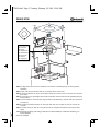
Zeichenerklärung
A:
Nur für Abzugsversion.
B:
Kerbe auf der Oberseite der Teleskopstruktur
kennzeichnet die Frontseite der Abzugshaube
(Bedienfeld rechts).
C:
Vorschriftsmäßiger Sitz der Anschlußdose der
Abzugshaube.
F:
Nur für Filterversion.
Das MAXIMAL ZULÄSSIGE Ausmaß der
Teleskopstruktur wird wie folgt berechnet:
a)
Distanz in mm von der Decke bis zum Kochfeld
vermessen;
b)
bei Kochfeldern mit Gas- oder gemischten
Kochstellen vom Meßwert 1000 mm abziehen bzw.
1100 mm bei Kochfeldern mit Elektroplatten;
c)
das Ergebnis gibt die maximale Abmessung an, auf
die die Teleskopstruktur eingestellt werden kann.
Key
A:
For extractor version only.
B:
Reference mark on the upper side of the telescopic
structure, indicating the front of the hood (control
panel on the right).
C:
Location for hood connection box.
F:
For filter version only.
How to calculate the MAXIMUM ALLOWED extension of
the telescopic structure (operation 1):
a)
measure the distance (in millimeters) from the ceiling
to the hob;
b)
subtract 1000 mm from this measurement for gas or
combination hobs; for electric hobs subtract 1100 mm;
c)
the measurment obtained is the MAXIMUM extension
of the telescopic structure.
Légende
A:
Uniquement pour version aspirante.
B:
Repère sur le dessus de la structure télescopique
indiquant la partie avant de la hotte (bandeau de
commande à droite).
C:
Logement prévu pour le boîtier de connexion de la
hotte.
F:
Uniquement pour version filtrante.
Comment calculer l’extension MAXIMUM AUTORISÉE
de la structure télescopique (opération 1) :
a)
mesurez la distance en millimètres entre le plafond et
le plan de cuisson ;
b)
ôtez 1000 mm (si le plan de cuisson est à gaz ou
mixte) ou 1100 mm (si le plan de cuisson est
électrique) ;
c)
la mesure obtenue représente l’extension MAXIMUM
selon laquelle vous pourrez régler la structure
télescopique.
Legenda
A:
Alleen voor de afzuigversie.
B:
Merkteken op de bovenzijde van de uitschuifbare
structuur, geeft de voorkant van de wasemkap aan
(bedieningspaneel rechts).
C:
Verplichte plaats van de verbindingsmof van de
wasemkap.
F:
Alleen voor de filterversie.
De MAXIMAAL TOEGESTANE lengte van de
uitschuifbare structuur berekenen (handeling 1) :
a)
meet de afstand in millimeters van het plafond tot de
kookplaat ;
b)
trek van deze maat 1000 mm af (als de kookplaat een
gas - of gemengd toestel is) of trek 1100 mm af (als de
kookplaat een elektrisch toestel is) ;
c)
de uitkomst geeft de MAXIMALE lengte weer waarop
de uitschuifbare structuur mag worden ingesteld.
Leyenda
A:
Sólo para el modelo aspirador.
B:
Marca de referencia en el lado superior de la
estructura telescópica que indica la parte frontal de la
campana (panel de control a la derecha).
C:
Lugar reservado exclusivamente para la caja de
conexión de la campana.
F:
Sólo para el modelo filtrante.
Cómo calcular la extensión MÁXIMA PERMITIDA de la
estructura telescópica (operación n° 1):
a)
medir la distancia en milímetros que hay desde el
techo hasta la encimera;
b)
restar a esta medida 1000 mm si se trata de una
encimera con quemadores a gas o mixtos y 1100 mm
para la encimera con quemadores eléctricos;
c)
el valor que se obtiene representa la extensión
MÁXIMA que puede tener la estructura telescópica.
Legenda
A:
Apenas na versão filtrante.
B:
Sinal de referência do lado superior da estrutura
telescópica, indica a parte frontal do exaustor (painel
de controlo à direita).
C:
Sede obrigatória da caixa de conexão do exaustor.
F:
Apenas na versão filtrante.
Como calcular a extensão MÁXIMA ADMITIDA da
estrutura telescópica (operação 1):
a)
meça a distância em milímetros do tecto à placa de
fogão;
b)
do resultado, subtraia 1000 mm (caso a placa de
fogão seja a gás ou mista) ou subtraia 1100 mm (para
as placas eléctricas);
c)
a medida resultante é a extensão MÁXIMA de
regulação da estrutura telescópica.
Legenda
A:
Solo per versione aspirante.
B:
Tacca di riferimento sul lato superiore della struttura
telescopica, indica la parte frontale della cappa
(pannello di controllo a destra).
C:
Sede obbligata della scatola connessione della cappa.
F:
Solo per versione filtrante.
Come calcolare la estensione MASSIMA PERMESSA
della struttura telescopica (operazione 1):
a)
misurare la distanza in millimetri dal soffitto al piano di
cottura;
b)
da tale misura sottrarre 1000 mm (nel caso il piano di
cottura sia con fuochi a gas o misti) oppure sottrarre
1100 mm (nel caso il piano di cottura sia con fuochi
elettrici);
c)
la misura risultante rappresenta l’estensione MASSIMA
a cui potrà essere regolata la struttura telescopica.
02.
$ ) . 2 ...!!)31"
% 0 ..3 !"12&0#!2"201 "
/ "/0$02 0!)" 2 .2 #. !! 3 2!..."
$0!1 */0
& # $!0&2/!.2 #&2 # 1*/01"2 # . !! 32!.
) ) . 2 .32!.!1.2 "
+".# 10202ü+ÿþüÿüþ02.12"
201 "/ "0!0.
D 02!1202.)12.110$ 12.) 2 ! 3&"2
030..0!.2 "
E .)2 0 ".#2) .3.!120 PP100!2&1 #
030..0!.2 "/.200120".0! #2"
PP100!2&1 #030..0!.2 "
/.2002!"0120"
F .)12.1 #! *20.2! 1&0*02ü+ÿþ
02.102 . !020.!#10202
201 /
D
GB
F
NL
E
P
I
GR
75093a.fm5 Page 2 Tuesday, February 29, 2000 12:06 PM

DKSM 3790
5019 100 75093/A
8
9
9
9
9
10A
1
1
1
2F
5F
6F
7F
11
3F
5F
4F
B
C
10A:
Ein Abgasrohr mit Ø 200 mm installieren und mit dem Verbindungsring der Abzugshaube
verbinden.
10A:
Supply a Ø 200 mm exhaust tube for connection to the hood collar.
10A :
Prévoyez également un tuyau d'évacuation Ø 200 mm et branchez-le à l’anneau de connexion
de la hotte.
10A:
Zorg ook voor een afvoerpijp Ø 200 mm die verbonden moet worden aan de verbindingsring van
de wasemkap.
10A:
Colocar asimismo un tubo de descarga de 200 mm de diámetro y unirlo al anillo de conexión de
la campana.
10A:
Providencie também um tubo de descarga de Ø 200 mm a coligar no anel de conexão do
exaustor.
10A:
Prevedere anche un tubo di scarico Ø 200 mm da collegare all’anello di connessione della
cappa.
$ $.202.1&."0&1 "ØPP #.1#/0002 /.2* 1*/01"2 #
.
!!
3
2
!
.
Nicht mitgeliefert
Not provided
Non fourni
Niet bijgeleverd
No suministrado
Não fornecido
Non fornito
û0.!$02.
75093a.fm5 Page 3 Tuesday, February 29, 2000 12:06 PM

5019 100 75093/A
DKSM 3790
12
12
13
14
14
14
14
16
16
14
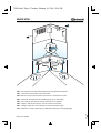
15A:
Das Abgasrohr mit dem Verbindungsring der Abzugshaube verbinden.
15A:
Connect the exhaust tube to the hood collar.
15A :
Branchez le tuyau d’évacuation à l’anneau de connexion de la hotte.
15A:
Verbind de afvoerpijp met de verbindingsring van de wasemkap.
15A:
Unir el tubo de descarga al anillo de conexión de la campana.
15A:
Coligue o tubo de descarga no anel de conexão do exaustor.
15A:
Collegare il tubo di scarico all’anello di connessione della cappa.
$ #/1202 1&.0&1"12 /.2* 1*/01"2 #. !! 32!.
75093a.fm5 Page 4 Tuesday, February 29, 2000 12:06 PM

5019 100 75093/A
DKSM 3790
1
5
6
2
b
b
b
3
6
4
Fig. 1
a
a
a
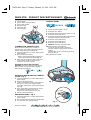
1.
Control panel.
2.
Grease filters (6 grease filters).
3.
Grease filter handle.
4.
Halogen lamps.
5.
Telescopic flue.
6.
Utensil hanger.
CLEANING THE GREASE FILTER
Wash the grease filters once a month, or
whenever the grease filter saturation indicator
flashes (Extraction speed indicator
2
).
1.
Unplug the appliance or switch off the mains
power supply.
2.
Remove the grease filters:
- pull the grease filter handles towards the
centre, then downwards (
a, b - Fig. 1
).
3.
After cleaning the grease filters remount in
reverse order, making sure the entire
extraction surface is covered.
Resetting the grease filter saturation
indicator:
press the extractor OFF button for
three seconds. The grease filter saturation
indicator will stop flashing.
FITTING OR REPLACING THE CARBON
FILTER - Fig. 2
1.
Unplug the appliance or switch off the mains
power supply.
2.
Remove the grease filters.
3.
Fit four carbon filters: fit the carbon filters at
the rear (
c -
next to the halogen lamps);
secure the carbon filters at the front using the
clips (
d
).
4.
If the carbon filters need renewing, remove
the old filters and fit four new ones.
Replace the carbon filters once a year.
5.
Remount the grease filters.
REPLACING LAMPS - Fig. 3
1.
Unplug the appliance or switch off the mains
power supply.
2.
Remove the burnt-out lamp from its fitting (
e
).
3.
Use only 20W max halogen lamps.
CONTROL PANEL
1.
Speed decrease button -
5
Ö
1
.
2.
Extraction OFF button.
3.
Extraction ON speed increase button -
0
Ö
5
.
4.
Extraction speed indicator
1
.
5.
Extraction speed indicator
2
and grease filter
saturation indicator (when flashing).
6.
Extraction speed indicator
3
.
7.
Extraction speed indicator
4
.
8.
Extraction speed indicator
5
.
9. Intensive
extraction speed indicator.
10.
Timer intensive speed button.
The hood operates at this speed for 5
minutes and then returns to the previous
settings.
This function can be cancelled by pressing
button
1
,
2
or
3
.
11.
Light ON-OFF switch.
1
2
3
45678 9
10 11
c
e
d
c
Fig. 2
Fig. 3
PRODUCT DESCRIPTION SHEET
F NL E PGBD GRI
75093a.fm5 Page 6 Tuesday, February 29, 2000 12:06 PM
-
 1
1
-
 2
2
-
 3
3
-
 4
4
-
 5
5


Bauknecht DKSM 3790/1 Program Chart
- Categoria
- Cappe da cucina
- Tipo
- Program Chart
in altre lingue
- English: Bauknecht DKSM 3790/1
- français: Bauknecht DKSM 3790/1
- español: Bauknecht DKSM 3790/1
- Deutsch: Bauknecht DKSM 3790/1
- Nederlands: Bauknecht DKSM 3790/1
- português: Bauknecht DKSM 3790/1