Olimpia Splendid B0969 Manuale utente
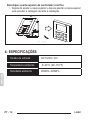
- Categoria
- Condizionatori d'aria a sistema split
- Tipo
- Manuale utente

USER MANUAL
EN
MANUEL DE L’UTILISATEUR
BETRIEBSANLEITUNG
FR
DE
MANUAL DE USO
ES
MANUAL DE USO
PT
GEBRUIKERSHANDLEIDING
NL
MANUALE D’USO
IT
Kit B0969
for LCAC


LCAC IT - 3
ITALIANO
Tutte le gure presenti in questo manuale sono solamente a titolo esplicativo.
Il telecomando in Vostro possesso potrebbe risultare differente da quello
mostrato. Operare in base al Vostro telecomando.
INDICE GENERALE
1- AVVERTENZE PER LA SICUREZZA .................................4
2- PREPARAZIONE ALL’INSTALLAZIONE ...........................5
3- METODO DI INSTALLAZIONE ...........................................6
4- DATI TECNICI ...................................................................12
5- CARATTERISTICHE E FUNZIONI DEL
COMANDO A MURO .........................................................13
6- DISPLAY LCD DEL COMANDO A MURO ........................ 14
7- PULSANTI SUL COMANDO A MURO..............................15
8- PREPARAZIONE AL FUNZIONAMENTO.........................16
9- FUNZIONAMENTO ...........................................................17
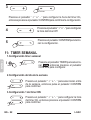
10- FUNZIONI TIMER .............................................................20
11- TIMER SETTIMANALE ....................................................22
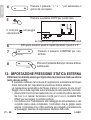
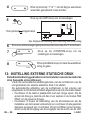
12- IMPOSTAZIONE PRESSIONE STATICA ESTERNA .......26
13- GESTIONE ALLARMI GUASTO ......................................28
14- REQUISITI ED INDICAZIONI TECNICHE ........................ 28

LCACIT - 4
ITALIANO
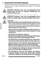
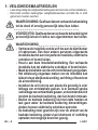
1- AVVERTENZE PER LA SICUREZZA
- Leggere le avvertenze per la sicurezza prima di installare l’unità.
- Le avvertenze indicate sotto sono importanti e devono essere sempre
rispettate.
AVVERTENZA: Indica un pericolo derivante da una
gestione non corretta dell’unità che potrebbe causare
infortuni gravi o persino la morte.
_ _ _ _ _ _ _ _ _ _ _ _ _ _ _ _ _ _ _ _ _ _ _ _ _ _ _ _ _ _
ATTENZIONE: Indica un pericolo derivante da una
gestione non corretta dell’unità che potrebbe causare
infortuni gravi o all’unità.
AVVERTENZA_ _ _ _ _ _ _ _ _ _ _ _ _ _ _ _ _ _ _ _ _ _ _ _
- Rivolgersi al distributore autorizzato o a profes-
sionisti per installare l’unità. L’installazione da
parte di persone non autorizzate potrebbe portare
ad un’installazione imperfetta, scosse elettriche o
incendi.
- Attenersi a questo manuale di installazione. Un’in-
stallazione incorretta potrebbe causare scosse
elettriche o incendi.
- Non disinstallare l’unità senza motivo.
- La disinstallazione senza motivo dell’unità potrebbe
causare un funzionamento anomalo, il riscaldamen-
to dell’aria condizionata o incendi.
- Non installare l’unità in un luogo soggetto alla
fuga di gas inammabili. La fuga di gas inamma-
bili nell’ambiente dove si trova il comando a muro
comporta il rischio di incendio.
- Non utilizzare l’apparecchio con le mani bagnate e
non lasciare che l’acqua entri nel telecomando. In
caso contrario, sussiste il rischio di scossa elettrica.
- Il cablaggio deve adattarsi alla corrente del tele-
comando. In caso contrario, sussiste il rischio di

LCAC IT - 5
ITALIANO
fughe di elettricità o calore e causare un incendio.
- I cavi indicati devono essere utilizzati per il cablag-
gio. Nessuna forza esterna deve essere applicata
al morsetto. Ciò potrebbe portare al taglio o il
riscaldamento del cavo, causando un incendio.
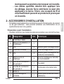
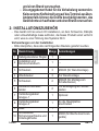
2- PREPARAZIONE ALL’INSTALLAZIONE
- Non installare in un luogo ricco di combustibile pesante, vapore o gas
solforici per evitare la deformazione del prodotto che porterebbe ad un
malfunzionamento del sistema.
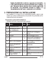
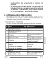
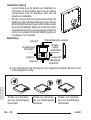
Preparazione prima dell’installazione
- Vericare che tutti i componenti siano presenti.
N. Nome Qtà. Note
1Comando a muro 1 - -
2Manuale per l’uso e
per l’installazione 1 - -
3Viti 3M4X20 (per montaggio a
muro)
4Tasselli 3Per montaggio a muro
5Viti 2M4X25 (per montaggio su
scatola di commutazione)
6Barre a vite di plastica 2Per ssaggio su scatola di
commutazione
7Cavi di collegamento,
gruppo-1 1Opzionale
8Cavi di collegamento,
gruppo-2 1Collegamento a scheda
madre
9Batteria 1 - -
10 Vite e rondella di bloc-
caggio lettanti 1M4X8 (Per lamiera dell’unità
interna)

LCAC
4
Applicable to KJR-120C1/TF-E only
Applicable to KJR-120C1/BTF-E only
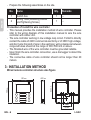
3. INSTALLATION METHOD
Fig 3-1
Fig 3-2(a)
Fig 3-2(b)
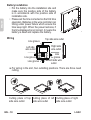
1.Wired remote controller structure size gure
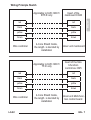
2.Wiring Principle Sketch:
red
black
yellow
brown
red
black
yellow
brown
Insert of the
mainboard CN40
Wire controller Indoor unit mainboard
4-Core Shield Cable, the length
is decided by installation
-----------------------------------
-----------------------------------
-----------------------------------
-----------------------------------
red
black
yellow
brown
red
black
yellow
brown
Insert of the Multi-function
control box CN5
Wire controller Indoor unit Multi-function control board
4-Core Shield Cable, the length
is decided by installation
-----------------------------------
-----------------------------------
-----------------------------------
-----------------------------------
120
122
18.5
83.5
46
62
4
Applicable to KJR-120C1/TF-E only
Applicable to KJR-120C1/BTF-E only
3. INSTALLATION METHOD
Fig 3-1
Fig 3-2(a)
Fig 3-2(b)
1.Wired remote controller structure size gure
2.Wiring Principle Sketch:
red
black
yellow
brown
red
black
yellow
brown
Insert of the
mainboard CN40
Wire controller Indoor unit mainboard
4-Core Shield Cable, the length
is decided by installation
-----------------------------------
-----------------------------------
-----------------------------------
-----------------------------------
red
black
yellow
brown
red
black
yellow
brown
Insert of the Multi-function
control box CN5
Wire controller Indoor unit Multi-function control board
4-Core Shield Cable, the length
is decided by installation
-----------------------------------
-----------------------------------
-----------------------------------
-----------------------------------
120
122
18.5
83.5
46
62
IT - 6
ITALIANO
- Preparare i seguenti insiemi nel luogo di installazione.
N. Nome Qtà. Note
1Scatola di commutazione 1 - -
2Tubo di collegamento (Manicotto
isolante e vite di serraggio) 1 - -
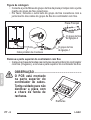
Precauzioni per l’installazione del comando a muro
- Questo manuale fornisce il metodo di installazione del comando a muro.
Fare riferimento allo schema elettrico di questo manuale di installazione
per cablare il comando a muro con l’unità interna.
-
Il comando a muro deve funzionare a circuito chiuso a bassa tensione. Evitare
di collegare direttamente il cavo da 220V o quello ad alto voltaggio di 380V, e
non connettere questo tipo di cavo nel circuito chiuso indicato sopra; lo spazio
libero del cablaggio tra il tubo deve essere incluso tra 300~500 mm o più
.
- Il cavo schermato del comando a muro deve essere collegato a terra in
maniera sicura.
- Al termine del collegamento del comando a muro, utilizzare un tester per
controllare l’isolamento.
- Il cavo di collegamento del comando a muro non deve essere più lungo
di 20 metri.
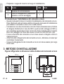
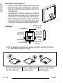
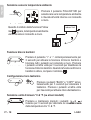
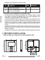
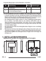
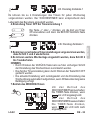
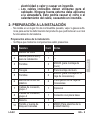
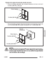
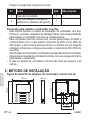
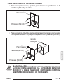
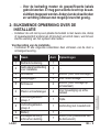
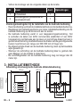
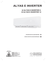
3- METODO DI INSTALLAZIONE
Figura rafgurante le dimensioni della struttura del comando a muro
120 mm120 mm
122 mm
18.5 mm
83.5 mm
46 mm
62 mm

LCAC IT - 7
ITALIANO
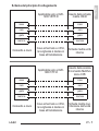
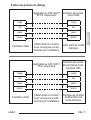
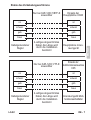
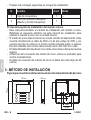
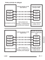
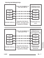
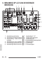
Schema del principio di collegamento
Applicabile solo a KJR-
120C1/BTF-E
Applicabile solo a KJR-
120C1/TF-E
Comando a muro
Comando a muro
Inserto della scheda
madre CN40
Inserto della scatola
di comando Multifun-
zione CN5
Scheda madre unità
interna
Scheda madre mul-
tifunzione dell’unità
interna
Cavo schermato a 4 Poli,
la lunghezza è decisa in
base all’installazione
Cavo schermato a 4 Poli,
la lunghezza è decisa in
base all’installazione
rosso
nero
giallo
marrone
rosso
nero
giallo
marrone
rosso
nero
giallo
marrone
rosso
nero
giallo
marrone

LCAC
5
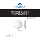
3. INSTALLATION METHOD
Fig 3-4
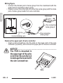
Connect the female joint of wires group from the mainboard with the male joint of
connective wires group. (See Fig.3-3)
Please connect the other side of connective wires group with the male joint of
wires group leads from wire controller. (See Fig.3-3)
Fig 3-3
Mainboard
4-core shielding wire
3.Wiring figure
4.Remove the upper part of wire controller
The connective wires group-1
The connective wires group-2
CN40
Insert a slot screwdriver into the slots in the lower
part of the wire controller (2 places), and remove
the upper part of the wire controller. (Fig.3-4)
Slots
NOTICE
The PCB is mounted in the upper part of the wire
controller. Be careful not to damage the board
with the slot screwdriver.
IT - 8
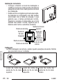
ITALIANO
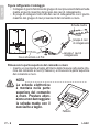
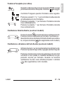
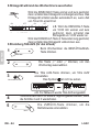
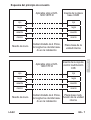
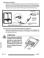
Figura rafgurante il cablaggio
• Collegare il giunto femmina del gruppo di cavi provenienti dalla scheda
madre al giunto maschio del gruppo dei cavi di collegamento.
• Si prega di collegare l’altro lato dei cavi di collegamento con il giunto
maschio del gruppo di cavi provenienti dal comando a muro.
Gruppo-2 cavi
di collegamento
Gruppo-1 cavi di
collegamento
Fessure
Cavo schermato a 4 Poli
CN40
Scheda madre
Rimuovere la parte superiore del comando a muro
• Inserire un cacciavite a taglio all’interno delle fessure nella parte infe-
riore del comando a muro (2 fessure), e rimuovere la parte superiore
del comando a muro.
NOTA _ _ _ _ _ _ _ _ _ _ _ _ _ _ _ _ _ _ _ _ _ _ _ _ _
La scheda elettronica
è montata nella parte
superiore del comando
a muro. Prestare atten-
zione a non danneggiare
la scheda madre con il
cacciavite a taglio.

LCAC
6
Fig 3-5
Fig 3-6
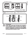
3. INSTALLATION METHOD
Switch box
Back plate
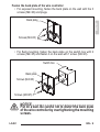
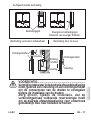
For exposed mounting, fasten the back plate on the wall with the 3 screws (M4×20)
and plugs. (Fig.3-5)
For ush-mounting, fasten the back plate on the switch box with 2 screws (M4×25) and
fasten it on the wall with 1 screw (M4×20). (Fig.3-6)
5. Fasten the back plate of the wire controller
Back plate
Screws (M4×20)
Screw (M4×20)
Screws (M4×25)
NOTICE
Put on a at surface. Be careful not to distort the back plate of the wire controller
by overtightening the mounting screws.
6
Fig 3-5
Fig 3-6
3. INSTALLATION METHOD
Switch box
Back plate
For exposed mounting, fasten the back plate on the wall with the 3 screws (M4×20)
and plugs. (Fig.3-5)
For ush-mounting, fasten the back plate on the switch box with 2 screws (M4×25) and
fasten it on the wall with 1 screw (M4×20). (Fig.3-6)
5. Fasten the back plate of the wire controller
Back plate
Screws (M4×20)
Screw (M4×20)
Screws (M4×25)
NOTICE
Put on a at surface. Be careful not to distort the back plate of the wire controller
by overtightening the mounting screws.
IT - 9
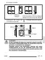
ITALIANO
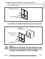
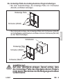
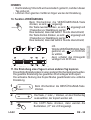
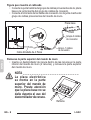
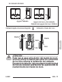
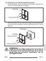
Piastra posteriore
Viti (M4×20)
Viti (M4×25)
Viti (M4×20)
Piastra posteriore
Scatola di
commutazione
Fissaggio della piastra posteriore del comando a muro
• Per il montaggio a vista, ssare la piastra posteriore sul muro con le
3 viti (M4×20) e tasselli.
• Per montaggio a lo, ssare la piastra posteriore sulla scatola di com-
mutazione con 2 viti (M4×25) e ssarlo sul muro con 1 vite (M4×20).
NOTA _ _ _ _ _ _ _ _ _ _ _ _ _ _ _ _ _ _ _ _ _ _ _ _ _
Posizionare su una parete. Prestare attenzione a non
deformare la piastra posteriore del comando a muro
serrando eccessivamente le viti di montaggio.

LCAC
7
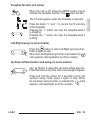
Put the battery into the installationsite and make sure the positive side of the battery
is in accordance with the positive side of installationsite.(See Fig.3-7)
Please set the time corrected on the rst time operation. Batteries in the wire
controller can timing under power failure which ensure the time keep right. When
the power restores, if the time displayed is not correct, it means the battery is dead
and replace the battery.
Fig 3-7
3. INSTALLATION METHOD
6. Battery installation
8
Fig 3-8
Fig 3-9 Fig 3-10
3. INSTALLATION METHOD
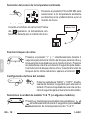
7. Wiring
Cutting place of top
side wire outlet
Cutting place of left
side wire outlet
Cutting place of right
side wire outlet
A. For wiring in the slot, four outletting positions.
There are three need cutting.
Diameter of wall hole:Φ20mm
Embedded switch
box wiring
B.Shielded wiring
Wiring
hole
Wiring through the wall
Wall hole and wiring hole
Putty
Putty
Putty
Trap
Trap
Trap
CAUTION
Avoid the water enter into the wired remote controller, use trap and putty to seal the
connectors of wires during wiring installation. (Fig.3-10)
When under installation, reserve certain length of the connecting wire for convenient
to take down the wired remote controller while during maintenance.
Top side
wire outlet
Left side
wire outlet
Right side
wire outlet
Bottom side
wire outlet
Line groove
Line groove
Line groove
Line groove
8
Fig 3-8
Fig 3-9 Fig 3-10
3. INSTALLATION METHOD
7. Wiring
Cutting place of top
side wire outlet
Cutting place of left
side wire outlet
Cutting place of right
side wire outlet
A. For wiring in the slot, four outletting positions.
There are three need cutting.
Diameter of wall hole:Φ20mm
Embedded switch
box wiring
B.Shielded wiring
Wiring
hole
Wiring through the wall
Wall hole and wiring hole
Putty
Putty
Putty
Trap
Trap
Trap
CAUTION
Avoid the water enter into the wired remote controller, use trap and putty to seal the
connectors of wires during wiring installation. (Fig.3-10)
When under installation, reserve certain length of the connecting wire for convenient
to take down the wired remote controller while during maintenance.
Top side
wire outlet
Left side
wire outlet
Right side
wire outlet
Bottom side
wire outlet
Line groove
Line groove
Line groove
Line groove
IT - 10
ITALIANO
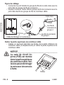
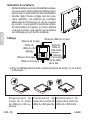
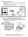
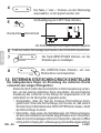
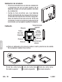
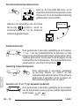
Installazione della batteria
• Posizionare la batteria nel sito di installazione
ed assicurarsi che il lato positivo della bat-
teria sia conforme al lato positivo del sito di
installazione.
• Correggere l’ora al primo utilizzo. Le batterie
all’interno del comando a muro continuano a
funzionare in caso di interruzione di corrente,
assicurando di mantenere l’orario corretto. Se
l’ora mostrata non è corretta al ripristino della
corrente,è necessario sostituire la batteria.
Cablaggio
Scanalatura
Scanalatura
Scanalatura
Scanala-
tura
Presa lo lato
inferiore
Presa lo lato
superiore
Presa lo
lato destro
a. Per il cablaggio nella fessura esistono quattro posizioni di uscita.
E’ necessario eseguire tre tagli.
Punto di taglio presa
lo lato superiore Punto di taglio presa
lo lato sinistro Punto di taglio presa
lo lato
destro
Presa lo
lato sinistro

LCAC
8
Fig 3-8
Fig 3-9 Fig 3-10
3. INSTALLATION METHOD
7. Wiring
Cutting place of top
side wire outlet
Cutting place of left
side wire outlet
Cutting place of right
side wire outlet
A. For wiring in the slot, four outletting positions.
There are three need cutting.
Diameter of wall hole:Φ20mm
Embedded switch
box wiring
B.Shielded wiring
Wiring
hole
Wiring through the wall
Wall hole and wiring hole
Putty
Putty
Putty
Trap
Trap
Trap
CAUTION
Avoid the water enter into the wired remote controller, use trap and putty to seal the
connectors of wires during wiring installation. (Fig.3-10)
When under installation, reserve certain length of the connecting wire for convenient
to take down the wired remote controller while during maintenance.
Top side
wire outlet
Left side
wire outlet
Right side
wire outlet
Bottom side
wire outlet
Line groove
Line groove
Line groove
Line groove
IT - 11
ITALIANO
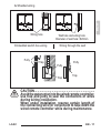
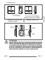
b. Cablaggio schermato
Foro cablaggio Foro del muro e foro del cablaggio
Diametro del foro del muro: Φ20mm
Cablaggio scatola di commutazione
integrata
Cablaggio attraverso il muro
Stucco Stucco
Stucco
Sifone
Sifone
Sifone
ATTENZIONE _ _ _ _ _ _ _ _ _ _ _ _ _ _ _ _ _ _ _ _ _ _ _ _ _
Evitare che l’acqua entri all’interno del comando a
muro, utilizzare il sifone e lo stucco per sigillare i
connettori dei li durante l’installazione del cablaggio.
Durante l’installazione, lasciare una certa lunghezza
del lo di collegamento per facilitare le operazioni di
manutenzione del comando a muro.

LCAC
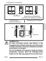
9
Fig 3-11
3. INSTALLATION METHOD
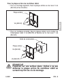
All the pictures in this manual are for explanation purpose only.
Your wire controller may be slightly dierent .The actual shape shall prevail.
8.Reattach the upper part of the wire controller
After adjusting the upper case and then buckle the upper case; avoid clamping the
wiring during installation. (
Fig 3-1
1)
IT - 12
ITALIANO
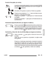
Ricollegare la parte superiore del comando a muro
• Dopo aver regolato e quindi serrato la copertura superiore; evitare di
stringere il cablaggio durante l’installazione.
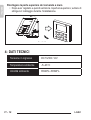
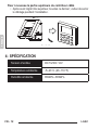
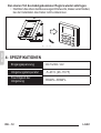
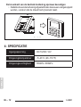
4- DATI TECNICI
Tensione in ingresso DC 5V/DC 12V
Temperatura ambiente -5~43°C
Umidità ambiente RH40%~RH90%

LCAC
11
POWER
MODE FAN SPEED
TIMER SWING SWING FOLLOW ME
DELAY/DAY OFF CONFIRM BACK COPY
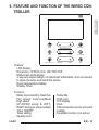
5. FEATURE AND FUNCTION OF THE WIRED
CONTROLLER
Function:
Mode: choose Auto-Cool-Dry- Heat -Fan
Fan speed: Auto/Low/Med/High speed
UP-DOWN swing & LEFT-RIGHT swing(on
some models)
Timer ON/OFF
Temp setting
Weekly timer
Follow Me
Child Lock
LCD display
Clock
Infrared remote receiver (on some models)
Faceplate function (on some models)
Feature:
LCD display.
Room temperature display.
Weekly Timer.
4-way wire layout design, no raised part
at backside, more convenient to place
the wires and install the device.
Malfunction code display: it can display
the error code, helpful for service.
Dimension:
H×W×D(mm) 122×120×18.5
IT - 13
ITALIANO
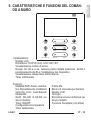
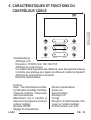
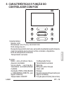
5- CARATTERISTICHE E FUNZIONI DEL COMAN-
DO A MURO
Caratteristiche:
Display LCD.
Dimensioni: H×W×D (mm) 122×120×18.5
Visualizzazione codice di errore.
Design con lo a 4 vie, nessuna parte rialzata posteriore, facilita il
posizionamento dei li e l’installazione del dispositivo.
Visualizzazione temperature dell’ambiente.
Timer settimanale.
Funzioni:
Modalità: Raffr.-Deum.-Automa-
tico- Riscaldamento -Ventilatore
Velocità vent: Auto/Bassa/
Media/Alta
Oscill. SU-GIÙ & SX-DX (su
alcuni modelli)
Timer ON/OFF
Congurazione temperatura
Timer settimanale
Follow Me
Blocco di sicurezza per bambini
Display LCD
Orologio
Ricevitore remoto a infrarossi (su
alcuni modelli)
Funzione Faceplate (non attiva)

LCAC
12
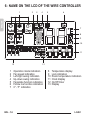
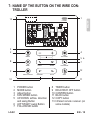
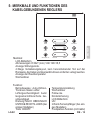
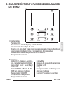
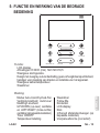
6. NAME ON THE LCD OF THE WIRE CONTROLER
1 Operation mode indication
2 Fan speed indication
3 Left-right swing indication
4 Up-down swing indication
5 Faceplate function indication
6 Follow me function indication
7 C° / F° indication
1 2 3 4 5 6
7
8
9
10
11
13 12
8 Temperature display
9 Lock indication
10 Room temperature indication
11 Clock display
12 On/O timer
13 Timer display
IT - 14
ITALIANO
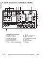
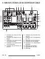
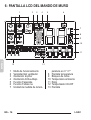
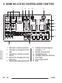
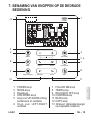
6- DISPLAY LCD DEL COMANDO A MURO
1 Modalità di funzionamento
2 Velocità ventilatore
3 Oscillazione Sx-Dx
4 Oscillazione Su-Giù
5 Funzione Faceplate
6 Funzione Follow me
7 Unità di misura temperatura
C° / F°
8 Display temperatura
9 Blocco bambini
10 Temperatura ambiente
11 Orologio
12 Timer On/Off
13 Display

LCAC
13
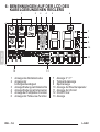
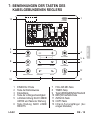
7. NAME OF THE BUTTON ON THE WIRE CONTROLER
1
2
3
4
5 6
7
8
9
10 11
12
POWER
MODE FAN SPEED
TIMER SWING SWING FOLLOW ME
DELAY/DAY OFF CONFIRM BACK COPY
13
IT - 15
ITALIANO
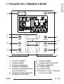
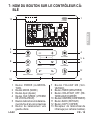
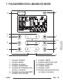
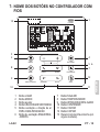
7- PULSANTI SUL COMANDO A MURO
1 Pulsante POWER
2 Pulsante MODE
3 Pulsante regolazione
4 Pulsante FAN SPEED
5 Pulsante UP-DOWN direzione
aria ed oscillazione
6 Pulsante oscillazione SX-DX
7 Pulsante FOLLOW ME
8 Pulsante TIMER
9 Pulsante DELAY/DAY OFF
10 Pulsante CONFIRM
11 Pulsante BACK
12 Pulsante COPY
13 Ricevitore remoto infrarossi
(su alcuni modelli)

LCAC
15
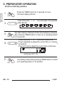
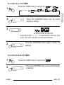
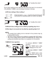
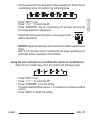
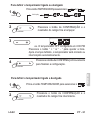
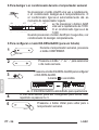
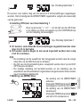
8. PREPARATORY OPERATION
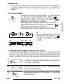
Press the TIMER button for 3 seconds or more.
The timer display will ash.
Press the button “+” or “-” to set the current time.
Press repeatedly to adjust the current time in 1-minute increments.
Press and hold to adjust the current time continuous.
ex.Monday AM 11:20
1
2
3
4
5
Press the button “ + ” or “ - ” to set the date. The selected
date will ash.
The date setting is nished and the time setting is prepared after pressing
TIMER button or there is no pressing button in 10 seconds.
The setting is done after pressing TIMER button or there is no
pressing button in 10 seconds.
Set the current day and time
TIMER
TIMER
TIMER
IT - 16
ITALIANO
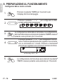
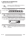
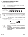
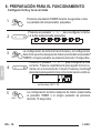
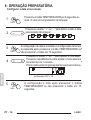
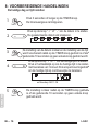
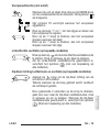
8- PREPARAZIONE AL FUNZIONAMENTO
Congurare data e orario corrente
Premere il pulsante TIMER per 3 secondi o più.
Il display del timer lampeggia.
Premere il pulsante “ + ” o “ - ” per congurare la data.
La data selezionata lampeggia.
La congurazione della data è terminata e la congurazione
dell’ora si attiva dopo aver premuto il pulsante TIMER o nessun
pulsante viene premuto per 10 secondi.
Premere il pulsante “ + ” o “ - ” per congurare l’ora cor-
rente. Premere ripetutamente per regolare l’ora corrente
con un incremento di 1 minuto. Premere e mantenere
premuto per regolare l’ora corrente in maniera continua.
La congurazione termina dopo aver premuto il pulsante
TIMER o nessun pulsante viene premuto per 10 secondi.

LCAC
16
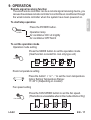
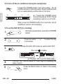
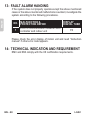
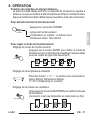
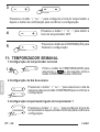
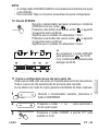
9. OPERATION
To start/stop operation
Press the POWER button.
Operation lamp
Air conditioner ON :Lit brightly
Air conditioner OFF:Not lit
To set the operation mode
Press the MODE button to set the operation mode.
(Heat function is invalid for cool only type unit)
Room temperature setting
Press the button“ + ”or “ - ” to set the room temperature.
Indoor Setting Temperature Range :
17~30℃(62~86℉/62~88℉(Depending on models)).
Lower Raise
Operation mode setting
POWER
MODE
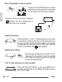
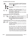
Remote signal receiving function
The wired remote controller can be a remote signal receiving device, you can use the
wireless remote controller to control the air-conditioner through the wired remote
controller when the system have been powered on.
16
9. OPERATION
To start/stop operation
Press the POWER button.
Operation lamp
Air conditioner ON :Lit brightly
Air conditioner OFF:Not lit
To set the operation mode
Press the MODE button to set the operation mode.
(Heat function is invalid for cool only type unit)
Room temperature setting
Press the button“ + ”or “ - ” to set the room temperature.
Indoor Setting Temperature Range :
17~30℃(62~86℉/62~88℉(Depending on models)).
Lower Raise
Operation mode setting
POWER
MODE
Remote signal receiving function
The wired remote controller can be a remote signal receiving device, you can use the
wireless remote controller to control the air-conditioner through the wired remote
controller when the system have been powered on.
17
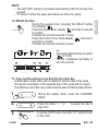
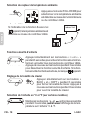
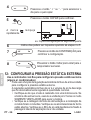
9. OPERATION
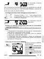
Fan speed setting
Press the FAN SPEED button to set the fan speed.
(This button is unavailable when in the mode of Auto or Dry)
Room temperature sensor selection
Indoor Unit
Press the FOLLOW ME button to select whether
the room temperature is detected at the indoor
unit or the wire controller.
When the Follow me function indication appears,
the room temperature is detected at the wire controller.
FAN SPEED
FOLLOW ME
IT - 17
ITALIANO
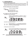
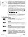
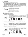
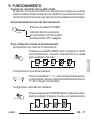
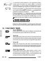
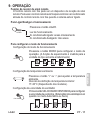
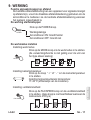
9- FUNZIONAMENTO
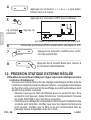
Funzione ricezione segnale remoto
Il comando a muro può funzionare come dispositivo di ricezione di un segnale
remoto, è possibile utilizzare il comando a muro wireless per controllare il con-
dizionatore tramite il comando a muro cablato quando il sistema è alimentato
.
Attivazione/disattivazione del funzionamento
Premere il pulsante POWER.
Spia funzionamento
Condizionatore ON: Accesa
Condizionatore OFF: Spenta
Per congurare il modo di funzionamento
Impostazione modo funzionamento
Premere il pulsante MODE per configurare il modo di
funzionamento. (Funzione riscaldamento non valida per
unità solo raffr.)
Impostazione temperatura ambiente
Premere il pulsante “ + ” o “ - ” per impostare la temperatura
dell’ambiente. Range configurazione temperatura interna:
17~30°C (A seconda dei modelli).
Configurazione velocità ventilatore
Premere il pulsante FAN SPEED per configurare la velocità
del ventilatore. (Pulsante non attivo in modalità Auto o Dry)

LCAC
17
9. OPERATION
Fan speed setting
Press the FAN SPEED button to set the fan speed.
(This button is unavailable when in the mode of Auto or Dry)
Room temperature sensor selection
Indoor Unit
Press the FOLLOW ME button to select whether
the room temperature is detected at the indoor
unit or the wire controller.
When the Follow me function indication appears,
the room temperature is detected at the wire controller.
FAN SPEED
FOLLOW ME
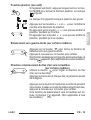
18
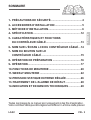
9. OPERATION
Child lock function
Press the button “+” and “-” simultaneously for 3 seconds to activate
the child lock function and lock all buttons on the wire controller.
Press the buttons again for 3 seconds to deactivate the child lock function.
When the child lock function is activated,the mark appears.
keypad tone setting
Press the button “BACK” and “COPY” simultaneously for 3 seconds to
close the keypad tone.
Press the buttons again for 3 seconds to open the keypad tone.
BACK COPY
°C & °F scale selection (on some models)
Press and hold and buttons together
for 3 seconds will alternate the temperature display
between the
℃&℉
scale.
SWING SWING
18
9. OPERATION
Child lock function
Press the button “+” and “-” simultaneously for 3 seconds to activate
the child lock function and lock all buttons on the wire controller.
Press the buttons again for 3 seconds to deactivate the child lock function.
When the child lock function is activated,the mark appears.
keypad tone setting
Press the button “BACK” and “COPY” simultaneously for 3 seconds to
close the keypad tone.
Press the buttons again for 3 seconds to open the keypad tone.
BACK
COPY
°C & °F scale selection (on some models)
Press and hold and buttons together
for 3 seconds will alternate the temperature display
between the
℃&℉
scale.
SWING SWING
18
9. OPERATION
Child lock function
Press the button “+” and “-” simultaneously for 3 seconds to activate
the child lock function and lock all buttons on the wire controller.
Press the buttons again for 3 seconds to deactivate the child lock function.
When the child lock function is activated,the mark appears.
keypad tone setting
Press the button “BACK” and “COPY” simultaneously for 3 seconds to
close the keypad tone.
Press the buttons again for 3 seconds to open the keypad tone.
BACK COPY
°C & °F scale selection (on some models)
Press and hold and buttons together
for 3 seconds will alternate the temperature display
between the
℃&℉
scale.
SWING SWING
18
9. OPERATION
Child lock function
Press the button “+” and “-” simultaneously for 3 seconds to activate
the child lock function and lock all buttons on the wire controller.
Press the buttons again for 3 seconds to deactivate the child lock function.
When the child lock function is activated,the mark appears.
keypad tone setting
Press the button “BACK” and “COPY” simultaneously for 3 seconds to
close the keypad tone.
Press the buttons again for 3 seconds to open the keypad tone.
BACK
COPY
°C & °F scale selection (on some models)
Press and hold and buttons together
for 3 seconds will alternate the temperature display
between the
℃&℉
scale.
SWING SWING
IT - 18
ITALIANO
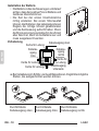
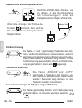
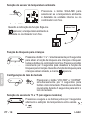
Selezione sensore temperatura ambiente
Premere il pulsante FOLLOW ME per
selezionare se la temperature ambiente
è rilevata all’unità interna o al comando
a muro.
Quando il simbolo della funzione Follow
me
17
9. OPERATION
Fan speed setting
Press the FAN SPEED button to set the fan speed.
(This button is unavailable when in the mode of Auto or Dry)
Room temperature sensor selection
Indoor Unit
Press the FOLLOW ME button to select whether
the room temperature is detected at the indoor
unit or the wire controller.
When the Follow me function indication appears,
the room temperature is detected at the wire controller.
FAN SPEED
FOLLOW ME
appare, la temperatura ambiente
viene rilevata al comando a muro.
Funzione blocco bambini
Premere il pulsante “+” e “-” contemporaneamente per
3 secondi per attivare la funzione di blocco bambini e
bloccare tutti i pulsanti sul comando a muro. Premere
i pulsanti un’altra volta per 3 secondi per disattivare la
funzione di blocco bambini. Quando la funzione di blocco
bambini è attiva, compare il simbolo
18
9. OPERATION
Child lock function
Press the button “+” and “-” simultaneously for 3 seconds to activate
the child lock function and lock all buttons on the wire controller.
Press the buttons again for 3 seconds to deactivate the child lock function.
When the child lock function is activated,the mark appears.
keypad tone setting
Press the button “BACK” and “COPY” simultaneously for 3 seconds to
close the keypad tone.
Press the buttons again for 3 seconds to open the keypad tone.
BACK COPY
°C & °F scale selection (on some models)
Press and hold and buttons together
for 3 seconds will alternate the temperature display
between the
℃&℉
scale.
SWING SWING
.
Congurazione tono tastierino
Premere i pulsanti “BACK” e “COPY” simul-
taneamente per 3 secondi per silenziare il
tastierino. Premere i pulsanti un’altra volta
per 3 secondi per attivare il tono del tastierino.
Selezione unità di misura °C & °F (su alcuni modelli)
Premere e mantenere premuti i pulsanti
18
9. OPERATION
Child lock function
Press the button “+” and “-” simultaneously for 3 seconds to activate
the child lock function and lock all buttons on the wire controller.
Press the buttons again for 3 seconds to deactivate the child lock function.
When the child lock function is activated,the mark appears.
keypad tone setting
Press the button “BACK” and “COPY” simultaneously for 3 seconds to
close the keypad tone.
Press the buttons again for 3 seconds to open the keypad tone.
BACK COPY
°C & °F scale selection (on some models)
Press and hold and buttons together
for 3 seconds will alternate the temperature display
between the
℃&℉
scale.
SWING SWING
&
18
9. OPERATION
Child lock function
Press the button “+” and “-” simultaneously for 3 seconds to activate
the child lock function and lock all buttons on the wire controller.
Press the buttons again for 3 seconds to deactivate the child lock function.
When the child lock function is activated,the mark appears.
keypad tone setting
Press the button “BACK” and “COPY” simultaneously for 3 seconds to
close the keypad tone.
Press the buttons again for 3 seconds to open the keypad tone.
BACK COPY
°C & °F scale selection (on some models)
Press and hold and buttons together
for 3 seconds will alternate the temperature display
between the
℃&℉
scale.
SWING SWING
insieme per 3 secondi per alternare la visualizzazione
della temperatura tra °C & °F.

LCAC
19
9. OPERATION
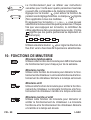
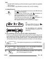
Faceplate function (on some models)
1.When the unit is o,Press the MODE button long to activate the faceplate
function.The mark will ash.
2. Press the button “+” and “-” to control the lift and drop of the faceplate.
Pressing the “+” button can stop the faceplate,while it is dropping.
Pressing the “-” button can stop the faceplate,while it is lifting.
The F2 mark appears when
the faceplate is adjusted.
MODE
Left-Right swing (on some models)
Press the button to start Left-Right swing function.
Press it again to stop.
When the Left-Right swing function is activated, the mark appears.(Not
applicable to all the models)
SWINGSWING
20
9. OPERATION
Up-Down airflow direction and swing (on some models)
1.Press the button every time, the louver swings 6 degrees.
2.Press and hold the button for 2 seconds,it turns into up-down swing mode,
press ti again to stop.
When the Up-Down swing function is activated,the mark appears. (Not applicable
to all the models)
The operation can refer to the following instructions for the unit with four Up-Down
louvers can be operated individually.
-0 -1 -2 -3 -4
1.Press the button to activate the Up-Down adjusting
louver function.
The mark will ash.(Not applicable to all the models)
2.Pressing the button “+” or“-” can select the movement
of four louvers.Each time you push the button,the wire
controller select in a sequence that goes from:(the icon
means the four louvers move at the same time.)
3. And then use button to adjust the Up-Down airow direction of the selected
louver.
-0
SWING SWING
SWING SWING
Use button to adjust the Up-down airow direction.
19
9. OPERATION
Faceplate function (on some models)
1.When the unit is o,Press the MODE button long to activate the faceplate
function.The mark will ash.
2. Press the button “+” and “-” to control the lift and drop of the faceplate.
Pressing the “+” button can stop the faceplate,while it is dropping.
Pressing the “-” button can stop the faceplate,while it is lifting.
The F2 mark appears when
the faceplate is adjusted.
MODE
Left-Right swing (on some models)
Press the button to start Left-Right swing function.
Press it again to stop.
When the Left-Right swing function is activated, the mark appears.(Not
applicable to all the models)
SWINGSWING
16
9. OPERATION
To start/stop operation
Press the POWER button.
Operation lamp
Air conditioner ON :Lit brightly
Air conditioner OFF:Not lit
To set the operation mode
Press the MODE button to set the operation mode.
(Heat function is invalid for cool only type unit)
Room temperature setting
Press the button“ + ”or “ - ” to set the room temperature.
Indoor Setting Temperature Range :
17~30℃(62~86℉/62~88℉(Depending on models)).
Lower Raise
Operation mode setting
POWER
MODE
Remote signal receiving function
The wired remote controller can be a remote signal receiving device, you can use the
wireless remote controller to control the air-conditioner through the wired remote
controller when the system have been powered on.
IT - 19
ITALIANO
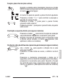
Funzione Faceplate (non attiva)
Quando l’unità è spenta; premere il pulsante MODE a lungo
per attivare la funzione Faceplate. Il simbolo
19
9. OPERATION
Faceplate function (on some models)
1.When the unit is o,Press the MODE button long to activate the faceplate
function.The mark will ash.
2. Press the button “+” and “-” to control the lift and drop of the faceplate.
Pressing the “+” button can stop the faceplate,while it is dropping.
Pressing the “-” button can stop the faceplate,while it is lifting.
The F2 mark appears when
the faceplate is adjusted.
MODE
Left-Right swing (on some models)
Press the button to start Left-Right swing function.
Press it again to stop.
When the Left-Right swing function is activated, the mark appears.(Not
applicable to all the models)
SWINGSWING
lampeggia
.
Il simbolo F2 appare quando il frontalino viene regolato.
Premere i pulsanti “+” e “-” per controllare il sollevamento
ed abbassamento del frontalino.
Premere il pulsante “+” per fermare il frontalino durante
il suo abbassamento.
Premere il pulsante “-” per fermare il frontalino durante
il suo sollevamento.
Oscillazione Sinistra-Destra (su alcuni modelli)
Premere il pulsante
18
9. OPERATION
Child lock function
Press the button “+” and “-” simultaneously for 3 seconds to activate
the child lock function and lock all buttons on the wire controller.
Press the buttons again for 3 seconds to deactivate the child lock function.
When the child lock function is activated,the mark appears.
keypad tone setting
Press the button “BACK” and “COPY” simultaneously for 3 seconds to
close the keypad tone.
Press the buttons again for 3 seconds to open the keypad tone.
BACK COPY
°C & °F scale selection (on some models)
Press and hold and buttons together
for 3 seconds will alternate the temperature display
between the
℃&℉
scale.
SWING SWING
per iniziare la funzione oscillazione Sx-Dx
.
Premere ancora il pulsante per fermare l’oscillazione.
Quando la funzione oscillazione Sinistra-Destra viene attiva-
ta, compare il simbolo
18
9. OPERATION
Child lock function
Press the button “+” and “-” simultaneously for 3 seconds to activate
the child lock function and lock all buttons on the wire controller.
Press the buttons again for 3 seconds to deactivate the child lock function.
When the child lock function is activated,the mark appears.
keypad tone setting
Press the button “BACK” and “COPY” simultaneously for 3 seconds to
close the keypad tone.
Press the buttons again for 3 seconds to open the keypad tone.
BACK COPY
°C & °F scale selection (on some models)
Press and hold and buttons together
for 3 seconds will alternate the temperature display
between the
℃&℉
scale.
SWING SWING
.(Non applicabile a tutti i modelli).
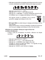
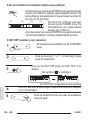
Oscillazione e direzione dell’aria Su-Giù (su alcuni modelli)
Utilizzare il pulsante
18
9. OPERATION
Child lock function
Press the button “+” and “-” simultaneously for 3 seconds to activate
the child lock function and lock all buttons on the wire controller.
Press the buttons again for 3 seconds to deactivate the child lock function.
When the child lock function is activated,the mark appears.
keypad tone setting
Press the button “BACK” and “COPY” simultaneously for 3 seconds to
close the keypad tone.
Press the buttons again for 3 seconds to open the keypad tone.
BACK COPY
°C & °F scale selection (on some models)
Press and hold and buttons together
for 3 seconds will alternate the temperature display
between the
℃&℉
scale.
SWING SWING
per regolare la direzione dell’aria Su-Giù
.
Premere il pulsante ogni volta, la griglia oscilla di 6 gradi.
Premere e mantenere premuto il pulsante per 2 secondi,il
comando a muro passa in modalità oscillazione su-giù,
premerlo ancora per fermarlo. Quando la funzione
oscillazione Su-Giù viene attivata,compare il simbolo
18
9. OPERATION
Child lock function
Press the button “+” and “-” simultaneously for 3 seconds to activate
the child lock function and lock all buttons on the wire controller.
Press the buttons again for 3 seconds to deactivate the child lock function.
When the child lock function is activated,the mark appears.
keypad tone setting
Press the button “BACK” and “COPY” simultaneously for 3 seconds to
close the keypad tone.
Press the buttons again for 3 seconds to open the keypad tone.
BACK COPY
°C & °F scale selection (on some models)
Press and hold and buttons together
for 3 seconds will alternate the temperature display
between the
℃&℉
scale.
SWING SWING
. (Non applicabile a tutti i modelli)

LCAC
20
9. OPERATION
Up-Down airflow direction and swing (on some models)
1.Press the button every time, the louver swings 6 degrees.
2.Press and hold the button for 2 seconds,it turns into up-down swing mode,
press ti again to stop.
When the Up-Down swing function is activated,the mark appears. (Not applicable
to all the models)
The operation can refer to the following instructions for the unit with four Up-Down
louvers can be operated individually.
-0 -1 -2 -3 -4
1.Press the button to activate the Up-Down adjusting
louver function.
The mark will ash.(Not applicable to all the models)
2.Pressing the button “+” or“-” can select the movement
of four louvers.Each time you push the button,the wire
controller select in a sequence that goes from:(the icon
means the four louvers move at the same time.)
3. And then use button to adjust the Up-Down airow direction of the selected
louver.
-0
SWING SWING
SWING SWING
Use button to adjust the Up-down airow direction.
16
9. OPERATION
To start/stop operation
Press the POWER button.
Operation lamp
Air conditioner ON :Lit brightly
Air conditioner OFF:Not lit
To set the operation mode
Press the MODE button to set the operation mode.
(Heat function is invalid for cool only type unit)
Room temperature setting
Press the button“ + ”or “ - ” to set the room temperature.
Indoor Setting Temperature Range :
17~30℃(62~86℉/62~88℉(Depending on models)).
Lower Raise
Operation mode setting
POWER
MODE
Remote signal receiving function
The wired remote controller can be a remote signal receiving device, you can use the
wireless remote controller to control the air-conditioner through the wired remote
controller when the system have been powered on.
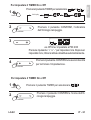
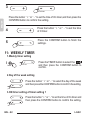
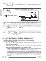
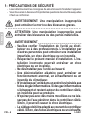
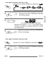
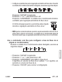
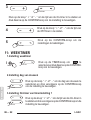
21
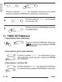
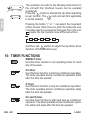
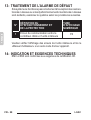
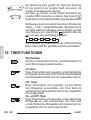
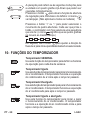
10. TIMER FUNCTIONS
WEEKLY timer
Use this timer function to set operating times for each day of the week.
On timer
Use this timer function to start air conditioner operation.The timer operates
and air conditioner operation starts after the time has passed.
O timer
Use this timer function to stop air conditioner operation.The timer operates
and air conditioner operation stops after the time has passed.
On and O timer
Use this timer function to start and stop air conditioner operation.The timer
operates and air conditioner operation starts and stops after the time has
passed.
21
10. TIMER FUNCTIONS
WEEKLY timer
Use this timer function to set operating times for each day of the week.
On timer
Use this timer function to start air conditioner operation.The timer operates
and air conditioner operation starts after the time has passed.
O timer
Use this timer function to stop air conditioner operation.The timer operates
and air conditioner operation stops after the time has passed.
On and O timer
Use this timer function to start and stop air conditioner operation.The timer
operates and air conditioner operation starts and stops after the time has
passed.
IT - 20
ITALIANO
L’operazione può fare riferimento alle seguenti istruzioni
per l’unità con quattro griglie. La funzione Su-Giù può
essere utilizzata individualmente anche per gli apparecchi
che supportano l’unità a 4 griglie.
Premere il pulsante
18
9. OPERATION
Child lock function
Press the button “+” and “-” simultaneously for 3 seconds to activate
the child lock function and lock all buttons on the wire controller.
Press the buttons again for 3 seconds to deactivate the child lock function.
When the child lock function is activated,the mark appears.
keypad tone setting
Press the button “BACK” and “COPY” simultaneously for 3 seconds to
close the keypad tone.
Press the buttons again for 3 seconds to open the keypad tone.
BACK COPY
°C & °F scale selection (on some models)
Press and hold and buttons together
for 3 seconds will alternate the temperature display
between the
℃&℉
scale.
SWING SWING
per attivare la funzione di rego-
lazione della griglia Su-Giù. Il simbolo
18
9. OPERATION
Child lock function
Press the button “+” and “-” simultaneously for 3 seconds to activate
the child lock function and lock all buttons on the wire controller.
Press the buttons again for 3 seconds to deactivate the child lock function.
When the child lock function is activated,the mark appears.
keypad tone setting
Press the button “BACK” and “COPY” simultaneously for 3 seconds to
close the keypad tone.
Press the buttons again for 3 seconds to open the keypad tone.
BACK COPY
°C & °F scale selection (on some models)
Press and hold and buttons together
for 3 seconds will alternate the temperature display
between the
℃&℉
scale.
SWING SWING
lampeggia.
(Non applicabile a tutti i modelli)
Premere il pulsante “+” o “-” per selezionare il movimento delle
quattro griglie. Ogni volta che il pulsante viene premuto, il coman-
do a muro funziona con la sequenza indicata sotto: (l’icona
20
9. OPERATION
Up-Down airflow direction and swing (on some models)
1.Press the button every time, the louver swings 6 degrees.
2.Press and hold the button for 2 seconds,it turns into up-down swing mode,
press ti again to stop.
When the Up-Down swing function is activated,the mark appears. (Not applicable
to all the models)
The operation can refer to the following instructions for the unit with four Up-Down
louvers can be operated individually.
-0 -1 -2 -3 -4
1.Press the button to activate the Up-Down adjusting
louver function.
The mark will ash.(Not applicable to all the models)
2.Pressing the button “+” or“-” can select the movement
of four louvers.Each time you push the button,the wire
controller select in a sequence that goes from:(the icon
means the four louvers move at the same time.)
3. And then use button to adjust the Up-Down airow direction of the selected
louver.
-0
SWING SWING
SWING SWING
Use button to adjust the Up-down airow direction.
indica che le quattro griglie si muovono contemporaneamente)
Quindi, utilizzare il pulsante
18
9. OPERATION
Child lock function
Press the button “+” and “-” simultaneously for 3 seconds to activate
the child lock function and lock all buttons on the wire controller.
Press the buttons again for 3 seconds to deactivate the child lock function.
When the child lock function is activated,the mark appears.
keypad tone setting
Press the button “BACK” and “COPY” simultaneously for 3 seconds to
close the keypad tone.
Press the buttons again for 3 seconds to open the keypad tone.
BACK COPY
°C & °F scale selection (on some models)
Press and hold and buttons together
for 3 seconds will alternate the temperature display
between the
℃&℉
scale.
SWING SWING
per regolare la direzione
del flusso dell’aria Su-Giù della griglia selezionata.
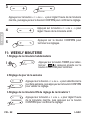
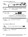
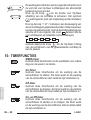
10- FUNZIONI TIMER
Timer SETTIMANALE
Utilizzare questa funzione timer per impostare i tempi di
funzionamento per ogni giorno della settimana.
Timer On
Utilizzare questa funzione timer per attivare il funzionamen-
to del condizionatore. Il timer si attiva ed il condizionatore
comincia a funzionare una volta passato il tempo impostato
.
Timer Off
Utilizzare questa funzione timer per fermare il funzionamen-
to del condizionatore. Il timer si attiva ed il condizionatore
smette di funzionare una volta passato il tempo impostato
.
Timer On e Timer Off
Utilizzare questa funzione timer per attivare
e
fermare il
funzionamento del condizionatore
.
Il timer
si attiva ed il
condizionatore
comincia e
smette di funzionare una volta
passato il tempo impostato
.
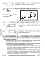
La pagina sta caricando ...
La pagina sta caricando ...
La pagina sta caricando ...
La pagina sta caricando ...
La pagina sta caricando ...
La pagina sta caricando ...
La pagina sta caricando ...
La pagina sta caricando ...
La pagina sta caricando ...
La pagina sta caricando ...
La pagina sta caricando ...
La pagina sta caricando ...
La pagina sta caricando ...
La pagina sta caricando ...
La pagina sta caricando ...
La pagina sta caricando ...
La pagina sta caricando ...
La pagina sta caricando ...
La pagina sta caricando ...
La pagina sta caricando ...
La pagina sta caricando ...
La pagina sta caricando ...
La pagina sta caricando ...
La pagina sta caricando ...
La pagina sta caricando ...
La pagina sta caricando ...
La pagina sta caricando ...
La pagina sta caricando ...
La pagina sta caricando ...
La pagina sta caricando ...
La pagina sta caricando ...
La pagina sta caricando ...
La pagina sta caricando ...
La pagina sta caricando ...
La pagina sta caricando ...
La pagina sta caricando ...
La pagina sta caricando ...
La pagina sta caricando ...
La pagina sta caricando ...
La pagina sta caricando ...
La pagina sta caricando ...
La pagina sta caricando ...
La pagina sta caricando ...
La pagina sta caricando ...
La pagina sta caricando ...
La pagina sta caricando ...
La pagina sta caricando ...
La pagina sta caricando ...
La pagina sta caricando ...
La pagina sta caricando ...
La pagina sta caricando ...
La pagina sta caricando ...
La pagina sta caricando ...
La pagina sta caricando ...
La pagina sta caricando ...
La pagina sta caricando ...
La pagina sta caricando ...
La pagina sta caricando ...
La pagina sta caricando ...
La pagina sta caricando ...
La pagina sta caricando ...
La pagina sta caricando ...
La pagina sta caricando ...
La pagina sta caricando ...
La pagina sta caricando ...
La pagina sta caricando ...
La pagina sta caricando ...
La pagina sta caricando ...
La pagina sta caricando ...
La pagina sta caricando ...
La pagina sta caricando ...
La pagina sta caricando ...
La pagina sta caricando ...
La pagina sta caricando ...
La pagina sta caricando ...
La pagina sta caricando ...
La pagina sta caricando ...
La pagina sta caricando ...
La pagina sta caricando ...
La pagina sta caricando ...
La pagina sta caricando ...
La pagina sta caricando ...
La pagina sta caricando ...
La pagina sta caricando ...
La pagina sta caricando ...
La pagina sta caricando ...
La pagina sta caricando ...
La pagina sta caricando ...
La pagina sta caricando ...
La pagina sta caricando ...
La pagina sta caricando ...
La pagina sta caricando ...
La pagina sta caricando ...
La pagina sta caricando ...
La pagina sta caricando ...
La pagina sta caricando ...
La pagina sta caricando ...
La pagina sta caricando ...
La pagina sta caricando ...
La pagina sta caricando ...
La pagina sta caricando ...
La pagina sta caricando ...
La pagina sta caricando ...
La pagina sta caricando ...
La pagina sta caricando ...
La pagina sta caricando ...
La pagina sta caricando ...
La pagina sta caricando ...
La pagina sta caricando ...
La pagina sta caricando ...
La pagina sta caricando ...
La pagina sta caricando ...
La pagina sta caricando ...
La pagina sta caricando ...
La pagina sta caricando ...
La pagina sta caricando ...
La pagina sta caricando ...
La pagina sta caricando ...
La pagina sta caricando ...
La pagina sta caricando ...
La pagina sta caricando ...
La pagina sta caricando ...
La pagina sta caricando ...
La pagina sta caricando ...
La pagina sta caricando ...
La pagina sta caricando ...
La pagina sta caricando ...
La pagina sta caricando ...
La pagina sta caricando ...
La pagina sta caricando ...
La pagina sta caricando ...
La pagina sta caricando ...
La pagina sta caricando ...
La pagina sta caricando ...
La pagina sta caricando ...
La pagina sta caricando ...
La pagina sta caricando ...
La pagina sta caricando ...
La pagina sta caricando ...
La pagina sta caricando ...
La pagina sta caricando ...
La pagina sta caricando ...
La pagina sta caricando ...
La pagina sta caricando ...
La pagina sta caricando ...
La pagina sta caricando ...
La pagina sta caricando ...
La pagina sta caricando ...
La pagina sta caricando ...
La pagina sta caricando ...
La pagina sta caricando ...
La pagina sta caricando ...
La pagina sta caricando ...
La pagina sta caricando ...
La pagina sta caricando ...
La pagina sta caricando ...
La pagina sta caricando ...
La pagina sta caricando ...
La pagina sta caricando ...
La pagina sta caricando ...
La pagina sta caricando ...
La pagina sta caricando ...
La pagina sta caricando ...
La pagina sta caricando ...
La pagina sta caricando ...
La pagina sta caricando ...
-
 1
1
-
 2
2
-
 3
3
-
 4
4
-
 5
5
-
 6
6
-
 7
7
-
 8
8
-
 9
9
-
 10
10
-
 11
11
-
 12
12
-
 13
13
-
 14
14
-
 15
15
-
 16
16
-
 17
17
-
 18
18
-
 19
19
-
 20
20
-
 21
21
-
 22
22
-
 23
23
-
 24
24
-
 25
25
-
 26
26
-
 27
27
-
 28
28
-
 29
29
-
 30
30
-
 31
31
-
 32
32
-
 33
33
-
 34
34
-
 35
35
-
 36
36
-
 37
37
-
 38
38
-
 39
39
-
 40
40
-
 41
41
-
 42
42
-
 43
43
-
 44
44
-
 45
45
-
 46
46
-
 47
47
-
 48
48
-
 49
49
-
 50
50
-
 51
51
-
 52
52
-
 53
53
-
 54
54
-
 55
55
-
 56
56
-
 57
57
-
 58
58
-
 59
59
-
 60
60
-
 61
61
-
 62
62
-
 63
63
-
 64
64
-
 65
65
-
 66
66
-
 67
67
-
 68
68
-
 69
69
-
 70
70
-
 71
71
-
 72
72
-
 73
73
-
 74
74
-
 75
75
-
 76
76
-
 77
77
-
 78
78
-
 79
79
-
 80
80
-
 81
81
-
 82
82
-
 83
83
-
 84
84
-
 85
85
-
 86
86
-
 87
87
-
 88
88
-
 89
89
-
 90
90
-
 91
91
-
 92
92
-
 93
93
-
 94
94
-
 95
95
-
 96
96
-
 97
97
-
 98
98
-
 99
99
-
 100
100
-
 101
101
-
 102
102
-
 103
103
-
 104
104
-
 105
105
-
 106
106
-
 107
107
-
 108
108
-
 109
109
-
 110
110
-
 111
111
-
 112
112
-
 113
113
-
 114
114
-
 115
115
-
 116
116
-
 117
117
-
 118
118
-
 119
119
-
 120
120
-
 121
121
-
 122
122
-
 123
123
-
 124
124
-
 125
125
-
 126
126
-
 127
127
-
 128
128
-
 129
129
-
 130
130
-
 131
131
-
 132
132
-
 133
133
-
 134
134
-
 135
135
-
 136
136
-
 137
137
-
 138
138
-
 139
139
-
 140
140
-
 141
141
-
 142
142
-
 143
143
-
 144
144
-
 145
145
-
 146
146
-
 147
147
-
 148
148
-
 149
149
-
 150
150
-
 151
151
-
 152
152
-
 153
153
-
 154
154
-
 155
155
-
 156
156
-
 157
157
-
 158
158
-
 159
159
-
 160
160
-
 161
161
-
 162
162
-
 163
163
-
 164
164
-
 165
165
-
 166
166
-
 167
167
-
 168
168
-
 169
169
-
 170
170
-
 171
171
-
 172
172
-
 173
173
-
 174
174
-
 175
175
-
 176
176
-
 177
177
-
 178
178
-
 179
179
-
 180
180
-
 181
181
-
 182
182
-
 183
183
-
 184
184
-
 185
185
-
 186
186


Olimpia Splendid B0969 Manuale utente
- Categoria
- Condizionatori d'aria a sistema split
- Tipo
- Manuale utente
in altre lingue
- English: Olimpia Splendid B0969 User manual
Documenti correlati


Altri documenti
-
 Kaysun WiFi Controller K03 WIFI LCAC Manuale utente
-
Mitsubishi PEH-5EAK Guida d'installazione
-
LG PQRCVSL0QW.ENCXUAE Guida d'installazione
-
Vortice VORT ARTIK EVO UI Istruzioni per l'uso
-
-
 Tekno Point DKV Series Guida d'installazione
-
Argo NEWAGE 18000 BTU/H Installation & User Manual

