
x4
?
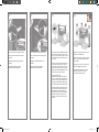
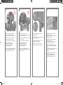
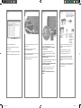
Read these instructions carefully...
What you will need for this procedure
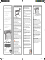
- Because some of the components of the printer
are bulky, you will need up to four people to
lift them. When this is necessary, this symbol is
displayed:
- To assemble the printer you will need at least
3 × 5 m (10 × 16 ft) of empty oor space,
and about four hours.
Lisez attentivement les instructions suivantes...
Conditions requises pour cette procédure
- Dans la mesure où certains des composants de
l’imprimante sont volumineux, jusqu’à quatre
personnes peuvent être requises pour les
soulever. Dans ce cas, le symbole ci-dessous
s’afche :
- Pour assembler l’imprimante, vous devez
disposer d’un espace libre d’au moins 3 × 5 m
et compter environ quatre heures.
Lesen Sie diese Anleitung sorgfältig durch.
Voraussetzungen
- Da einige Komponenten des Druckers sehr
sperrig sind, werden bis zu vier Personen
zum Anheben benötigt. In Situationen, in
denen dies erforderlich, wird dieses Symbol
verwendet:
- Für den Zusammenbau des Druckers wird eine
freie Bodenäche von ca. 3 x 5 m benötigt.
Die Aktion dauert etwa vier Stunden. Für
den Zusammenbau des Druckers wird eine
freie Bodenäche von ca. 3 x 5 m benötigt.
Die Aktion dauert etwa vier Stunden.
Leggete queste istruzioni attentamente...
Cosa è necessario per questa procedura
- Dato il peso di alcuni componenti della
stampante, potrebbero essere necessarie no a
quattro persone per sollevarli. In questo caso,
viene visualizzato il seguente simbolo:
- Per assemblare la stampante è necessario uno
spazio pari a 3 × 5 m e circa quattro ore di
tempo.
HP Designjet 4520 with Scanner.
If you have bought the HP Designjet 4520 with
a scanner, you can reduce the overall setup time
by assembling the scanner rst and then switching
it on. The scanner will take one hour to warm up
when started for the rst time.
HP Designjet 4520 avec scanneur.
Si vous avez acheté l’imprimante HP Designjet 4520
avec un scanneur, vous pouvez réduire le temps
global d’installation en assemblant le scanneur en
premier et en le mettant sous tension. Une heure de
préchauffage est nécessaire au scanneur lors de sa
première utilisation.
HP Designjet 4520 mit Scanner.
Wenn Sie den HP Designjet 4520 mit einem Scanner
erworben haben, können Sie den Zeitaufwand für die
Einrichtung verkürzen, indem Sie zuerst den Scanner
zusammen- bauen und ihn anschließend einschalten.
Der Scanner benötigt nach dem ersten Start eine
Aufwärmphase von 1 Stunde.
HP Designjet 4520 con scanner.
Se avete acquistato HP Designjet 4520 con uno
scanner, potete ridurre il tempo di impostazione
generale assemblando prima lo scanner e quindi
accendendolo. Alla prima accensione, lo scanner
impiegherà un’ora per riscaldarsi.
In case of difculty, please consult:
- Your printer’s Embedded Web Server
- Driver and Documentation CD
En cas de problème, consultez :
- Serveur Web intégré de votre imprimante
- CD contenant le pilote et la documentation
Im Fall von Problemen stehen Ihnen die folgenden
Informationsquellen zur Verfügung:
- Integrierter Web-Server des Druckers
- Treiber- und Dokumentations-CD
In caso di difcoltà, consultare:
- Embedded Web Server della stampante
- CD contenente i driver e la documentazione
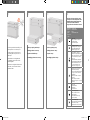
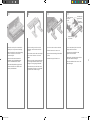
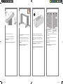
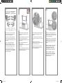
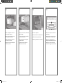
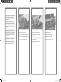
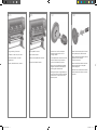
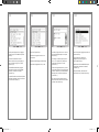
Printer working area
Before you start unpacking, consider where
you are going to put the assembled printer.
You should allow some clear space at the back
and at the front of the printer. The recommended
clearances are shown in the illustration above.
Zone de travail de l’imprimante
Avant de commencer à déballer, pensez
à l’emplacement où l’imprimante assemblée sera
placée. Vous devez ménager un espace à l’avant
et à l’arrière de l’imprimante. Les espaces
recommandés sont indiqués dans l’illustration
ci-dessus.
Aufstellort des Druckers
Überlegen Sie sich vor dem Auspacken, wo
Sie den zusammengebauten Drucker aufstellen
möchten. Vor und hinter dem Drucker muss
freier Raum vorhanden sein. Die empfohlenen
Abstände zu Wänden und anderen Gegen-
ständen sind in der obigen Abbildung
angegeben.
Area operativa della stampante
Prima di cominciare a disimballare la stampante,
considerare lo spazio in cui verrà sistemata una
volta assemblata. È necessario lasciare spazio
sia dietro che davanti alla stampante. Lo spazio
consigliato è illustrato nella gura.
HP Designjet 4520/4520ps
Printer Assembly Instructions
HP Designjet 4520/4520ps
Printer Instructions
d’assemblage
HP Designjet 4520/4520ps
Printer Anleitung zum
Zusammenbau
HP Designjet 4520/4520ps
Printer Istruzioni per
I’installazione
Scanner (mfp only) / Scanneur (mfp uniquement) /
Scanner (nur mfp) / Scanner (solo MFP)
© 2009 Hewlett-Packard Company
Inkjet Commercial Division
Avenida Graells 501 · 08174
Sant Cugat del Vallès
Barcelona · Spain
All rights reserved
Printed in Germany · Imprimé en Allemagne · Stampato in Germania
10 cm
179 cm
CM768-900012.indd 1 03/02/2009 17:57:06

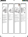
1 2 3 4
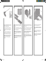
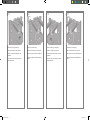
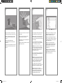
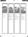
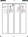
Cut the strap around the boxes carefully, as the
boxes may fall as soon as the strap is cut.
Coupez la sangle qui entoure les cartons
en prenant garde à ce que les cartons ne
tombent pas.
Durchschneiden Sie vorsichtig das Band
um die Behälter. Diese werden nur durch
das Band gehalten.
Fate attenzione nel tagliare la fascetta intorno
alle scatole; una volta rimossa la fascetta
potrebbero cadere.
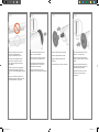
Preliminary unpacking: Outside Europe
Déballage préliminaire : Hors Europe
Auspacken: Außerhalb Europas
Disimballaggio preliminare: Non in Europa
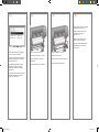
The shapes on the boxes identify the contents.
Les marques sur les cartons indiquent leur contenu.
Die Behälter sind mit Symbolen gekennzeichnet,
an denen sich ihr Inhalt erkennen lässt.
Le gure sulle scatole ne identicano il contenuto.
Mark on box
Marque sur
le carton
Symbol
Segno sulla
scatola
Contents of box
Contenu du carton
Inhalt
Contenuto della scatola
Printer body
Partie principale de l’imprimante
Druckerbasiseinheit
Corpo della stampante
Stand and bin assembly
Assemblage du bac et du support
Sockel-/Ablagefachbaugruppe
Piedistallo e gruppo vassoio
Consumables box, including…
Maintenance Kit (please keep this safe)
Carton des consommables, y compris
le kit de maintenance (à conserver
en lieu sûr)
Verbrauchsmaterialien, einschließlich…
Wartungskit (bitte sicher aufbewahren)
Scatola dei materiali di consumo,
con kit di manutenzione incluso
(da conservare in luogo sicuro)
Spare box (used on page I and J
of these setup instructions)
Carton des pièces détachées (utilisée
à la page I et J de ces instructions
d’installation)
Zubehör (siehe Seite I und J dieser
Anleitung)
Scatola dei pezzi di ricambio
(utilizzata nelle pagine I e J di questo
documento)
Roll module
Module de rouleau
Rolleneinheit
Modulo del rotolo
Scanner body (mfp only)
Partie principale du scanneur
(mfp uniquement)
Scannerbasiseinheit (nur mfp)
Scanner (solo MFP)
Scanner stand (mfp only)
Support du scanneur (mfp uniquement)
Scannersockel (nur mfp)
Piedistallo dello scanner (solo MFP)
Preliminary unpacking: Europe
Déballage préliminaire : Europe
Auspacken: Europa
Disimballaggio preliminare: Europa
CM768-900012.indd 2 03/02/2009 17:57:07

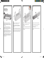
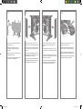
5 6 7 8
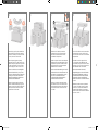
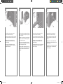
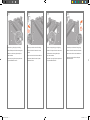
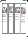
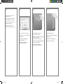
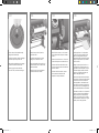
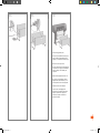
Remove the 2 lids. Place the consumables
and spare boxes in front of the printer body.
Then lower the stand and bin box onto the
consumables and spare boxes.
Retirez les 2 capots. Placez les cartons des pièces
détachées et des consommables devant la partie
principale de l’imprimante. Descendez le carton
du support et du bac sur les cartons des pièces
détachées et des consommables.
Nehmen Sie die beiden Abdeckungen ab. Stellen
Sie die Behälter mit dem Verbrauchsmaterial und
dem Zubehör vor der Basiseinheit der Druckers
ab. Setzen Sie anschließend den Ständer
und den Fachbehälter auf den Behältern für
Verbrauchsmaterial und Zubehör ab.
Rimuovere i 2 coperchi. Posizionate le scatole
dei materiali di consumo e dei ricambi davanti
alla stampante e abbassate il modulo del rotolo
sulle scatole contenenti i materiali di consumo
e i ricambi.
Lower the roll module box onto the consumables
and spare boxes. Then lower the roll module
box onto the oor. Then remove the consumables
and spare boxes.
Descendez le carton du support et du bac
sur les cartons des pièces détachées et des
consommables. Puis placez le carton du module
de rouleau sur le sol. Puis retirez les cartons des
pièces détachées et des consommables.
Heben Sie den Behälter mit der Sockel-/
Ablagefachbaugruppe zunächst auf die Zubehör-
und Verbrauchmaterialbehälter, und stellen Sie
anschließend den Behälter mit der Rolleneinheit
auf den Boden. Stellen Sie anschließend die
Behälter mit dem Zubehör- und Verbrauchmaterial
zur Seite.
Abbassate la scatola contenente il piedistallo
e il vassoio sulle scatole contenenti i materiali
di consumo e i ricambi. Quindi abbassate la
scatola del modulo del rotolo sul pavimento e
rimuovete le altre scatole contenenti i materiali di
consumo e i ricambi.
1
1
2
3
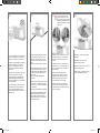
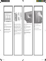
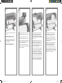
Remove all the upper four plastic handles from
both sides of the box (two each side). Carefully
fold the two side lids up onto the top of the box
as shown, then remove the two boxes.
Retirez les quatre poignées en plastique
supérieures situées sur les deux côtés du carton
(deux de chaque côté). Repliez avec précaution
les deux capots latéraux sur le haut du carton
comme indiqué, puis retirez les deux cartons.
Nehmen Sie die oberen vier Kunststoffgriffe an
den Seiten des Behälters ab (zwei pro Seite).
Klappen Sie die beiden seitlichen Abdeckungen
vorsichtig nach oben auf die Oberseite des
Behälters (siehe Abbildung) und entfernen Sie
anschließend die beiden Behälter.
Rimuovete le quattro maniglie in plastica da
entrambi i lati della scatola (due per ogni lato).
Piegate con cautela i due coperchi laterali sulla
parte superiore della scatola come indicato,
quindi rimuovete le due scatole.
x2 x2
CM768-900012.indd 3 03/02/2009 17:57:08

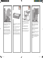
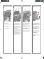
9 10 11 12
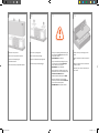
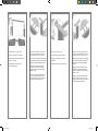
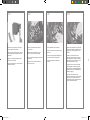
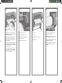
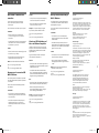
Remove the rst tray containing the parts for
the bin.
Retirez le premier bac contenant les pièces du
bac.
Nehmen Sie den ersten Einsatz mit den Teilen
für das Fach heraus.
Rimuovete il primo vassoio contenente le parti
per il vassoio.
Remove the main printer box.
Retirez le carton principal de l’imprimante.
Nehmen Sie die Verpackung der
Druckerbasiseinheit ab.
Rimuovete la scatola principale della stampante.
Remove the two packing pieces.
Retirez les deux cales d’emballage.
Entfernen Sie die beiden Verpackungsstücke.
Rimuovete le due parti dell’imballaggio.
When you are unpacking the stand assembly, you
will see that there is anti-slip material around two
of the wheels on the feet.
DO NOT REMOVE this material yet.
Lorsque vous déballez l’assemblage du support,
vous constatez qu’une bande antidérapante
entoure deux des roues des pieds.
NE RETIREZ PAS encore cette bande.
Beim Auspacken der Sockelbau-gruppe werden
Sie feststellen, dass sich an zwei Rollen der Füße
rutschhemmendes Material bendet.
Entfernen Sie dieses Material jetzt noch NICHT.
Quando si disimballa il gruppo piedistallo,
noterete la presenza di materiale anti-sdrucciolo
intorno alle due rotelle del piedino.
NON RIMUOVETE ancora questo materiale.
CM768-900012.indd 4 03/02/2009 17:57:08

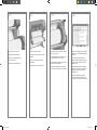
13 14 15 16
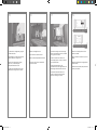
You now need to identify which is the left and
the right side of the cross-brace.
Vous devez à présent identier les côtés
gauche et droit de la traverse.
Stellen Sie fest, welche die linke und welche die
rechte Seite der Querverstrebung ist.
È necessario identicare il lato sinistro e il lato
destro del sostegno.
Remove the second tray from the stand and bin
assembly box. This tray contains the stand legs.
Retirez le second bac du carton de l’assemblage
du bac et du support. Ce bac contient les
montants du support.
Nehmen Sie den zweiten Einsatz aus dem
Behälter der Sockel-/Ablagefachbaugruppe
heraus. Er enthält die Beine des Sockels.
Dalla scatola del piedistallo e gruppo vassoio,
rimuovete il secondo vassoio. Questo vassoio
contieni i piedi stabilizzatori.
From the second tray, remove the two boxes
marked with L and R. Place them on the oor
as shown.
Du second bac, retirez les deux cartons marqués
d’un L et d’un R. Placez-les sur le sol comme
indiqué.
Nehmen Sie aus dem zweiten Einsatz die beiden
mit L und R gekennzeichneten Kästchen heraus,
und legen Sie sie wie gezeigt auf den Boden.
Dal secondo vassoio, rimuovete le due scatole
contrassegnate con le lettere L e R. Posizionatele
sul pavimento come illustrato di seguito.
Lower the cross-brace on to the L and R boxes.
Abaissez la traverse sur les cartons L et R.
Legen Sie die Querverstrebung auf die Kästchen
(L und R).
Abbassate il sostegno sulle scatole L e R.
Two holes/Deux trous
Zwei Löcher/
Due fori
Left/Gauche
Links/Sinistra
Right/Droit
Rechts/Destra
One hole/Un trou
Ein Loch/Un foro
CM768-900012.indd 5 03/02/2009 17:57:08

17 18 19 20
Fix the left leg to the cross-brace using four
screws on the inner side of the leg.
Fixez le montant gauche à la traverse à l’aide
de quatre vis placées sur le côté interne du
montant.
Befestigen Sie das linke Standbein an der
Innenseite mit den vier Schrauben an der
Querverstrebung.
Utilizzando quattro viti sul lato interno del piede
stabilizzatore, ssate il piede stabilizzatore
sinistro al sostegno.
Now you will need the bag of screws and the
screwdriver provided. You may notice that the
screwdriver is slightly magnetic.
Vous devez à présent utiliser le sachet de vis
et le tournevis fournis avec l’imprimante. Vous
remarquerez que le tournevis est légèrement
aimanté.
Sie benötigen jetzt die mitgelieferte Tüte mit
den Schrauben und dem Schraubendreher.
Der Schraubendreher ist leicht magnetisch.
A questo punto, la procedura richiede l’utilizzo
della bustina delle viti e del cacciavite
in dotazione. Il cacciavite è leggermente
magnetico.
Identify the left leg (A) and the right leg (B) as
shown above. Remove the two leg covers from
the left leg.
Identiez le montant gauche (A) et le montant
droit (B) comme illustré ci-dessus. Retirez les deux
plaques du montant gauche.
Identizieren Sie das linke und das rechte
Standbein (A bzw. B in der obigen Abbildung).
Nehmen Sie die beiden Blenden vom linken
Standbein ab.
Identicate il piede stabilizzatore sinistro (A) e il
piede stabilizzatore destro (B) come illustrato di
seguito. Rimuovete le due coperture dal piede
stabilizzatore sinistro.
Lower the left leg onto the left side of the cross-
brace. The left leg will t only on the left side of
the cross-brace.
Abaissez le montant gauche vers le côté gauche
de la traverse. Le montant gauche s’adapte
uniquement au côté gauche de la traverse.
Setzen Sie das linke Standbein auf die linke
Seite der Querverstrebung auf. Es kann nur auf
dieser Seite angebracht werden.
Abbassate il piede stabilizzatore sinistro sul
lato sinistro del sostegno. Il piede stabilizzatore
sinistro può essere ssato soltanto al lato sinistro
del sostegno.
CM768-900012.indd 6 03/02/2009 17:57:09

21 22 23 24
Fix the right leg to the cross-brace using
two screws on the outer side of the leg.
Fixez le montant droit à la traverse à l’aide
de deux vis placées sur le côté externe du
montant.
Befestigen Sie das rechte Standbein an der
Außenseite mit den beiden Schrauben an der
Querverstrebung.
Utilizzando due viti sul lato esterno del piede
stabilizzatore, ssate il piede stabilizzatore
destro al sostegno.
Fix the left leg to the cross-brace using two
screws on the outer side of the leg.
Fixez le montant gauche à la traverse à l’aide de
deux vis placées sur le côté externe du montant.
Befestigen Sie das linke Standbein an der
Außenseite mit den zwei Schrauben an der
Querverstrebung.
Fissate quindi il piede stabilizzatore sinistro
al sostegno utilizzando due viti sul lato esterno
del piede stabilizzatore.
Lower the right leg onto the right side of the cross-
brace. The right leg will t only on the right side
of the cross-brace.
Abaissez le montant droit vers le côté droit de la
traverse. Le montant droit s’adapte uniquement
au côté droit de la traverse.
Setzen Sie das rechte Standbein auf die rechte
Seite der Quer- verstrebung auf. Es kann nur auf
dieser Seite angebracht werden.
Abbassate il piede stabilizzatore destro sul lato
destro del sostegno. Il piede stabilizzatore destro
può essere ssato soltanto al lato destro del
sostegno.
Fix the right leg to the cross-brace using four
screws on the inner side of the leg.
Fixez le montant droit à la traverse à l’aide de
quatre vis placées sur le côté interne du montant.
Befestigen Sie das rechte Standbein an der
Innenseite mit den vier Schrauben an der
Querverstrebung.
Utilizzando quattro viti sul lato interno del piede
stabilizzatore, ssate il piede stabilizzatore
destro al sostegno.
CM768-900012.indd 7 03/02/2009 17:57:09

25 26 27 28
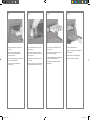
Position a foot on the right leg. There are pins
to help you to position the foot correctly. Do not
remove the anti-slip material from the wheel.
Placez un pied sur le montant droit. Des chevilles
vous permettent de positionner correctement le
pied. Ne retirez pas la bande antidérapante
de la roue.
Positionieren Sie einen Fuß auf dem rechten
Standbein. Dies wird durch die Haltestifte
erleichtert. Entfernen Sie nicht das rutschfeste
Material vom Rad.
Posizionate un piede sul piede stabilizzatore
destro. I piedini consentono di posizionare
il piede correttamente. Non rimuovete ancora il
materiale anti-sdrucciolo dalle rotelle.
Fix the stand cross-bar using four screws.
Fixez la traverse du support avec quatre vis.
Befestigen Sie die Querverstrebung des Sockels
mit den vier Schrauben.
Utilizzando quattro viti, ssate la barra
trasversale del piedistallo.
Position a foot on the left leg. There are pins to
help you to position the foot correctly. Do not
remove the anti-slip material from the wheel.
Placez un pied sur le montant gauche. Des chevilles
vous permettent de positionner correctement le pied.
Ne retirez pas la bande antidérapante de la roue.
Positionieren Sie einen Fuß auf dem linken
Standbein. Dies wird durch die Haltestifte
erleichtert. Entfernen Sie nicht das rutschfeste
Material vom Rad.
Posizionate un piede sul piede stabilizzatore
sinistro. I piedini consentono di posizionare
il piede correttamente. Non rimuovete ancora
il materiale anti-sdrucciolo dalle rotelle.
Fix the left foot using four screws.
Fixez le pied gauche à l’aide de quatre vis.
Befestigen Sie den linken Fuß mit den vier
Schrauben.
Utilizzando quattro viti, ssate il piede sinistro.
CM768-900012.indd 8 03/02/2009 17:57:10

29 30 31 32
Please take note of the colored plugs located
on the legs.
Remarquez les ches de couleur situées sur
les montants.
Beachten Sie die farbigen Stopfen an den
Standbeinen.
Prendete nota dei perni colorati posizionati
sui piedi stabilizzatori.
Fix the right foot using four screws.
Fixez le pied droit à l’aide de quatre vis.
Befestigen Sie den rechten Fuß mit den
vier Schrauben.
Utilizzando quattro viti, ssate il piede destro.
Turn the stand assembly into an upright position
as shown above.
Faites basculer l’assemblage du support
en position verticale comme illustré ci-dessus.
Richten Sie die Sockelbaugruppe wie oben
gezeigt auf.
Ruotate il gruppo piedistallo in posizione
perpendicolare come illustrato.
Open the box containing the roll module.
Remove the plastic bag containing the screws.
Ouvrez le carton contenant le module de
rouleau. Retirez le sac plastique qui contient
les vis.
Öffnen Sie den Behälter mit der Rolleneinheit.
Nehmen Sie die Kunststofftüte mit den
Schrauben ab.
Aprite la scatola contenente il modulo del rotolo.
Rimuovete il sacchetto di plastica contenente
le viti.
x2
Left Leg/Montant gauche
Linkes Standbein/
Piede stabilizzatore
sinistro
Right Leg/Montant droit
Rechtes Standbein/
Piede stabilizzatore
destro
CM768-900012.indd 9 03/02/2009 17:57:10

33 34 35 36
Locate the pin into the right leg.
Enfoncez la cheville dans le montant droit.
Setzen Sie den Stift in das rechte Standbein ein.
Posizionate il piedino nel piede stabilizzatore
destro.
Remove the blue plug on the left leg.
Retirez la che bleue du montant gauche.
Entfernen Sie den blauen Stopfen am linken
Standbein.
Rimuovete il perno blu posizionato sul piede
stabilizzatore sinistro.
Locate the pin into the left leg.
Enfoncez la cheville dans le montant gauche.
Setzen Sie den Stift in das linke Standbein ein.
Posizionate il piedino nel piede stabilizzatore
sinistro.
Remove the blue plug on the right leg.
Retirez la che bleue du montant droit.
Entfernen Sie den blauen Stopfen am rechten
Standbein.
Rimuovete il perno blu posizionato sul piede
stabilizzatore destro.
CM768-900012.indd 10 03/02/2009 17:57:11

37 38 39 40
Locate the pin into the interior of the right leg.
Enfoncez la cheville à l’intérieur du montant droit.
Setzen Sie den Stift in das rechte Standbein ein.
Posizionate il piedino all’interno del piede
stabilizzatore destro.
Remove the top yellow plug on the left leg.
Retirez la che jaune du haut du montant gauche.
Entfernen Sie den oberen gelben Stopfen am
linken Standbein.
Rimuovete il perno giallo superiore posizionato
sul piede stabilizzatore sinistro.
Locate the pin into the interior of the left leg.
Enfoncez la cheville à l’intérieur du montant
gauche.
Setzen Sie den Stift in das linke Standbein ein.
Posizionate il piedino all’interno del piede
stabilizzatore sinistro.
Remove the top yellow plug on the right leg.
Retirez la che jaune du haut du montant droit.
Entfernen Sie den oberen gelben Stopfen
am rechten Standbein.
Rimuovete il perno giallo superiore posizionato
sul piede stabilizzatore destro.
CM768-900012.indd 11 03/02/2009 17:57:12

41 42 43 44
Slide Drawer 1 out until it touches the foam
packaging.
Faites glisser le Tiroir 1 jusqu’à ce qu’il
touche l’emballage en mousse.
Ziehen Sie den Einschub 1 heraus, bis er die
Styroporverpackung berührt.
Estraete il cassetto 1 facendolo scorrere no
a toccare gli imballaggi di polistirolo.
You now need to identify the left and right of the
printer. This information is shown on the foam
end packs. Also identify the rear of the printer.
Vous devez à présent identier les côtés gauche
et droit de l’imprimante. Ces informations
gurent sur les emballages en mousse, aux
extrémités. Identiez également l’arrière de
l’imprimante.
Stellen Sie nun fest, welche die linke und welche
die rechte Seite des Druckers ist. Auf den
Styroporabdeckungen an den beiden Seiten
benden sich entsprechende Beschriftungen.
Stellen Sie außerdem fest, wo sich die Rückseite
des Druckers bendet.
È necessario identicare il lato sinistro e il lato
destro della stampante. Queste informazioni
sono riportate sull’imballaggio laterale di
polistirolo. Identicate anche il lato posteriore
della stampante.
Pull open the protective plastic from the base of
the printer. Please ensure that there is a three-
meter space clear of obstructions to the rear
of the printer and one meter at the front of the
printer.
Remove the two desiccant bags from the printer.
Retirez le plastique de protection en commençant
par la base de l’imprimante. Assurez-vous que
vous disposez d’un espace dégagé d’au moins
trois mètres à l’arrière de l’imprimante et d’un
mètre à l’avant.
Retirez les deux sachets déshydratants de
l’imprimante.
Öffnen Sie die Schutzhülle des Druckers. Achten
Sie darauf, dass an der Rückseite des Druckers
ein Freiraum von 3 m und an der Vorderseite von
1 m vorhanden ist.
Entfernen Sie die beiden Beutel mit Trockenmittel.
Togliete la plastica protettiva dalla base della
stampante. Vericate che siano disponibili
almeno tre metri di spazio libero dal lato
posteriore della stampante e un metro dal lato
anteriore della stampante.
Using the screwdriver supplied, remove the two
screws that hold Drawer 1 in place. Note: the
screws are only for transit, they are not to be
replaced.
A l’aide du tournevis fourni, retirez les deux vis
qui tiennent le Tiroir 1 en place. Remarque : Les
vis ne servent qu’au transport, elles ne doivent
pas être replacées.
Entfernen Sie die beiden Schrauben, mit
denen der Einschub 1 befestigt ist, mit dem
mitgelieferten Schraubenzieher. Hinweis: Die
Schrauben dienen nur zu Transportzwecken
und werden später nicht mehr benötigt.
Utilizzando il cacciavite fornito in dotazione,
rimuovete le due viti che sostengono il cassetto 1
in posizione. Nota: le viti sono temporanee, non
devono essere sostituite.
Do not replace these screws after
removal!/Ne réinsérez pas ces vis
après leur retrait !/Bringen Sie diese
Schrauben nach dem Entfernen nicht
erneut an./Non reinserite le viti dopo
averle rimosse.
CM768-900012.indd 12 03/02/2009 17:57:12

45 46 47 48
Slide Drawer 1 forwards to gain better access
for the front screw. Fix the left side of the stand
to the printer using two screws. Make sure that
the screws are fully tightened.
Faites glisser le Tiroir 1 vers l’avant an d’avoir
un meilleur accès à la vis avant. Fixez le côté
gauche du support à l’imprimante à l’aide de
deux vis. Assurez-vous que les vis sont bien
serrées.
Ziehen Sie den Einschub 1 nach vorne, damit
die vordere Schraube besser zugänglich
ist. Befestigen Sie die linke Seite der
Sockelbaugruppe mit zwei Schrauben am
Drucker. Ziehen Sie die Schrauben fest an.
Fate scorrere il cassetto 1 in avanti per
accedere alla vite anteriore. Utilizzando
due viti, ssate il lato sinistro del piedistallo
alla stampante. Assicuratevi che siano
completamente serrate.
Advance warning: in the next step, make sure
you position the stand pins in the holes in the
center of the printer body brackets.
Avertissement : Au cours de l’étape suivante,
assurez-vous de placer les chevilles dans les trous
au centre des attaches de la partie principale de
l’imprimante.
Achtung: Im nächsten Schritt müssen die
Stifte am Sockel unbedingt in die dafür
vorgesehenen Aussparungen in den Schienen
der Druckerbasiseinheit eingepasst werden.
Avvertenza: nell’operazione successiva,
assicuratevi di collocare i piedini del piedistallo
in corrispondenza dei fori al centro delle staffe
del corpo della stampante.
Lift the stand assembly onto the printer body.
The anti-slip material should face to the rear
of the printer.
Soulevez l’assemblage du support pour le poser
sur la partie principale de l’imprimante.
La bande antidérapante doit être face à l’arrière
de l’imprimante.
Heben Sie die Sockelbaugruppe auf die
Druckerbasiseinheit.
Das rutschfeste Material muss zur Rückseite des
Druckers zeigen.
Sollevate il gruppo piedistallo sulla stampante.Il
materiale anti-sdrucciolo deve essere rivolto verso
il lato posteriore della stampante.
Fix the right side of the stand to the printer using
one screw. Make sure that the screw is fully
tightened.
Fixez le côté droit du support à l’imprimante à
l’aide d’une vis. Assurez-vous que la vis est bien
serrée.
Befestigen Sie die rechte Seite der
Sockelbaugruppe mit einer Schraube am Drucker.
Ziehen Sie die Schraube fest an.
Utilizzando una vite, ssate il lato destro del
piedistallo alla stampante. Assicuratevi che la
vite sia completamente serrata.
Left Leg/Montant gauche
Linkes Standbein/Piede
stabilizzatore sinistro
Right Leg/Montant droit
Rechtes Standbein/
Piede stabilizzatore destro
x2
CM768-900012.indd 13 03/02/2009 17:57:13

49 50 51 52
Remove the roll module from the plastic bag.
Retirez le module de rouleau du sac plastique.
Nehmen Sie die Rolleneinheit aus der
Kunststoffverpackung.
Rimuovete il modulo del rotolo dal sacchetto di
plastica.
Before unpacking the roll module, note that
you should only handle this piece of equipment
using the points indicated by the green arrows
shown above.
Avant de déballer le module de rouleau,
remarquez que vous ne devez manipuler cette
pièce qu’en utilisant les points indiqués par les
èches vertes illustrées ci-dessus.
Die Rolleneinheit darf beim Auspacken nur an
den Stellen angefasst werden, die in der obigen
Abbildung mit grünen Pfeilen markiert sind.
Prima di disimballare il modulo del rotolo, tenete
presente che è necessario maneggiare questo
pezzo di apparecchiatura solo nei punti indicati
dalle frecce verdi.
Open the box containing the roll module,
then remove the two foam supports.
Ouvrez le carton contenant le module de
rouleau, puis retirez les deux protections en
mousse.
Öffnen Sie den Behälter mit der Rolleneinheit,
und entfernen Sie die beiden Styroporelemente.
Aprite la scatola contenente il modulo del rotolo,
quindi rimuovete i due supporti di polistirolo.
Remove the roll module from the packaging box.
Retirez le module de rouleau du carton
d’emballage.
Nehmen Sie die Rolleneinheit aus dem Behälter.
Rimuovete il modulo del rotolo dalla scatola di
imballaggio.
Important information
Informations importantes
Wichtige Informationen
Informazioni importanti
x4
CM768-900012.indd 14 03/02/2009 17:57:13

53 54 55 56
Before the roll module is moved into its nal
position, please note that the roll module
should sit on the pins that were located on
the stand legs earlier.
Avant de déplacer le module de rouleau vers
sa position nale, vous devez le placer sur
les chevilles repérées précédemment sur les
montants du support.
An der Rolleneinheit benden sich Aussparungen
für die Stifte, die Sie an den Standbeinen
angebracht haben.
Prima di spostare il modulo del rotolo nella
posizione nale, tenete presente che esso deve
essere collocato sui piedini precedentemente
posizionati sui piedi stabilizzatori del
piedistallo.
Remove the remaining two yellow plugs from the
left and right legs. It is important to remember
the positions of these holes.
Retirez les deux ches jaunes restantes des
montants gauche et droit. Il est important de
mémoriser la position de ces trous.
Nehmen Sie die beiden verbliebenen gelben
Stopfen am linken und rechten Standbein ab.
Merken Sie sich die Positionen dieser Öffnungen.
Rimuovete i due perni gialli rimanenti dai piedi
stabilizzatori destro e sinistro. È importante che
ricordiate le posizioni di questi fori.
Turn the roll module over into an inverted position
as shown above. Then carry it to the front of the
inverted printer.
Retournez le module de rouleau comme illustré
ci-dessus. Puis, placez-le face à l’avant de
l’imprimante retournée.
Drehen Sie die Rolleneinheit in die oben gezeigte
Position. Schieben Sie sie anschließend an die
Vorderseite des umgedrehten Druckers.
Ruotate il modulo del rotolo in una posizione
capovolta come illustrato. Quindi trascinatelo
sulla parte anteriore della stampante capovolta.
Rest the roll module next to the rst printer
crossbar.
Posez le module de rouleau à côté de
la première traverse de l’imprimante.
Setzen Sie die Rolleneinheit an der ersten
Querverstrebung des Druckers an.
Posizionate il modulo del rotolo accanto alla
prima barra trasversale della stampante.
x4x4
Rear of the printer/
Arrière de l’imprimante/Rückansicht des
Druckers/Lato posteriore della stampante
CM768-900012.indd 15 03/02/2009 17:57:14

57 58 59 60
Fix the roll module to the left leg of the stand
using two collar-headed screws.
Fixez le module de rouleau au montant gauche
du support à l’aide de deux vis à embase
supplémentaires.
Befestigen Sie die Rolleneinheit mit zwei
Bundschrauben am linken Standbein der
Sockelbaugruppe.
Fissate il modulo del rotolo sul piede
stabilizzatore sinistro del piedistallo utilizzando
le due viti a testa piatta.
Three people are needed, two at the front and
one at the rear of the printer. The two at the front
should lift the roll module and then, with the help
of the third person at the rear, lower it vertically
onto the pins located earlier on the stand.
Trois personnes sont nécessaires, deux à l’avant
et une à l’arrière de l’imprimante. Les deux
personnes à l’avant doivent soulever le module
de rouleau, puis, avec l’aide de la troisième
personne à l’arrière, l’abaisser verticalement sur
chevilles repérées précédemment sur le support.
Es werden drei Personen benötigt: zwei an der
Vorderseite und eine Person an der Rückseite
des Druckers. Die beiden Personen an der
Vorderseite heben die Rolleneinheit an und
senken sie dann mit Hilfe der dritten Person
an der Rückseite des Druckers senkrecht auf
die Haltestifte am Standfuß ab.
Sono necessarie tre persone, due posizionate
nella parte anteriore e una nella parte posteriore
della stampante. Le due persone posizionate
nella parte anteriore della stampante devono
sollevare il modulo del rotolo e, con l’aiuto della
terza persona posizionata sul retro, abbassarlo,
in senso verticale, sui piedini posizionati
precedentemente sul piedistallo.
Look at the front of the roll module and check
that it comes close to the legs of the stand.
Examinez l’avant du module de rouleau et
vériez s’il est proche des montants du support.
Sehen Sie auf der Vorderseite der Rolleneinheit
nach, ob sie sich in der Nähe der Standfüße
bendet.
Osservando frontalmente, assicuratevi che il
modulo del rotolo venga collocato sui piedi
stabilizzatori del piedistallo.
Fix the roll module to the right leg of the stand
using two additional screws.
Fixez le module de rouleau au montant droit du
support à l’aide de deux vis supplémentaires.
Befestigen Sie die Rolleneinheit mit zwei
zusätzlichen Schrauben am rechten Standbein.
Fissate il modulo del rotolo sul piede
stabilizzatore destro del piedistallo utilizzando le
due viti addizionali.
x3
x2
x1
CM768-900012.indd 16 03/02/2009 17:57:14

61 62 63 64
Using four people, rotate the printer on to the
spare and consumables boxes.
Aidé de trois personnes, basculez l’imprimante
vers les cartons des pièces détachées et des
consommables.
Kippen Sie den Drucker mit vier Personen auf
die zuvor hingelegten Verpackungen.
Capovolgete la stampante sopra le scatole
dei materiali di consumo e dei ricambi
(sono necessarie quattro persone).
Fix the roll module to the right leg of the stand.
Fixez le module de rouleau au montant droit
du support.
Befestigen Sie die Rolleneinheit afm rechten
Standfuß.
Fissate il modulo del rotolo sul piede
stabilizzatore destro del piedistallo.
Fix the roll module to the left leg of the stand.
Fixez le module de rouleau au montant gauche
du support.
Befestigen Sie die Rolleneinheit am linken
Standbein.
Fissate il modulo del rotolo sul piede
stabilizzatore sinistro del piedistallo.
Place the spare and consumables boxes against
the rear of the printer box. The arrows on the
boxes must point towards the printer box. Check
that the anti-slip material is still xed to the two
rear wheels.
Placez les cartons des pièces détachées et des
consommables contre l’arrière du carton de
l’imprimante. Les èches situées sur les cartons
doivent pointer vers le carton de l’imprimante.
Vériez que la bande antidérapante est toujours
xée aux deux roues situées à l’arrière.
Legen Sie die Ersatz- und
Verbrauchsmaterialverpackungen hinten am
Drucker an. Die Pfeile auf den Verpackungen
müssen zum Drucker zeigen. Vergewissern Sie
sich, dass sich das rutschfeste Material immer
noch auf den beiden hinteren Rädern bendet.
Accostate le scatole dei materiali di consumo
e dei ricambi al lato posteriore della scatola
della stampante. Le frecce disegnate sulle
scatole devono puntare verso la scatola della
stampante. Vericate che il materiale anti-
sdrucciolo sia ancora ssato alle due rotelle
posteriori.
x4
CM768-900012.indd 17 03/02/2009 17:57:15

65 66 67 68
Rotate the printer into an upright position.
The anti-slip material should stop the printer
from sliding forwards.
Faites pivoter l’imprimante pour la mettre en
position verticale. La bande antidérapante doit
empêcher l’imprimante de glisser vers l’avant.
Bringen Sie den Drucker in eine aufrechte
Position. Das rutschfeste Material verhindert,
dass der Drucker nach vorne rutscht.
Ruotate la stampante in posizione perpendicolare.
Il materiale anti-sdrucciolo evita che la stampante
scivoli in avanti.
Rotate the printer until its rear rests on the spare
and consumables boxes and the wheels with the
anti-slip material touch the oor.
Basculez l’imprimante jusqu’à ce que l’arrière
repose sur les cartons des pièces détachées
et des consommables et que les roues avec
la bande antidérapante touchent le sol.
Kippen Sie den Drucker, bis seine Rückseite auf
den Ersatz- und Verbrauchsmaterialverpackungen
auiegt und die Räder mit dem rutschfesten
Material den Boden berühren.
Ruotate la stampante nché il lato posteriore
non si appoggia alle scatole e le rotelle su
cui è presente il materiale anti-sdrucciolo non
toccano il pavimento.
Remove the pallet before trying to lift the printer
into an upright position.
Retirez la palette avant de mettre l’imprimante en
position verticale.
Entfernen Sie die Palette, bevor Sie den Drucker
aufstellen.
Rimuovere il ripiano su cui appoggia la
stampante prima di sollevarla per metterla
in posizione perpendicolare.
Using four people and the hand holds on the
rear of the printer body, carefully lift the printer
into an upright position.
Aidé de trois personnes et avec une prise
de main sur l’arrière de la partie principale
de l’imprimante, soulevez l’imprimante avec
précaution pour la mettre en position verticale.
Fassen Sie mit vier Personen hinten am Drucker
an, und richten Sie ihn vorsichtig auf.
Sollevate con cautela la stampante ponendola
in posizione perpendicolare. Sono necessarie
quattro persone e l’utilizzo delle maniglie sul retro
della stampante.
x4
CM768-900012.indd 18 03/02/2009 17:57:15

69 70 71 72
Remove the anti-slip material from the two rear
wheels on the stand assembly.
Retirez la bande antidérapante des deux roues
situées à l’arrière sur l’assemblage du support.
Entfernen Sie das rutschfeste Material von den
beiden hinteren Rädern der Sockelbaugruppe.
Rimuovete il materiale anti-sdrucciolo dalle due
rotelle posteriori del gruppo piedistallo.
Remove the two foam end packs and the plastic
covering the printer.
Retirez les deux emballages en mousse
aux extrémités et le plastique qui protègent
l’imprimante.
Entfernen Sie die beiden Styroporendstücke und
die Plastikhülle des Druckers.
Rimuovete i due imballaggi laterali di polistirolo
e la plastica che copre la stampante.
Position the left leg cover on the front of the
left leg (1), then clip the rear edge (2) into place.
Placez la plaque du montant gauche à l’avant
du montant gauche (1), puis enclenchez le bord
arrière (2).
Setzen Sie die linke Standbeinblende vorne am
linken Standbein an (1), und drücken Sie hinten
auf die Blende (2), bis sie einrastet.
Posizionate il coperchio del piede stabilizzatore
sinistro davanti al piede stabilizzatore sinistro (1),
quindi agganciate il bordo posteriore (2).
Position the right leg cover on the front of the
right leg (1), then clip the rear edge (2) into
place.
Placez la plaque du montant droit à l’avant du
montant droit (1), puis enclenchez le bord arrière
(2).
Setzen Sie die Standbeinblende vorne am rechte
Standbein an (1), und drücken Sie hinten auf die
Blende (2), bis sie einrastet.
Posizionate il coperchio del piede stabilizzatore
destro davanti al piede stabilizzatore destro (1),
quindi agganciate il bordo posteriore (2).
CM768-900012.indd 19 03/02/2009 17:57:16

73 74 75 76
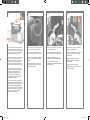
Open the printhead cleaner door and remove
the carriage packing material. Then close the
cleaner door.
Ouvrez la porte du dispositif de nettoyage
de la tête d’impression et retirez le matériel
d’emballage du chariot. Fermez ensuite le
volet du dispositif de nettoyage.
Öffnen Sie die Druckkopfreinigerklappe,
und entfernen Sie das Verpackungsmaterial.
Schließen Sie danach die
Druckkopfreinigerklappe wieder.
Aprite lo sportello dei puliscitestine e rimuovete
il materiale dai carrelli. Chiudete lo sportello
dei puliscitestine.
Remove the packing tapes 1 to 10.
Retirez les rubans adhésifs d’emballage 1 à 10.
Entfernen Sie das Klebeband 1 bis 10.
Rimuovete i nastri di imballaggio da 1 a 10.
Open the printer window. Then remove the
two window inserts and the ink tube packing
material.
Ouvrez le capot de l’imprimante. Puis retirez
les deux inserts de fenêtre ainsi que le matériel
d’emballage du tube d’encre.
Öffnen Sie das Druckerfenster. Entfernen Sie
anschließend die beiden Fenstereinsätze und das
Verpackungsmaterial der Tintenschläuche.
Aprite la nestra della stampante. Quindi
rimuovete i due inserti della nestra e il materiale
di imballaggio del tubo di inchiostro.
Remove the protective covering from the printer
window and the front panel screen.
Retirez l’enveloppe de protection du capot de
l’imprimante et de l’écran du panneau avant.
Ziehen Sie die Schutzfolie vom Druckerfenster
und von der Bedienfeldanzeige ab.
Rimuovete la copertura protettiva dalla nestra
della stampante e dal pannello frontale.
CM768-900012.indd 20 03/02/2009 17:57:16
La pagina si sta caricando...
La pagina si sta caricando...
La pagina si sta caricando...
La pagina si sta caricando...
La pagina si sta caricando...
La pagina si sta caricando...
La pagina si sta caricando...
La pagina si sta caricando...
La pagina si sta caricando...
La pagina si sta caricando...
La pagina si sta caricando...
La pagina si sta caricando...
La pagina si sta caricando...
La pagina si sta caricando...
La pagina si sta caricando...
La pagina si sta caricando...
La pagina si sta caricando...
La pagina si sta caricando...
La pagina si sta caricando...
La pagina si sta caricando...
La pagina si sta caricando...
La pagina si sta caricando...
La pagina si sta caricando...
La pagina si sta caricando...
-
 1
1
-
 2
2
-
 3
3
-
 4
4
-
 5
5
-
 6
6
-
 7
7
-
 8
8
-
 9
9
-
 10
10
-
 11
11
-
 12
12
-
 13
13
-
 14
14
-
 15
15
-
 16
16
-
 17
17
-
 18
18
-
 19
19
-
 20
20
-
 21
21
-
 22
22
-
 23
23
-
 24
24
-
 25
25
-
 26
26
-
 27
27
-
 28
28
-
 29
29
-
 30
30
-
 31
31
-
 32
32
-
 33
33
-
 34
34
-
 35
35
-
 36
36
-
 37
37
-
 38
38
-
 39
39
-
 40
40
-
 41
41
-
 42
42
-
 43
43
-
 44
44


HP DesignJet 4520 Printer series Assembly Instructions
- Tipo
- Assembly Instructions
- Questo manuale è adatto anche per
in altre lingue
- English: HP DesignJet 4520 Printer series
- français: HP DesignJet 4520 Printer series
- Deutsch: HP DesignJet 4520 Printer series
Documenti correlati
-
HP DesignJet 4020 Printer series Assembly Instructions
-
-
-
-
-
-
-
-
HP DesignJet T830 Istruzioni per l'uso
-