Mitsubishi PEH-10MYA Guida d'installazione
- Categoria
- Condizionatori d'aria a sistema split
- Tipo
- Guida d'installazione
Questo manuale è adatto anche per

Air-Conditioners
INDOOR UNIT
PEH-RP8, 10MYA
FOR INSTALLER
FÜR INSTALLATEURE
POUR L’INSTALLATEUR
PARA EL INSTALADOR
PER L’INSTALLATORE
VOOR DE INSTALLATEUR
FÖR INSTALLATÖREN
TIL MONTØREN
PARA O INSTALADOR
°π∞ ∆√¡ ∆∂áπ∫√ ∂°∫∞∆∞™∆∞™∏™
TES‹SATÇININ D‹KKAT‹NE
ДЛЯ СПЕЦИАЛИСТА ПО МОНТАЖУ
INSTALLATION MANUAL
For safe and correct use, please read this installation manual thoroughly before installing the air-conditioner unit.
INSTALLATIONSHANDBUCH
Zum sicheren und ordnungsgemäßen Gebrauch der Klimageräte das Installationshandbuch gründlich durchlesen.
MANUEL D’INSTALLATION
Veuillez lire le manuel d’installation en entier avant d’installer ce climatiseur pour éviter tout accident et vous assurer d’une utilisation correcte.
MANUAL DE INSTALACIÓN
Para un uso seguro y correcto, lea detalladamente este manual de instalación antes de montar la unidad de aire acondicionado.
MANUALE DI INSTALLAZIONE
Per un uso sicuro e corretto, leggere attentamente questo manuale di installazione prima di installare il condizionatore d’aria.
INSTALLATIEHANDLEIDING
Voor een veilig en juist gebruik moet u deze installatiehandleiding grondig doorlezen voordat u de airconditioner installeert.
INSTALLATIONSMANUAL
Läs denna installationsmanual noga för säkert och korrekt bruk innan luftkonditioneringen installeras.
INSTALLATIONSMANUAL
Læs venligst denne installationsmanual grundigt, før De installerer airconditionanlægget, af hensyn til sikker og korrekt anvendelse.
MANUAL DE INSTALAÇÃO
Para segurança e utilização correctas, leia atentamente este manual de instalação antes de instalar a unidade de ar condicionado.
E°XEIPI¢IO O¢H°IøN E°KATA™TA™H™
°È· ·ÛÊ¿ÏÂÈ· Î·È ÛˆÛÙ‹ ¯Ú‹ÛË, ·Ú·Î·Ï›ÛÙ ‰È·‚¿ÛÂÙ ÚÔÛ¯ÙÈο ·˘Ùfi ÙÔ ÂÁ¯ÂÈÚ›‰ÈÔ ÂÁηٿÛÙ·Û˘ ÚÈÓ ·Ú¯›ÛÂÙ ÙËÓ
ÂÁηٿÛÙ·ÛË Ù˘ ÌÔÓ¿‰·˜ ÎÏÈÌ·ÙÈÛÌÔ‡.
MONTAJ ELK‹TABI
Emniyetli ve do¤ru biçimde nas›l kullan›laca¤›n› ö¤renmek için lütfen klima cihaz›n› monte etmeden önce bu elkitab›n› dikkatle okuyunuz.
РУКОВОДСТВО ПО УСТАНОВКЕ
Для осторожного и правильного использования прибора необходимо тщательно ознакомиться с данным руководством по
установке до выполнения установки кондиционера.
DK
SW
NL
I
E
F
D
GB
RU
TR
GR
P

2
[Fig. 2.0.1]
A
B
B
C
C
A Air outlet
B Remote controller
C Joint pipe for R410A (Field piping connection)
* In case of PEH-RP8 only
2
3
200530
131 200 19932
20
PEH-RP10: 1440
PEH-RP8: 1240
20
200400
730
7525928
428500
1
2
3
A
A
C
D
B
B
PEH-RP10: 1480
PEH-RP8: 1280
PEH-RP10: 2080 PEH-RP8: 1880
1 When connecting air inlet
2 When installing the suspension fixtures prior to installation of the
indoor unit without inlet duct
3 When hanging the indoor unit directly without inlet duct
A Service space B Suspension bolt pitch
C Air inlet D Air outlet
[Fig. 3.2.1]
F
G
H
A
B
D
C
E
E
4
4.1
A Ceiling board
B Edge beam
C Tie beam
D Square timber for hanging the air conditioner
E Pitch
F Insert: 100 to 150 kg (1 piece) (field supply)
G M10 hanging bolt (field supply)
H Reinforcement
[Fig. 4.1.1] [Fig. 4.1.2]
3.2
[Fig. 3.2.2]
20
199200
562
13122
C
D
B
B
F
GH
E
I
PEH-RP10: 1580
PEH-RP8: 1380
PEH-RP10: 1480
PEH-RP8: 1280
E Top of the unit
F 4-ø12 suspension bolt holes
G Control box
H Drain pan
I Main body
5
5.1
A30
B
A
B
A
*1
A30
B
10
A
A
B
[Fig. 5.1.1] [Fig. 5.1.2] [Fig. 5.1.3]
A Unit body
B Lifting machine
A Nut
B Washer
A Be sure to attach a U-shaped washer (4 wash-
ers in total).

3
GB
D
F
SWI
NL
E
P
6.2
5.2
A
6
95
40
100
152 156
42
C
A
B
A Refrigerant pipe
(liquid pipe)
B Refrigerant pipe
(gas pipe)
C Drain pipe
[Fig. 5.2.1]
[Fig. 6.2.1]
A
A
E
C
F
B
D
7
7.1
A
H
A
C
A
E
G
B
E
D
F
[Fig. 7.1.1] [Fig. 7.1.2]
A Thermal insulation
B Pull out insulation
C Wrap with damp cloth
D Return to original position
E Ensure that there is no gap here
F Wrap with insulating tape
A Brazing
B Flare joint
C Gas pipe
D Liquid pipe
E Service port
F Indoor unit
G Outdoor unit
H Joint pipe (Accessory part ) * Only for PEH-RP8 when connecting to R410A outdoor unit
[Fig.7.1.3]
7.2
[Fig.7.2.1]
A
A Remove the cap
A
B
G
F
D
H
I
J
E
C
A Insulator
B Drain pipe Rc1
C Drain pan
D
>
=
70 mm
E
>
=
2 × F
>
=
70 mm
F
>
=
35 mm
G Downward slope 20 mm/m or more
H Drain trap
I The drain pipe should extend below this level.
J Open drain
8
F
A
B
D C
E
GG
E
B
C
D
A
12.5
25~100 mm
10 mm
[Fig.8.0.1]
A Air inlet B Air outlet
C Access door D Ceiling surface
E Canvas duct F Keep duct-work length 850 or more
G Connect common reference potential wire between duct-work to air conditioner
[Fig.8.0.2]
A Inlet duct flange B Inlet temperature sensor
C Sensor protection plate D Sensor fixture
E Inlet duct
A Level check

4
GB
D
F
SWI
NL
E
P
[Fig.8.0.3]
B
C
A
H
I
E
G
D
F
E
A
34
45
98
25
60
20
1000
PEH-RP8 : 1102
PEH-RP10 : 1302
PEH-RP8 : 31
PEH-RP10 : 66
PEH-RP8 : 120
PEH-RP10 : 220
250
380
A Inlet duct flange
B PEH-RP8: 8 × 130pitch = 1040
PEH-RP10: 9 × 130pitch = 1170
C PEH-RP8: 24-ø3 holes (Inlet duct mount holes)
PEH-RP10: 26-ø3 holes (Inlet duct mount holes)
D Top of the unit
E Outlet duct flange
F PEH-RP8,10: 7 × 130pitch = 910
G PEH-RP8,10: 22-ø3 holes (Outlet duct mount holes)
H PEH-RP8,10: 2 × 130pitch = 260
I PEH-RP8,10: 2 × 100pitch = 200
8
[Fig.9.3.1]
(1) (2)
[Fig.9.4.1]
30
46
30
30120
83.5
C
A
B
D
(1)
9
9.1
[Fig.9.1.1]
(2)
(3)
A Remote controller pro-
file
B Required clearances
surrounding the re-
mote controller
C Temperature sensor
D Installation pitch
C Wall D Conduit
E Lock nut F Bushing
G Switch box H Remote controller cord
I Seal with putty.
F
H
C
D
E
G
I
I
B-1.
B-2.
I
[Fig.9.2.1]
9.2
<A> For installation in the switch box: <B> For direct installation on the wall
select one of the following:
<A> For installation in the switch box <B> For direct installation on the wall
[Fig.9.2.2]
9.3
PAR-20MAA
ON/OFF
CENTRALLY CONTROLLED
ERROR CODE
CLOCK
ON OFF
˚C
CHECK
CHECK MODE
FILTER
TEST RUN
FUNCTION
˚C
1Hr.
NOT AVAILABLE
STAND BY
DEFROST
FILTER
CHECK TEST
TEMP.
TIMER SET
F
G
E
H
B
A
4321
DC
C Switch box for two pieces D Remote controller cord
E Cross-recessed, pan-head screw
G Seal the remote controller cord service entrance with putty
H Wood screw
H
D
E
D
C
G
AB
TB6
A
B
1
234
ON
1
234
ON
A To TB5 on the indoor unit
B Terminal block representation
No polarity
⁄
1
Mode number ⁄
2
Setting number
⁄
3
Refrigerant address ⁄
4
Unit number
9.4

5
GB
D
F
SWI
NL
E
P
ON/OFF TEMP
FAN
VANE
TEST RUN
AUTO STOP
AUTO START
h
min
LOUVER
MODE
CHECK
RESETSET CLOCK
CHECK
E
C,D
F
A
B
9
9.4
[Fig.9.4.2]
3
STAND BY
DEFROST
INDOOR UNIT
ADDRESS NO
CLOCK
ON OFF
˚C
1Hr.
˚C
CHECK MODE
FILTER
CLOCK
FUNCTION
STAND BY
DEFROST
INDOOR UNIT
ADDRESS NO
CLOCK
ON OFF
˚C
1Hr.
˚C
CHECK MODE
FILTER
CLOCK
FUNCTION
STAND BY
DEFROST
INDOOR UNIT
ADDRESS NO
CLOCK
ON OFF
˚C
1Hr.
˚C
CHECK MODE
FILTER
CLOCK
FUNCTION
STAND BY
DEFROST
INDOOR UNIT
ADDRESS NO
CLOCK
ON OFF
˚C
1Hr.
˚C
CHECK MODE
FILTER
CLOCK
FUNCTION
4
1
2
4
1
STAND BY
DEFROST
INDOOR UNIT
ADDRESS NO
CLOCK
ON OFF
˚C
1Hr.
˚C
CHECK MODE
FILTER
CLOCK
FUNCTION
3
1
STAND BY
DEFROST
INDOOR UNIT
ADDRESS NO
CLOCK
ON OFF
˚C
1Hr.
˚C
CHECK MODE
FILTER
CLOCK
FUNCTION
5
2
2
STAND BY
DEFROST
INDOOR UNIT
ADDRESS NO
CLOCK
ON OFF
˚C
1Hr.
˚C
CHECK MODE
FILTER
CLOCK
FUNCTION
STAND BY
DEFROST
INDOOR UNIT
ADDRESS NO
CLOCK
ON OFF
˚C
1Hr.
˚C
CHECK MODE
FILTER
CLOCK
FUNCTION
STAND BY
DEFROST
INDOOR UNIT
ADDRESS NO
CLOCK
ON OFF
˚C
1Hr.
˚C
CHECK MODE
FILTER
CLOCK
FUNCTION
STAND BY
DEFROST
INDOOR UNIT
ADDRESS NO
CLOCK
ON OFF
˚C
1Hr.
˚C
CHECK MODE
FILTER
CLOCK
FUNCTION
21
STAND BY
DEFROST
INDOOR UNIT
ADDRESS NO
CLOCK
ON OFF
˚C
1Hr.
˚C
CHECK MODE
FILTER
CLOCK
6
7
8
[Fig.9.4.4]
1
2
3
4
CHECK
CHECK
CHECK
CHECK
(a)
(b)
(d)(c)
(a) Outdoor unit (b) Indoor unit
(c) Designate operation (d) Remote controller
[Fig.9.4.3]

6
GB
D
F
SWI
NL
E
P
10
A A
B
C
G
E
F
I
H
JJ
D
B
[Fig.10.0.1]
A Power supply
B Main switch/fuse (purchased locally)
C Power supply wiring for outdoor unit
D Power supply wiring for indoor unit
E Outdoor unit F Indoor unit
G Connection wiring for indoor/outdoor units (polarity)
H Remote controller
I Connection wiring for indoor/remote controller (no polarity)
J Grounding
K Signal wiring for alternate defrost
[Fig.10.0.3]
A
B
C
A For remote controller cables
B For outdoor unit connection
cables
C For power supply cables
[Fig.10.0.4]
A
B
C
A White connector (50 Pa) C01
B Red connector (150 Pa) C02
C Remove
A
B
C
D
EF
GH
L
1
L
2
L
3
S1 S2 S3
N
L
1
L
2
L
3
S1 S2 S3
N
3ø4W
3ø4W
[Fig.10.0.2]
A Indoor unit B Power cable wiring
C Control cable wiring D Outdoor unit
E Breaker F Fuse
G Power cable terminal bed H Control cable terminal bed
I Defrost signal cable terminal bed J Defrost signal cable wiring
[Fig.11.2.1]
OFF
<SW4>
1
2
ON
A
B
C
D
[Fig.11.2.2]
A Stop
B Cooling
C Operation
D Heating
11.211
PAR-20MAA
ON/OFF
CENTRALLY CONTROLLED
ERROR CODE
CLOCK
ON OFF
˚C
CHECK
CHECK MODE
FILTER
TEST RUN
FUNCTION
˚C
1Hr.
NOT AVAILABLE
STAND BY
DEFROST
FILTER
CHECK TEST
TEMP.
TIMER SET
3
5
2
A

7
GB
D
F
SWI
NL
E
P
[Fig.11.3.1]
1
STAND BY
DEFROST
INDOOR UNIT
ADDRESS NO
CLOCK
ON OFF
˚C
1Hr.
˚C
CHECK MODE
FILTER
CHECK
FUNCTION
STAND BY
DEFROST
INDOOR UNIT
ADDRESS NO
CLOCK
ON OFF
˚C
1Hr.
˚C
CHECK MODE
FILTER
CHECK
FUNCTION
2
3 (1)
STAND BY
DEFROST
INDOOR UNIT
ADDRESS NO
ERROR CODE
CLOCK
ON OFF
˚C
1Hr.
˚C
CHECK MODE
FILTER
CHECK
FUNCTION
STAND BY
DEFROST
INDOOR UNIT
ADDRESS NO
CLOCK
ON OFF
˚C
1Hr.
˚C
CHECK MODE
FILTER
CHECK
FUNCTION
d)
c)a)b)
a) Alternating display
b) Error code
c) Attribute of error
search
d) Unit number
(2)
STAND BY
DEFROST
INDOOR UNIT
ADDRESS NO
ERROR CODE
CLOCK
ON OFF
˚C
1Hr.
˚C
CHECK MODE
FILTER
CHECK
FUNCTION
11.3
4
STAND BY
DEFROST
INDOOR UNIT
ADDRESS NO
ERROR CODE
CLOCK
ON OFF
˚C
1Hr.
˚C
CHECK MODE
FILTER
CHECK
FUNCTION
STAND BY
DEFROST
INDOOR UNIT
ADDRESS NO
CLOCK
ON OFF
˚C
1Hr.
˚C
CHECK MODE
FILTER
CHECK
FUNCTION
a)
STAND BY
DEFROST
INDOOR UNIT
ADDRESS NO
CLOCK
ON OFF
˚C
1Hr.
˚C
CHECK MODE
FILTER
CHECK
FUNCTION
STAND BY
DEFROST
INDOOR UNIT
ADDRESS NO
ERROR CODE
CLOCK
ON OFF
˚C
1Hr.
˚C
CHECK MODE
FILTER
CHECK
FUNCTION
5
a) Alternating display
STAND BY
DEFROST
INDOOR UNIT
ADDRESS NO
ERROR CODE
CLOCK
ON OFF
˚C
1Hr.
˚C
CHECK MODE
FILTER
CHECK
FUNCTION
(3)
11.4
[Fig.11.4.1]
1
2
3 (1)
STAND BY
DEFROST
INDOOR UNIT
ADDRESS NO
CLOCK
ON OFF
˚C
1Hr.
˚C
CHECK MODE
FILTER
CLOCK
FUNCTION
1
STAND BY
DEFROST
INDOOR UNIT
ADDRESS NO
CLOCK
ON OFF
˚C
1Hr.
˚C
CHECK MODE
FILTER
CHECK
FUNCTION
ON OFF
˚C
CHECK MODE
FILTER
CHECK
FUNCTION
STAND BY
DEFROST
INDOOR UNIT
ADDRESS NO
CLOCK
˚C
1Hr.
STAND BY
DEFROST
INDOOR UNIT
ADDRESS NO
CLOCK
ON OFF
˚C
1Hr.
˚C
CHECK MODE
FILTER
CHECK
FUNCTION
ON OFF
˚C
CHECK MODE
FILTER
CHECK
FUNCTION
STAND BY
DEFROST
INDOOR UNIT
ADDRESS NO
CLOCK
˚C
1Hr.
STAND BY
DEFROST
INDOOR UNIT
ADDRESS NO
CLOCK
ON OFF
˚C
1Hr.
˚C
CHECK MODE
FILTER
CHECK
FUNCTION
L Remote controller transmission data
M Transmission data at transmission path
I Electric current marker
ON OFF
˚C
CHECK MODE
FILTER
CHECK
FUNCTION
STAND BY
DEFROST
INDOOR UNIT
ADDRESS NO
CLOCK
˚C
1Hr.
K When the number
of data errors
generated is 02.
(2)
(2)
(1)

8
GB
D
F
SWI
NL
E
P
ON/OFF TEMP
FAN
VANE
TEST RUN
AUTO STOP
AUTO START
h
min
LOUVER
MODE
CHECK
RESETSET CLOCK
CHECK
2
4
A
3
B
ON/OFF TEMP
FAN
VANE
TEST RUN
AUTO STOP
AUTO START
h
min
LOUVER
MODE
CHECK
RESETSET CLOCK
TEST RUN
5
7
A
3,4
2
6
14.1
14
[Fig.14.1.1]
TB4
TB5
TB1
TB4
TB5
TB1 TB1
TB4
TB5
1
1
2
2
AA
BBB
CD
AFGE
E SW 1 - 3 ~ 6
ON
OFF
3456
[Fig.12.2.1]
[Fig.12.3.1]
12.2
12
12.3
A Outdoor unit
B Indoor unit
C Master remote controller
D Subordinate remote controller
E Standard 1:1 (Refrigerant ad-
dress = 00)

9
DK
SW
NL
I
E
F
D
GB
RU
TR
GR
P
Contents
1. Safety precautions
1.1. Before installation and electric work
s Before installing the unit, make sure you read all the “Safety
precautions”.
s The “Safety precautions” provide very important points re-
garding safety. Make sure you follow them.
Symbols used in the text
Warning:
Describes precautions that should be observed to prevent danger of injury
or death to the user.
Caution:
Describes precautions that should be observed to prevent damage to the
unit.
Symbols used in the illustrations
: Indicates an action that must be avoided.
: Indicates that important instructions must be followed.
: Indicates a part which must be grounded.
: Indicates that caution should be taken with rotating parts. (This symbol is
displayed on the main unit label.) <Color: yellow>
: Beware of electric shock. (This symbol is displayed on the main unit label.)
<Color: yellow>
Warning:
Carefully read the labels affixed to the main unit.
Warning:
• Ask the dealer or an authorized technician to install the air conditioner.
- Improper installation by the user may result in water leakage, electric shock,
or fire.
• For installation work, follow the instructions in the installation Manual
and use tools and pipe components specifically made for use with R410A
refrigerant. The R410A refrigerant in the HFC system is pressurized 1.6
times the pressure of usual refrigerants. If pipe components not designed
for R410A refrigerant are used and the unit is not installed correctly, the
pipe may burst and cause damage or injuries. In addition, water leakage,
electric shock, or fire may result.
• Install the unit at a place that can withstand its weight.
- Inadequate strength may cause the unit to fall down, resulting in injuries.
• Use the specified cables for wiring. Make the connections securely so
that the outside force of the cable is not applied to the terminals.
- Inadequate connection and fastening may generate heat and cause a fire.
• Prepare for strong winds and earthquakes and install the unit at the speci-
fied place.
- Improper installation may cause the unit to topple and result in injury.
• Always use an filter and other accessories specified by Mitsubishi Elec-
tric.
- Ask an authorized technician to install the accessories. Improper installation
by the user may result in water leakage, electric shock, or fire.
• Never repair the unit. If the air conditioner must be repaired, consult the
dealer.
- If the unit is repaired improperly, water leakage, electric shock, or fire may
result.
• Do not touch the heat exchanger fins.
- Improper handling may result in injury.
• When handling this product, always wear protective equipment.
EG: Gloves, full arm protection namely boiler suit, and safety glasses.
- Improper handling may result in injury.
• If refrigerant gas leaks during installation work, ventilate the room.
- If the refrigerant gas comes into contact with a flame, poisonous gases will
be released.
• Install the air conditioner according to this Installation Manual.
- If the unit is installed improperly, water leakage, electric shock, or fire may
result.
• Have all electric work done by a licensed electrician according to “Elec-
tric Facility Engineering Standard” and “Interior Wire Regulations”and
the instructions given in this manual and always use a special circuit.
- If the power source capacity is inadequate or electric work is performed im-
properly, electric shock and fire may result.
• Securely install the outdoor unit terminal cover (panel).
- If the terminal cover (panel) is not installed properly, dust or water may enter
the outdoor unit and fire or electric shock may result.
• When installing and moving the air conditioner to another site, do not
charge the it with a refrigerant different from the refrigerant (R410A) speci-
fied on the unit.
- If a different refrigerant or air is mixed with the original refrigerant, the refrig-
erant cycle may malfunction and the unit may be damaged.
• If the air conditioner is installed in a small room, measures must be taken
to prevent the refrigerant concentration from exceeding the safety limit
even if the refrigerant should leak.
- Consult the dealer regarding the appropriate measures to prevent the safety
limit from being exceeded. Should the refrigerant leak and cause the safety
limit to be exceeded, hazards due to lack of oxygen in the room could result.
• When moving and reinstalling the air conditioner, consult the dealer or
an authorized technician.
- If the air conditioner is installed improperly, water leakage, electric shock, or
fire may result.
• After completing installation work, make sure that refrigerant gas is not
leaking.
- If the refrigerant gas leaks and is exposed to a fan heater, stove, oven, or
other heat source, it may generate noxious gases.
• Do not reconstruct or change the settings of the protection devices.
- If the pressure switch, thermal switch, or other protection device is shorted
and operated forcibly, or parts other than those specified by Mitsubishi Elec-
tric are used, fire or explosion may result.
• To dispose of this product, consult your dealer.
• The installer and system specialist shall secure safety against leakage
according to local regulation or standards.
- Following standards may be applicable if local regulation are not available.
• Pay a special attention to the place, such as a basement, etc. where re-
frigeration gas can stay, since refrigeration is heavier than the air.
1. Safety precautions ...................................................................................... 9
1.1. Before installation and electric work .......................................... 9
1.2. Precautions for devices that use R410A refrigerant ................ 10
1.3. Before getting installed ............................................................ 10
1.4. Before getting installed (moved) - electrical work .................... 10
1.5. Before starting the test run ...................................................... 10
2. Indoor unit accessories ............................................................................. 10
3. Selecting an installation site ..................................................................... 11
3.1. Install the indoor unit on a ceiling strong enough to sustain
its weight ................................................................................. 11
3.2. Securing installation and service space .................................. 11
3.3. Combining indoor units with outdoor units .............................. 11
4. Fixing hanging bolts .................................................................................. 11
4.1. Fixing hanging bolts ................................................................ 11
5. Installing the unit ....................................................................................... 11
5.1. Hanging the unit body ............................................................. 11
5.2. Confirming the unit’s position and fixing hanging bolts ........... 12
6. Refrigerant pipe and drain pipe specifications .......................................... 12
6.1. Refrigerant pipe and drain pipe specifications ........................ 12
6.2. Refrigerant pipe, drain pipe and filling port ............................. 12
7. Connecting refrigerant pipes and drain pipes ........................................... 12
7.1. Refrigerant piping work ........................................................... 12
7.2. Drain piping work ..................................................................... 13
8. Duct work .................................................................................................. 13
9. Remote controller ..................................................................................... 13
9.1. Installing procedures ............................................................... 13
9.2. Connecting procedures ........................................................... 14
9.3. Fitting the upper case .............................................................. 14
9.4. Function settings ..................................................................... 14
10. Electrical wiring ......................................................................................... 16
11. Test run ..................................................................................................... 17
11.1. Before test run ......................................................................... 17
11.2. Test run procedures ................................................................. 17
11.3. Self-diagnosis .......................................................................... 18
11.4. Remote controller diagnosis .................................................... 18
12. Test run [for wireless remote controller] .................................................... 19
12.1. Before test run ......................................................................... 19
12.2. Self-check ................................................................................ 19
12.3. Test run method ....................................................................... 20
13. Troubleshooting ......................................................................................... 20
13.1. How to handle problems with the test run ............................... 20
13.2. The following occurrences are not problems or errors ............ 21
14. System control .......................................................................................... 21
14.1. System settings ....................................................................... 21
14.2. Examples of refrigerant system address setting ..................... 21

10
DK
SW
NL
I
E
F
D
GB
RU
TR
GR
P
1.2. Precautions for devices that use R410A
refrigerant
Caution:
• Use refrigerant piping made of phosphorus deoxidized copper. In addi-
tion, be sure that the inner and outer surfaces of the pipes are clean and
free of hazardous sulphur, oxides, dust/dirt, shaving particles, oils, mois-
ture, or any other contaminant. Use pipes with the specified thickness.
(Refer to the 7.1.) Note the following if reusing existing pipes that carried
R22 refrigerant.
- Replace the existing flare nuts and flare the flared sections again.
- Do not use thin pipes. (Refer to the 7.1.)
- Contaminants on the inside of the refrigerant piping may cause the refriger-
ant residual oil to deteriorate.
• Store the piping to be used during installation indoors and keep both
ends of the piping sealed until just before brazing. (Store elbows and
other joints in a plastic bag.)
- If dust, dirt, or water enters the refrigerant cycle, deterioration of the oil and
compressor trouble may result.
• Use ester oil, ether oil or alkylbenzene (small amount) as the refrigerator
oil to coat flares and flange connections.
- The refrigerator oil will degrade if it is mixed with a large amount of mineral
oil.
• Use liquid refrigerant to fill the system.
- If gas refrigerant is used to seal the system, the composition of the refriger-
ant in the cylinder will change and performance may drop.
• Do not use a refrigerant other than R410A.
- If another refrigerant (R22, etc.) is used, the chlorine in the refrigerant may
cause the refrigerator oil to deteriorate.
• Use a vacuum pump with a reverse flow check valve.
- The vacuum pump oil may flow back into the refrigerant cycle and cause the
refrigerator oil to deteriorate.
• Use the following tools specifically designed for use with R410A refriger-
ant.
The following tools are necessary to use R410A refrigerant. Contact your
nearest dealer for any questions.
• Do not use a charging cylinder.
- Using a charging cylinder may cause the refrigerant to deteriorate.
• Be especially careful when managing the tools.
- If dust, dirt, or water gets in the refrigerant cycle, the refrigerant may deterio-
rate.
1.3. Before getting installed
Caution:
• Do not install the unit where combustible gas may leak.
- If the gas leaks and accumulates around the unit, an explosion may result.
• Do not use the air conditioner where food, pets, plants, precision instru-
ments, or artwork are kept.
- The quality of the food, etc. may deteriorate.
• Do not use the air conditioner in special environments.
- Oil, steam, sulfuric smoke, etc. can significantly reduce the performance of
the air conditioner or damage its parts.
• When installing the unit in a hospital, communication station, or similar
place, provide sufficient protection against noise.
- The inverter equipment, private power generator, high-frequency medical
equipment, or radio communication equipment may cause the air conditioner
to operate erroneously, or fail to operate. On the other hand, the air condi-
tioner may affect such equipment by creating noise that disturbs medical
treatment or image broadcasting.
2. Indoor unit accessories
The unit is provided with the following accessories:
[Fig. 2.0.1] (P.2)
<Accessory part position>
A Air outlet B Remote controller
C Joint pipe for R410A (Field piping connection)
* In case of PEH-RP8 only
Gauge manifold
Charge hose
Gas leak detector
Torque wrench
Flare tool
Size adjustment gauge
Vacuum pump adapter
Electronic refrigerant charging scale
Tools (for R410A)
• Do not install the unit on a structure that may cause leakage.
- When the room humidity exceeds 80 % or when the drain pipe is clogged,
condensation may drip from the indoor unit. Perform collective drainage work
together with the outdoor unit, as required.
1.4. Before getting installed (moved) - elec-
trical work
Caution:
• Ground the unit.
- Do not connect the ground wire to gas or water pipes, lightning rods, or
telephone ground lines. Improper grounding may result in electric shock.
• Install the power cable so that tension is not applied to the cable.
- Tension may cause the cable to break and generate heat and cause a fire.
• Install an leak circuit breaker, as required.
- If an leak circuit breaker is not installed, electric shock may result.
• Use power line cables of sufficient current carrying capacity and rating.
- Cables that are too small may leak, generate heat, and cause a fire.
• Use only a circuit breaker and fuse of the specified capacity.
- A fuse or circuit breaker of a larger capacity or a steel or copper wire may
result in a general unit failure or fire.
• Do not wash the air conditioner units.
- Washing them may cause an electric shock.
• Be careful that the installation base is not damaged by long use.
- If the damage is left uncorrected, the unit may fall and cause personal injury
or property damage.
• Install the drain piping according to this Installation Manual to ensure
proper drainage. Wrap thermal insulation around the pipes to prevent
condensation.
- Improper drain piping may cause water leakage and damage to furniture
and other possessions.
• Be very careful about product transportation.
- Only one person should not carry the product if it weighs more than 20 kg.
- Some products use PP bands for packaging. Do not use any PP bands for a
means of transportation. It is dangerous.
- Do not touch the heat exchanger fins. Doing so may cut your fingers.
- When transporting the outdoor unit, suspend it at the specified positions on
the unit base. Also support the outdoor unit at four points so that it cannot
slip sideways.
• Safely dispose of the packing materials.
- Packing materials, such as nails and other metal or wooden parts, may cause
stabs or other injuries.
- Tear apart and throw away plastic packaging bags so that children will not
play with them. If children play with a plastic bag which was not torn apart,
they face the risk of suffocation.
1.5. Before starting the test run
Caution:
• Turn on the power at least 12 hours before starting operation.
- Starting operation immediately after turning on the main power switch can
result in severe damage to internal parts. Keep the power switch turned on
during the operational season.
• Do not touch the switches with wet fingers.
- Touching a switch with wet fingers can cause electric shock.
• Do not touch the refrigerant pipes during and immediately after opera-
tion.
- During and immediately after operation, the refrigerant pipes are may be hot
and may be cold, depending on the condition of the refrigerant flowing through
the refrigerant piping, compressor, and other refrigerant cycle parts. Your
hands may suffer burns or frostbite if you touch the refrigerant pipes.
• Do not operate the air conditioner with the panels and guards removed.
- Rotating, hot, or high-voltage parts can cause injuries.
• Do not turn off the power immediately after stopping operation.
- Always wait at least five minutes before turning off the power. Otherwise,
water leakage and trouble may occur.

11
DK
SW
NL
I
E
F
D
GB
RU
TR
GR
P
4.1. Fixing hanging bolts
(Use M10 hanging bolts. The bolts should be supplied in the field.)
(Give site of suspension strong structure.)
Hanging structure
• Ceiling: The ceiling structure varies from building to one another. For detailed
information, consult your construction company.
1 Reinforcing the ceiling with additional members (edge beam, etc) must be re-
quired to keep the ceiling at level and to prevent the ceiling from vibrations.
2 Cut and remove the ceiling members.
3 Reinforce the ceiling members, and add other members for fixing the ceiling
boards.
For wooden construction
• Use the tie beam (for one story building) or second-floor beam (for two story
building) as strength members.
4. Fixing hanging bolts
• To hang the air-conditioner, use a hard square timber of more than 6 cm if the
distance between beams is less than 90 cm and a hard square timber of more
than 9 cm if the distance between beams is less than 180 cm.
[Fig. 4.1.1] (P.2)
A Ceiling board B Edge beam C Tie beam
D Square timber for hanging the air conditioner E Pitch
For reinforced concrete construction
• As shown in the figure below, fix the hanging bolts, or use square timbers to fix
the hanging bolts.
[Fig. 4.1.2] (P.2)
F Insert: 100 to 150 kg (1 piece) (field supply)
G M10 hanging bolt (field supply) H Reinforcement
Product Weight (kg)
PEH-RP8MYA 70 kg
PEH-RP10MYA 80 kg
5. Installing the unit
5.1. Hanging the unit body
s Bring the indoor unit to an installation site as it is packed.
s To hang the indoor unit, use a lifting machine to lift and pass through the
hanging bolts.
s Install the indoor unit before ceiling work.
[Fig. 5.1.1] (P.2)
A Unit body B Lifting machine
* Two installation methods are available
<When hanging the indoor unit directly>
1. Attach a washer and nut(s) to each suspension bolt. (The washers and nuts
are to be supplied locally.)
2. Fit the indoor unit to each suspension bolt.
3. Make sure that the unit is positioned level, then tighten each nut.
[Fig. 5.1.2] (P.2)
A Nut B Washer
AB
When using inlet duct 100 or more 130 or more
When not using inlet duct 0 or more 30 or more
Nut (*1) is not required if distance A is 0.
<When installing the suspension fixture prior to installation of the indoor unit>
1. Loosen each suspension fixture bolt slightly, and remove the fixture and U-
shaped washers.
2. Adjust each suspension fixture bolt.
3. Attach a washer, nut and suspension fixture to each suspension bolt. (The
washers and nuts are to be supplied locally.)
4. Hook the indoor unit to the suspension fixtures.
5. Make sure that the unit is positioned level, then tighten each nut.
[Fig. 5.1.3] (P.2)
A Be sure to attach a U-shaped washer (4 washers in total).
AB
When using inlet duct 100 or more 130 or more
When not using inlet duct 25 or more 55 or more
• Select a site with sturdy fixed surface sufficiently durable against the weight of
unit.
• Before installing unit, the routing to carry in unit to the installation site should
be determined.
• Select a site where the unit is not affected by entering air.
• Select a site where the flow of supply and return air is not blocked.
• Select a site where refrigerant piping can easily be led to the outside.
• Select a site which allows the supply air to be distributed fully in room.
• Do not install unit at a site with oil splashing or steam in much quantity.
• Do not install unit at a site where combustible gas may generate, flow in, stag-
nate or leak.
• Do not install unit at a site where equipment generating high frequency waves
(a high frequency wave welder for example) is provided.
• Do not install unit at a site where fire detecter is located at the supply air side.
(Fire detector may operate erroneously due to the heated air supplied during
heating operation.)
• When special chemical product may scatter around such as site chemical plants
and hospitals, full investigation is required before installing unit. (The plastic
components may be damaged depending on the chemical product applied.)
3.1. Install the indoor unit on a ceiling strong
enough to sustain its weight
Warning:
The unit must be securely installed on a structure that can sustain its weight.
If the unit is mounted on an unstable structure, it may fall down causing
injuries.
3. Selecting an installation site
3.2. Securing installation and service space
• Select the optimum direction of supply airflow according to the configuration of
the room and the installation position.
• As the piping and wiring are connected at the bottom and side surfaces, and
the maintenance is made at the same surfaces, allow a proper space properly.
For the efficient suspension work and safety, provide a space as much as
possible.
Service space
[Fig. 3.2.1] (P.2)
1 When connecting air inlet
2 When installing the suspension fixtures prior to installation of the indoor unit with-
out inlet duct
3 When hanging the indoor unit directly without inlet duct
A Service space B Suspension bolt pitch
C Air inlet D Air outlet
Suspension bolt pitch
[Fig. 3.2.2] (P.2)
E Top of the unit F 4-ø12 suspension bolt
G Control box H Drain pan I Main body
3.3. Combining indoor units with outdoor
units
For combining indoor units with outdoor units, refer to the outdoor unit installation
manual.

12
DK
SW
NL
I
E
F
D
GB
RU
TR
GR
P
7.1. Refrigerant piping work
This piping work must be done in accordance with the installation manuals for
outdoor unit.
• For constraints on pipe length and allowable difference of elevation, refer to
the outdoor unit manual.
• The method of pipe connection is brazing connection.
Cautions on refrigerant piping
s Be sure to use non-oxidative brazing for brazing to ensure that no for-
eign matter or moisture enter into the pipe.
s Provide a metal brace to support the refrigerant pipe so that no load is
imparted to the indoor unit end pipe. This metal brace should be pro-
vided 50 cm away from the indoor unit’s brazing connection.
Warning:
Do not mix anything other than the specified refrigerant (R410A) into the
refrigerating cycle. Mixing air may cause the refrigerating cycle to get abnor-
mally high temperature, resulting in a burst.
Caution:
• Install the refrigerant piping for the indoor unit in accordance with the
following.
1. Remove the cap.
[Fig. 7.1.1] (P.3)
A Remove the cap
2. Pull out the thermal insulation on the site refrigerant piping, braze the unit
piping, and replace the insulation in its original position.
Wrap the piping with insulating tape.
[Fig. 7.1.2] (P.3)
A Thermal insulation B Pull out insulation
C Wrap with damp cloth D Return to original position
E Ensure that there is no gap here F Wrap with insulating tape
Note:
• Pay strict attention when wrapping the copper piping since wrapping the
piping may cause condensation instead of preventing it.
* Before brazing the refrigerant piping, always wrap the piping on the main
body, and the thermal insulation piping, with damp cloths to prevent heat
shrinkage and burning the thermal insulation tubing. Take care to ensure
that the flame does not come into contact with the main body itself.
Caution:
• Refer to the 1.2. for precautions not included below on using air condi-
tioners with R410A refrigerant.
To avoid dew drops, provide sufficient antisweating and insulating work to the re-
frigerant and drain pipes.
When using commercially available refrigerant pipes, be sure to wind commer-
cially available insulating material (with a heat-resisting temperature of more than
100 °C and thickness given below) onto both liquid and gas pipes.
Be also sure to wind commercially available insulating material (with a form
polyethylene’s specific gravity of 0.03 and thickness given below) onto all pipes
which pass through rooms.
1 Select the thickness of insulating material by pipe size.
Pipe size Insulating material’s thickness
6.4 mm to 25.4 mm More than 10 mm
28.6 mm to 38.1 mm More than 15 mm
2 If the unit is used on the highest story of a building and under conditions of
high temperature and humidity, it is necessary to use pipe size and insulating
material’s thickness more than those given in the table above.
3 If there are customer’s specifications, simply follow them.
6. Refrigerant pipe and drain pipe specifications
6.1. Refrigerant pipe and drain pipe specifi-
cations
Item
Model
PEH-RP8MYA PEH-RP10MYA
Liquid pipe ø9.52 ø12.7
Gas pipe ø25.4 ø28.58
Drain pipe RC1 (Male screw)
6.2. Refrigerant pipe, drain pipe and filling
port
[Fig. 6.2.1] (P.3)
A Refrigerant pipe (liquid pipe) B Refrigerant pipe (gas pipe)
C Drain pipe
7. Connecting refrigerant pipes and drain pipes
• Use C1220 copper phosphorus, for copper and copper alloy seamless
pipes, to connect the refrigerant pipes. Use refrigerant pipes with the
thicknesses specified in the table to the below. Make sure the insides of
the pipes are clean and do not contain any harmful contaminants such
as sulfuric compounds, oxidants, debris, of dust.
• Do not use pipes thinner than those specified above.
• Store the piping to be used during installation indoors and keep both
ends of the piping sealed until just before brazing.
- If dust, dirt, or water gets into the refrigerant cycle, the oil will deteriorate and
the compressor may fail.
• Use ester oil, ether oil or alkylbenzene (small amount) as the refrigerator
oil to coat flares and flange connections.
- The refrigerant used in the unit is highly hygroscopic and mixes with water
and will degrade the refrigerator oil.
• Do not use a leak detection additive.
Additional refrigerant charge
• Take care not to allow dirt or cutting chips to enter the refrigerant pipes.
• The refrigerant pipes must be kept warm, so take particular care to insulate
between refrigerant pipes and the gas pipe located inside the indoor unit, since
the gas pipe causes condensation during cooling operation.
• When connecting the refrigerant pipes, make sure that the stop valve of the
outdoor unit is fully closed (as it was when shipped from the factory). After
connecting all the refrigerant pipes between the indoor and outdoor units, purge
air from the stop valve service port of the outdoor unit and service port of each
connecting pipe. Check that there is no air leakage from any pipe connection,
then fully open the stop valve of the outdoor unit. This will connect the refriger-
ant circuit between the indoor and outdoor units.
• The refrigerant pipes must be as short as possible.
• Flare and flange connections must be used for connection of the refrigerant
pipes.
• The indoor and outdoor units must be connected with the refrigerant pipes.
[Fig. 7.1.3] (P.3)
A Brazing B Flare joint C Gas pipe
D Liquid pipe E Service port F Indoor unit
G Outdoor unit
H Joint pipe (Accessory part )
* Only for PEH-RP8 when connecting to R410A outdoor unit
Refrigerant pipe
Pipe size (mm)
Thickness (mm)
ø9.52
0.8
ø12.7
0.8
ø25.4
1.0
ø28.58
1.0
5.2. Confirming the unit’s position and fix-
ing hanging bolts
[Fig. 5.2.1] (P.3)
A Level check
s Use the gage supplied with the panel to confirm that the unit body and
hanging bolts are positioned in place. If they are not positioned in place,
it may result in dew drops due to wind leak. Be sure to check the positional
relationship.
s Use a level to check that the surface indicated by A is at level. Ensure
that the hanging bolt nuts are tightened to fix the hanging bolts.
s To ensure that drain is discharged, be sure to hang the unit at level using
a level.
Caution:
Be sure to install the unit body at level.

13
DK
SW
NL
I
E
F
D
GB
RU
TR
GR
P
8. Duct work
• In connecting duct, insert canvas duct between unit and duct.
• Use incombustible material for duct parts.
• Provide full insulation to inlet duct flange, outlet duct flange and outlet duct to
prevent condensation.
• Be sure to apply the air filter near the air inlet grille.
• Before connecting an inlet duct, remove the air filter (supplied with the unit),
then install that filter in the inlet grille.
[Fig. 8.0.1] (P.3)
A Air inlet B Air outlet
C Access door D Ceiling surface
E Canvas duct F Keep duct-work length 850 or more
G Connect common reference potential wire between duct-work to air conditioner
Caution:
• Outlet duct is 850 mm or more necessary to construct.
• To connect the air conditioner main body and the duct for potential equali-
zation.
• Inlet temperature sensor when an inlet duct is installed.
An inlet temperature sensor is installed on the inlet duct flange. Before con-
necting an inlet duct, this sensor must be removed and installed in the speci-
fied position.
[Fig. 8.0.2] (P.3)
A Inlet duct flange B Inlet temperature sensor
C Sensor protection plate D Sensor fixture
E Inlet duct
1 Pull out the sensor, and remove the sensor fixture and protection plate. (The
protection plate must be discarded.)
2 Connect the inlet duct.
3 Drill a sensor hole (ø12.5 dia.) on the side on the duct.
4 Assemble the sensor and fixiture.
• When pulling out the sensor, do not pull it by the lead wire. Doing so may result
in wire breakage.
• Before connecting the inlet duct, make sure that the sensor, its fixture and
protection plate are removed.
• The sensor removed in step 1 must be re-installed in the position specified in
the drawing. Installation of the sensor in an incorrect position may result in
malfuction.
• Mount holes for outlet duct flange and inlet duct.
[Fig. 8.0.3] (P.4)
A Inlet duct flange
B PEH-RP8: 8 × 130pitch = 1040
PEH-RP10: 9 × 130pitch = 1170
C PEH-RP8: 24-ø3 holes (Inlet duct mount holes)
PEH-RP10: 26-ø3 holes (Inlet duct mount holes)
D Top of the unit
E Outlet duct flange
F PEH-RP8,10: 7 × 130pitch = 910
G PEH-RP8,10: 22-ø3 holes (Outlet duct mount holes)
H PEH-RP8,10: 2 × 130pitch = 260
I PEH-RP8,10: 2 × 100pitch = 200
9. Remote controller
9.1. Installing procedures
(1) Select an installing position for the remote controller (switch box).
Be sure to observe the following precautions.
[Fig. 9.1.1] (P.4)
A Remote controller profile
B Required clearances surrounding the remote controller
C Temperature sensor D Installation pitch
1 The temperature sensors are located on both remote controller and indoor
unit. To use the temperature sensor on the remote controller, mainly use the
remote controller for temperature setting or room temperature detection. In-
stall the remote controller in such an area that can detect average room tem-
peratures, free of direct sunlight, airflow from the air conditioner, and other
such heating source.
2 In either case when the remote controller is installed in the switch box or on the
wall, provide the clearances indicated in the diagram. (When the schedule timer
is used in combination, also refer to the installation manual supplied with the
schedule timer.)
Note:
Check that there is no electric wire left close to the remote controller sensor.
If any electric wire is near the sensor, the remote controller may fail to detect
a correct room temperature.
3 Procure the following parts locally:
Switch box for two pieces
Thin copper conduit tube
Lock nuts and bushings
(2) Seal the service entrance for the remote controller cord with putty to
prevent possible invasion of dew drops, water, cockroaches or worms.
<A> For installation in the switch box:
• When the remote controller is installed in the switch box, seal the junction
between the switch box and the conduit tube with putty.
<B> For direct installation on the wall select one of the following:
• Prepare a hole through the wall to pass the remote controller cord (in order to
run the remote controller cord from the back), then seal the hole with putty.
• Run the remote controller cord through the cut-out upper case, then seal the
cut-out notch with putty similarly as above.
B-1. To lead the remote controller cord from the back of the controller:
B-2. To run the remote controller cord through the upper portion:
[Fig. 9.1.1] (P.4)
C Wall D Conduit E Lock nut
F Bushing G Switch box
H Remote controller cord I Seal with putty
Indoor unit
Refrigerant
Joint outdoor unit
Refrigerant
Pipe size (mm)
R407C
Liquid side
Gas side
PEH-RP8
PUH-P8
ø12.7
ø25.4
PEH-RP10
PUH-P10
ø12.7
ø28.58
Indoor unit
Refrigerant
Joint outdoor unit
Refrigerant
Pipe size (mm)
Liquid side
Gas side
PEH-RP8
PUHZ-RP8
ø9.52*
ø25.4
PEH-RP10
PUHZ-RP10
ø12.7
ø28.58
R410A
Warning:
When installing or moving the air conditioner, use only the specified refrig-
erant (R410A) to charge the refrigerant lines. Do not mix it with any other
refrigerant and do not allow air to remain in the lines. Air enclosed in the
lines can cause pressure peaks resulting in a rupture and other hazards.
7.2. Drain piping work
[Fig. 7.2.1] (P.3)
A Insulator B Drain pipe Rc1
C Drain pan D
>
=
70 mm
E
>
=
2 × F
>
=
70 mm F
>
=
35 mm
G Downward slope 20 mm/m or more H Drain trap
I The drain pipe should extend below this level.
J Open drain
1. Ensure that the drain piping is downward (pitch of more than 20 mm/m) to the
outdoor (discharge) side.
2. Ensure that any crosswise drain piping is less than 20 m (excluding the differ-
ence of elevation). If the drain piping is long, provide metal braces to prevent it
from waving. Never provide any air vent pipe. Otherwise drain may be ejected.
3. Use a hard vinyl chloride pipe VP-25 (with an external diameter of 32 mm) for
drain piping.
4. Ensure that collected pipes are 10 cm lower than the unit body’s drain port.
5. Put the end of the drain piping in a position where no odor is generated.
6. Do not put the end of the drain piping in any drain where ionic gases are
generated.
* When connecting to R410A outdoor unit, use the joint pipe which is attached
to the indoor unit.
s Refer to the installation manual for details of the additional amount of
refrigerant for the outdoor unit.

14
DK
SW
NL
I
E
F
D
GB
RU
TR
GR
P
(3) Install the lower case in the switch box or on the wall.
[Fig. 9.1.1] (P.4)
<A> For installation in the switch box
C Switch box for two pieces D Remote controller cord
E Cross-recessed, pan-head screw
G Seal the remote controller cord service entrance with putty
<B> For direct installation on the wall
H Wood screw
Caution:
Do not over-tighten the screws to possible deformed or broken lower case.
Note:
• Select a flat place for installation.
• Be sure to use two or more locations for securing of the remote control-
ler in the switch box or on the wall.
9.2. Connecting procedures
• The remote controller cord may be extended up to 500 m. Since the remote
controller cord supplied with the unit is 10 m-long, use those electric wires or
(two-core) cables of 0.3 mm
2
to 1.25 mm
2
for extension. Do not use multi-
conductor cables to prevent possible malfunction of the unit.
[Fig. 9.2.1] (P.4)
(1) Connect the remote controller cord to the terminal block for the lower
case.
A To TB5 on the indoor unit
B Terminal block representation
No polarity
Caution:
Do not use crimp-style terminals for connection to the remote controller ter-
minal block to eliminate contact with the boards and resultant trouble.
(2) Set the dip switch No.1 shown below when using two remote controller’s
for the same group.
[Fig. 9.2.2] (P.4) Dip switches
Setting the dip switches
The dip switches are at the bottom of the remote controller. Remote controller
Main/Sub and other function settings are performed using these switches. Ordi-
narily, only change the Main/Sub setting of SW1. (The factory settings are all “ON”.)
<SW No. 1>
SW contents Main Remote controller Main/Sub setting
ON/OFF Main/Sub
Comment Set one of the two remote controllers at one group to “Main”
<SW No. 2>
SW contents Main When remote controller power turned on
ON/OFF Normally on/Timer mode on
Comment
When you want to return to the timer mode when the power
is restored after a power failure when a Program timer is
connected, select “Timer mode”.
<SW No. 3>
SW contents Main Cooling/heating display in AUTO mode
ON/OFF Yes/No
Comment
When you do not want to display “Cooling” and “Heating”
in the Auto mode, set to “No”.
<SW No. 4>
SW contents Main Intake temperature display
ON/OFF Yes/No
Comment
When you do not want to display the intake tempera-
ture, set to “No”.
9.3. Fitting the upper case
[Fig. 9.3.1] (P.4)
(1) Put the upper latches (at two locations) first then fit the upper case into
the lower case as illustrated.
(2) To remove the upper case, put a slotted screwdriver tip in the latches as
shown in the diagram then move the screwdriver in the direction of ar-
row.
Caution:
• Do not move the screwdriver while inserting the tip far into the latches to
prevent broken latches.
• Be sure to put the screwdriver tip securely in the latches until a snap
sounds. Loosely inserted screwdriver may fall down.
Note:
The operating section is covered with a protective sheet. Before using the
unit, remember to remove the protective sheet.
9.4. Function settings
(1) Wired type
[Fig. 9.4.1] (P.4)
⁄
1
Mode number ⁄
2
Setting number
⁄
3
Refrigerant address ⁄
4
Unit number
Changing the power voltage setting
Be sure to change the power voltage setting when operating the unit in an area
where the power source is 220 V or 230 V.
(The power voltage setting is set to 240 V at the factory. Units that are used in areas
where the power source is 240 V do not require power voltage setting changes.)
[Operating instructions] (entering settings with a wired remote controller)
[Fig. 9.4.2] (P.5)
1 Go to the function setting mode
Switch OFF the remote controller.
Press the A FILTER and B TEST RUN buttons simultaneously and hold them
for at least 2 seconds. FUNCTION will start to flash. The refrigerant address
display will start to flash momentarily.
2 Setting the refrigerant address
Use the C
(TIMER SET) button to set the refrigerant address ⁄
3
to 00. Press to increase the value or to decrease it.
00 is the typical setting. When operating in a group configuration, use the
correlating refrigerant address (see the technical manual for details on set-
ting the refrigerant address for a group). The refrigerant addresses must be
set in order when performing the following operation.
* If the unit stops two seconds after the FUNCTION display starts to flash or
[88] starts to flash in the room temperature display, a transmission problem
may have occurred. Check to see if there is some source of transmission
interference (noise) nearby.
If you make a mistake during any point of this procedure, you can quit the
function setting mode by pressing 8 once and then return to step 1.
3 Setting the unit number
Press D (CLOCK ON OFF) and [--] will start to flash in the unit number ⁄
4
display.
Use the C
(TIMER SET) button to set the unit number to 00. Press
to increase the value or to decrease it.
Unit number 00 = the function setting selection for the entire refrigerant system
4 Setting the refrigerant address/unit number
Press the E MODE button to designate the refrigerant address/unit number.
[--] will flash in the mode number ⁄
1
display momentarily.
* If [88] appears in the room temperature section, the selected refrigerant
address does not exist in the system. Also, if [F] appears in the unit number
display section, the selected unit number does not exist. Enter the correct
refrigerant address and unit number at steps 2 and 3.
Fan draft operation will start when settings are confirmed using the E MODE
button. You can also use this operation to find out what functions are as-
signed to which unit numbers and the locations of those indoor units. Note
that the fan draft operation will start for all of the indoor units that have been
assigned refrigerant addresses when 00 or AL is the assigned unit number.
* If an indoor unit other than those designated with refrigerant addresses
emits a fan draft when a different refrigerant grouping is being used, the set
refrigerant addresses have probably overlapped. Reassign the refrigerant
addresses at the DIP switch of the outdoor unit.
Example) When the refrigerant address is set to 00 and the unit number is 02.
[Fig. 9.4.3] (P.5)
(a) Outdoor unit (b) Indoor unit
(c) Designate operation (d) Remote controller
5 Selecting the mode number
Press the F
(TEMP) buttons to set the mode number ⁄
1
to 04.
Press
to increase the value or to decrease it.
⁄
1
Mode number 04 = power voltage switching mode
6 Selecting the setting number
“1” will start to flash as the currently specified setting number ⁄
2
when the
button G is pressed. Use the (TEMP) buttons to specify “2” as the
setting number. Press
to increase the value or to decrease it.
⁄
2
Setting number 1 = 240 V
⁄
2
Setting number 2 = 220 V/230 V
7 Designating the mode and setting numbers
The mode and setting numbers ⁄
1
⁄
2
will start to flash when the MODE button
E is pressed and the designation operation will begin. The numbers are set
when the flashing settings stay lit.

15
DK
SW
NL
I
E
F
D
GB
RU
TR
GR
P
Table 3. Function table
Select unit numbers 01 to 03 or all units (AL [wired remote controller]/107 [wireless remote controller])
3 Setting the unit numbers
Set “00” as the unit number when setting functions from Table 2.
When setting functions from Table 3:
- When setting functions for an indoor unit in an independent system, set the unit number to 01.
- When setting functions for a simultaneous-Twin Triple indoor unit system, assign unit numbers from 01 to 03 to each indoor unit.
- When setting the same functions for an entire simultaneous Twin Triple-indoor unit system, assign “AL” as the unit number.
5 Selecting the mode number
Select from Table 2 and Table 3.
6 Selecting the setting number
Select from Table 2 and Table 3.
Things to remember when entering function selections:
The basic procedure for entering function selections is the same as described for switching between power voltages. However, there are some differences at step 3 for
selecting the unit number, step 5 for selecting the mode number and step 6 for selecting the unit number. The following Tables 2 and 3 list the various function settings, mode
numbers and setting numbers. Table 2 details the functions of the entire refrigerant system while Table 3 shows the functions that can be set for the indoor unit.
Table 2. Function table
Select unit number 00
Mode no. Setting no. Setting
01
1
2
1
02 2
3
1
03 2
3
04
1
2
05
1
2
Mode
Power failure automatic recovery
Indoor temperature detecting
LOSSNAY connectivity
Power voltage
Auto mode
Settings
Not available
Available
Indoor unit operating average
Set by indoor unit’s remote controller
Remote controller’s internal sensor
Not Supported
Supported (indoor unit is not equipped with outdoor-air intake)
Supported (indoor unit is equipped with outdoor-air intake)
240 V
220 V, 230 V
Energy saving cycle automatically enabled
Energy saving cycle automatically disabled
Mode
Filter sign
Fan speed
No. of air outlets
Installed options (high-performance filter)
Up/down vane setting
Energy saving air flow (Heating mode)
Settings
100Hr
2500Hr
No filter sign indicator
Quiet
Standard
High ceiling
4 directions
3 directions
2 directions
Not supported
Supported
No vanes
Equipped with vanes (vanes angle setup 1)
Equipped with vanes (vanes angle setup 2)
Disabled
Enabled
Mode no. Setting no. Setting
1
07 2
3
1
08 2
3
1
09 2
3
10
1
2
11
1
2
3
12
1
2
Other function selections
Now that you know how to change the power voltage setting, there are several other settings that can be changed as well. The following Table lists the various settings that can
be changed through the remote controller and the default settings of the various units.
Table 1. Initial setting
PUHZ
1
2
1
2
3
1
2
3
1
2
1
2
Mode no.
Settings no.
01
02
03
04
05
Outdoor unit
–
PUH
1
2
3
1
2
3
1
2
3
1
2
1
2
3
1
2
Mode no.
Settings no.
07
08
09
10
11
Indoor unit
PEH-RP·MYA
–
–
–
–
–
12
*
If [--] appears in the room temperature display as the mode/setting number, or
if a flashing [88] display appears, a transmission problem may have occurred.
Check to see if there is some source of transmission interference (noise) nearby.
8 Complete function selection
Press the FILTER A and TEST RUN B buttons simultaneously for at least two
seconds. The function selection screen will disappear momentarily and the air
conditioner OFF display will appear.
* Do not use the remote controller for 30 seconds after completing the func-
tion selection.

16
DK
SW
NL
I
E
F
D
GB
RU
TR
GR
P
(2) Wireless remote controller type
[Fig. 9.4.4] (P.5)
Changing the power voltage setting
Be sure to change the power voltage setting depending on the voltage used.
1 Go to the function select mode
Press the
CHECK
button F twice continuously.
(Start this operation from the status of remote controller display turned off.)
CHECK
is lighted and “00” blinks.
Press the temp
button C once to set “50”. Direct the wireless remote controller
toward the receiver of the indoor unit and press the
h
button A.
2 Setting the unit number
Press the temp
button C and D to set the unit number “00”. Direct the
wireless remote controller toward the receiver of the indoor unit and press the
min
button B.
3 Selecting a mode
Enter 04 to change the power voltage setting using the
C and D buttons.
Direct the wireless remote controller toward the receiver of the indoor unit and
press the
h
button A.
Current setting number: 1 = 1 beep (one second)
2 = 2 beeps (one second each)
3 = 3 beeps (one second each)
10. Electrical wiring
Precautions on electrical wiring
Warning:
Electrical work should be done by qualified electrical engineers in accord-
ance with “Engineering Standards For Electrical Installation” and supplied
installation manuals. Special circuits should also be used. If the power cir-
cuit lacks capacity or has an installation failure, it may cause a risk of elec-
tric shock or fire.
1. Be sure to take power from the special branch circuit.
2. Be sure to install an earth leakage breaker to the power.
3. Install the unit to prevent that any of the control circuit cables (remote control-
ler, transmission cables) is brought in direct contact with the power cable out-
side the unit.
4. Ensure that there is no slack on all wire connections.
5. Some cables (power, remote controller, transmission cables) above the ceiling
may be bitten by mouses. Use as many metal pipes as possible to insert the
cables into them for protection.
6. Never connect the power cable to leads for the transmission cables. Otherwise
the cables would be broken.
7. Be sure to connect control cables to the indoor unit, remote controller, and the
outdoor unit.
8. Put the unit to the ground on the outdoor unit side.
9. Be sure to connect between the control cable terminal block of the outdoor unit
and that of the indoor unit. (Cables have polarity, so make sure that they are
connected according to the terminal numbers.)
10. Fix power source wiring to control box by using buffer bushing for tensible force
(PG connection or the like). Connect control wiring to control terminal bed
throngh the knockout hole of control box using ordinary bushing.
In case of A-control wiring there is high voltage potential on the S3 terminal
caused by electrical circuit design that has no electrical insulation between
power line and communication signal line. Therefore, please turn off the main
power supply when servicing. And do not touch the S1, S2, S3 terminals
when the power is energized. If isolator should be used between indoor unit
and outdoor unit, please use 3-potes type.
Caution:
Be sure to put the unit to the ground on the outdoor unit side. Do not con-
nect the earth cable to any gas pipe, water pipe, lightening rod, or telephone
earth cable. Incomplete grounding may cause a risk of electric shock.
[Fig. 10.0.1] (P.6)
A Power supply B Main switch/fuse (purchased locally)
C Power supply wiring for outdoor unit
D Power supply wiring for indoor unit
E Outdoor unit F Indoor unit
G Connection wiring for indoor/outdoor units (polarity)
H Remote controller
I Connection wiring for indoor/remote controller (no polarity)
J Grounding
K Signal wiring for alternate defrost
4 Selecting the setting number
Use the
C and D buttons to change the power voltage setting to 01 (240 V).
Direct the wireless remote controller toward the sensor of the indoor unit and press
the
h
button A.
5 To select multiple functions continuously
Repeat steps 3 and 4 to change multiple function settings continuously.
6 Complete function selection
Direct the wireless remote controller toward the sensor of the indoor unit and press
the
button E.
Note:
Whenever changes are made to the function settings after construction or
maintenance, be sure to record the added functions with an “
”, in the
“Check” column provided on the chart.
[Fig. 10.0.2] (P.6)
A Indoor unit B Power cable wiring
C Control cable wiring D Outdoor unit
E Breaker F Fuse
G Power cable terminal bed H Control cable terminal bed
I Defrost signal cable terminal bed J Defrost signal cable wiring
Caution:
Make sure that refrigerant pipe and wiring unit must be connect from Out-
door unit No.1 to Indoor unit No.1 and Outdoor unit No.2 to Indoor unit No.2
respectively.
Wiring from Outdoor unit No.1 must be connect to terminal bed TB4-1 in
control box of Indoor unit No.1 while wiring from Outdoor unit No.2 must be
connect to terminal bed TB4-2 in control box of Indoor unit No.2.
Any mistakes on those connections may cause an abnormal refrigerant pipe
temperature and etc.
[Wiring example] (For metal piping)
* The grounding wire must be of the same diameter as the power cable wires.
[Selecting earth leakage breaker (NV)]
To select NF or NV instead of a combination of Class B fuse with switch, use the
following:
• In the case of Class B fuse rated 15 A
NV is a product name of MITSUBISHI.
• Power supply cords of appliances shall not be lighter than design 245 IEC53 or
227 IEC53.
• A switch with at least 3 mm contact separation in each pole shall be provided
by the Air conditioner installation.
• The connection wiring between the outdoor and indoor units can be extended
up to a maximum of 50 m, and the total extension including the crossover
wiring between rooms is a maximum of 80 m.
Caution:
Do not use anything other than the correct capacity breaker and fuse. Using
fuse, wire or copper wire with too large capacity may cause a risk of mal-
function or fire.
Location of cable holes
[Fig. 10.0.3] (P.6)
A For remote controller cables
B For outdoor unit connection cables C For power supply cables
15 A
NV-30CA
15 A
30 mA 0.1s or less
Fuse (class B)
Earth leakage
breaker ELB
(with over-load protection)
Breaker
Capacity
Control Cable
Cable or wire of
0.8 mm
2
or
Thicker (12 VDC)
Fuse
15 A
15 A
15 A
15 A
Power Cable
1.5 mm
2
or thicker
1.5 mm
2
or thicker
PEH-RP8MYA
PEH-RP10MYA

17
DK
SW
NL
I
E
F
D
GB
RU
TR
GR
P
• Switching the external static pressure (PEH-RP8, 10MYA ONLY)
The unit has been set at the factory so that the standard amount of air is
provided when the static pressure outside the unit is 50 Pa. However, it is
possible to change the motor torque so that the standard amount of air is
provided when the static pressure outside the unit is 150 Pa. This can be done
by removing the white connector and connecting the red one (both connectors
are provided inside the control box) as shown below.
Symptoms
Remote Controller Display Outdoor Substrate LED Display
Cause
Remote controller is displaying “H0”, and operation
is not possible.
After power is turned ON, “H0” is displayed for 3
mins., then error code is displayed.
Power is turned ON, and “EE” or “EF” are displayed
after “H0” is displayed.
Display messages do not appear even when remote
controller operation switch is turned ON (operation
lamp does not light up).
Operation display appears but soon disappears even
when remote controller operations are executed.
After “startup” display, “00” is dis-
played (correct operation).
After “startup” display, error code is
displayed.
After “startup” display, “F1” (negative
phase) is displayed.
After “startup” display, “00” or “EE” is
displayed (“EE” is displayed when a
test run is made).
After “startup” display, “EA” (error for
number of units) or “Eb” (unit number
error) is displayed.
After “startup” display, “00” is dis-
played (correct operation).
After “startup” display, “00” is dis-
played (correct operation).
After “startup” display, “00” is dis-
played (correct operation).
• After power is turned ON, system startup lasts for about 2 mins., and “H0”
is displayed (correct operation).
• Outdoor unit’s safeguard installation connector is open.
• Negative phase and open phase of outdoor unit’s power terminal board
(Single phase: L, N,
/triple phase: L1, L2, L3, N, )
• Incorrect connection of outdoor terminal board (Single phase: L, N,
/
triple phase: L1, L2, L3, N,
grounding and S1, S2, S3)
• Outdoor unit and indoor unit construction differ
• Wiring for the indoor and outdoor unit is not connected correctly. (Polarity
is wrong for S1, S2, S3)
• Remote controller transmission wire short
• There is no outdoor unit for address 0 (address is something other than
0).
• Remote controller transmission wire burnout
• After cancellation of function selection, operation is not possible for about
30 secs. (correct operation).
11.1. Before test run
The test run can be carried out either from the outdoor unit or the indoor unit.
1. Checklist
• After the installation, piping setup, and wiring of the indoor and outdoor units is
complete, check that refrigerant is not leaking, the power and control wires are
not loose, and the poles are not reversed.
• Use a 500 V insulation resistance tester to make sure that the resistance be-
tween the power terminal and the ground is 1.0 MΩ or more. If it is less than
1.0 MΩ, do not operate the unit. * Absolutely do not touch the tester to indoor/
outdoor connection terminals S1, S2, and S3. An accident could occur.
• Make sure there is no malfunction in the outdoor unit. (If there is a malfunction,
you can diagnose it using LED2 on the board.)
• Check that the ball valve is fully open on both the liquid and gas ends.
• Check the electrical power phase. If the phase is reversed, the fan may rotate
in the wrong direction or stop, or unusual sounds may be produced.
• Starting at least 12 hours before the test run, send current through the
crankcase heater. (If the current is running for a shorter period of time,
damage to the compressor could result.)
• For specific models requiring changing of settings for higher ceilings or selec-
tion of power supply ON/OFF capability, make proper changes referring to the
description for Selection of Functions through Remote Controller.
After the above checks are complete, carry out the test run as indicated in the
following outline.
11.2. Test run procedures
1) Indoor unit
[Fig. 11.2.1] (P.6)
Operating procedures
1 Turn on the main power supply
While the room temperature display on the remote controller reads “CEN-
TRALLY CONTROLLED”, the remote controller is disabled. Turn off the “CEN-
TRALLY CONTROLLED” display before using the remote controller.
2 Press “TEST RUN” button twice
A The ‘TEST RUN’ indicator should light up.
11. Test run
3 Press button
Cooling/drying mode: Cool air should start to blow.
Heating mode: Warm air should start to blow (after a while).
4 Press button
Check for correct motion of auto-vanes.
5 Check the outdoor unit fan for correct running
The outdoor unit features automatic capacity control to provide optimum fan
speeds. The fan keeps running at a low speed to meet the current outside air
condition unless it exceeds its available maximum power. Then, in actuality,
the fan may stop or run in the reverse direction depending on the outside air,
which does not mean malfunction.
6 Press the “ON/OFF” button to reset the test run in progress
• The test run will be automatically shut down after two hours in response to the
AUTO STOP setting of two hours on the timer.
• During the test run, the room temperature display shows the indoor unit tubing
temperatures.
• In the case of the test run, the OFF timer will activate, and the test run will
automatically stop after two hours.
• The room temperature display section shows the control temperature for the
indoor units during the test run.
• Check that all the indoor units are running properly for simultaneous twin and
triple operation.
Malfunctions may not be displayed even if the wiring is incorrect.
(*1)
After turning ON the power, the system will go into startup mode, and the remote
controller operation lamp (red) and the room temperature display section’s “H0”
will flash. Also, in the case of the indoor substrata LEDs, LED 1 and LED 2 light up
(when address is 0) or become dim (when address is not 0), and LED 3 flashes. In
the case of the outdoor substrata LED display,
and are displayed
alternatively at 1-second intervals.
• If one of the above operations does not function correctly, the following causes
should be considered, and if applicable, dealt with. (The following symptoms
have been determined under test run mode. Note that “startup” in the chart
means the *1 display above.)
[Fig. 10.0.4] (P.6)
A White connector (50 Pa) C01 B Red connector (150 Pa) C02
C Remove

18
DK
SW
NL
I
E
F
D
GB
RU
TR
GR
P
2) Outdoor unit
1) Check Items
• After installation of indoor and outdoor units, and tubing and electric wiring
work, check that the unit is free from leaks of refrigerant, loosened connec-
tions, and incorrect polarity.
• Check that there is no negative phase and open phase. (The F1 message for
negative phase and the F2 message for open phase will flash at LED 1 on the
outdoor substrate. If this happens, rewire correctly.)
• Measure the impedance between power terminals (Single phase: L, N,
/
triple phase: L1, L2, L3, N,
) and the ground with a 500 V Megger and check
that it is 1.0 MΩ or more. Do not operate the equipment if measurement is less
than 1.0 MΩ. * Never conduct this operation on the outdoor connection wiring
terminals (S1, S2, S3) as this causes damage.
• When there is no error at the outdoor unit.
(If there is an error at the outdoor unit, it can be evaluated at LED 1 [digital
display] of the outdoor substrate.)
• The stop valves are open both the liquid and gas sides.
After checking the above, execute the test run in accordance with the follow-
ing.
2) Test run start and finish
• Operation from the indoor unit
Execute the test run using the installation manual for the indoor unit.
• Operation from the outdoor unit
Execute settings for test run start, finish and operation mode (cooling, heating)
using the DIP switch SW 4 on the outdoor substrate.
[Fig. 11.2.2] (P.6)
A Stop B Cooling
C Operation D Heating
1 Set the operation mode (cooling, heating) using SW 4-2
2 Turn ON SW 4-1, The operation mode for SW 4-2 will be adhered to, and
the test run will commence
3 Turn OFF SW 4-1 to finish the test run
• There may be a faint knocking noise emitted from the proximity of the fan
during the test run. This is torque fluctuation occurring due to control of fan
revolutions. There is no problem with the product.
Note:
The SW 4-2 operation mode cannot be changed during the test run. (To change
test run mode, stop the equipment with SW 4-1, change the operation mode,
then restart test run with SW 4-1.)
• If the 2-hour timer is set, the test run will stop automatically after 2 hours.
• During the test run, the room temperature display on the indoor unit will indi-
cate the temperature of the indoor unit piping.
11.3. Self-diagnosis
Use the remote controller to look up each units error history.
[Fig. 11.3.1] (P.7)
1 Change to self-diagnosis mode
Press the CHECK button twice within three seconds to show the following
display.
2 Select the refrigerant address number to be self-diagnosed
Press the
buttons to scroll through the refrigerant address num-
bers (00 to 15) and select the refrigerant address number to be self-diagnosed.
After three seconds from making the change, the lit refrigerant address to be
self-diagnosed will start to flash, and self-diagnosis will commence.
3 Self-diagnosis result display
See the above chart for details of error code contents.
(1) When there is an error history
(2) When there is no error history
(3) When the address does not exist
a) Alternating display b) Error code
c) Attribute of error search d) Unit number
4 Reset error history
Display the error history at the self-diagnosis result display screen 3.
The address for self-diagnosis will flash when the
ON OFFCLOCK
button is pressed
twice within three seconds.
The diagram on the left will be displayed when error history has been reset.
Note that the error content will be redisplayed if error history resetting is un-
successful.
a) Alternating display
5 Canceling self-diagnosis
The following two methods can be used to cancel self-diagnosis.
Press the CHECK button twice within three seconds to cancel self-diagnosis.
The display screen will return to the status before self-diagnosis.
Press the I ON/OFF button to cancel self-diagnosis. The indoor unit will stop.
(This operation is ineffectual when operation is prohibited.)
11.4. Remote controller diagnosis
If operation cannot be carried out from the remote controller, use this function to
diagnose the remote controller.
[Fig. 11.4.1] (P.7)
1 First, check the electricity current marker
If the correct voltage (DC 12 V) is not displayed on the remote controller, the
electric current marker will be lit.
If the electricity current marker is not lit, check the remote controller wiring and
the indoor units.
I Electric current marker
2 Transfer to remote control mode
Hold down the CHECK button for five seconds or more to display the diagram
on the left.
Press the FILTER button to commence diagnosis of remote controller.
3 Remote controller diagnosis results
(1) The remote control is functioning correctly.
Check other possible causes as there are no problems with the remote con-
troller.
(2) The remote controller has a nonconformity.
The remote controller must be replaced.
Error display 1 (“NG”) flashes to show a nonconformity in the transmitter-re-
ceiver circuit.
Potential problems other than those diagnosed for the remote controller.
(1) Single transmission not possible if error display 2 (“E3”) flashes.
There is “noise” on the transmission line, or damage of other remote control-
lers for the indoor units can be considered. Check the transmission path and
other controllers.
(2) Data error has occurred when error display three shows “ERC” and number of
data errors.
Number of generated data errors (maximum 66 errors).
The number of generated data errors stands for the difference in the number of
bits of transmitted data from the remote controller and the actual number of
bits that were transmitted along the transmission path. If this error occurs, “noise”,
etc., is interfering with the transmission data. Check the transmission path.
K When the number of data errors generated is 02
L Remote controller transmission data
M Transmission data at transmission path
4 Cancel the remote controller diagnosis
Hold down the CHECK button for five seconds or more to cancel the remote
controller diagnosis. The “H0” operation lamp will flash, and the display screen
will return to the status before remote controller diagnosis in approximately 30
seconds.
* Press the remote controller’s “CHECK” button twice consecutively to be able to run a self diagnosis. See the chart below for content of error code displays.
LCD Nonconformity Content
E6 ~ EF Signal error between indoor and outdoor
units
- - - - No error history
FFFF No relevant unit
LCD Nonconformity Content LCD Nonconformity Content
P8 Tube temperature error
P9 Tube (2-phase tube) sensor error
U0 ~ UP Outdoor unit nonconformity
F1 ~ FA Outdoor unit nonconformity
E0 ~ E5 Signal error between remote controller and
indoor unit
P1 Suction sensor error
P2 Tubing (liquid) sensor error
P4 Drain sensor error
P5 Drain overflow safeguard operation
P6 Freezing/overheating safeguard operation
See the chart below for details of the LED displays (LED 1, 2, 3) on the indoor substrate.
LED 1 (microcomputer power supply) Displays the ON/OFF of power for control. Check that this is lit during normal use.
LED 2 (remote controller feed) Displays the ON/OFF of feed to wired remote controller. Is only lit for indoor unit linked to outdoor unit with address “00”.
LED 3 (indoor and outdoor signals) Displays signal between indoor and outdoor units. Check that this is flashing during normal use.

19
DK
SW
NL
I
E
F
D
GB
RU
TR
GR
P
12. Test run [for wireless remote controller]
12.1. Before test run
ss
ss
s After completing installation and the wiring and piping of the indoor and
outdoor units, check for refrigerant leakage, looseness in the power sup-
ply or control wiring, and wrong polarity.
ss
ss
s Use a 500-volt megohmmeter to check that the resistance between the
power supply terminals and ground is at least 1.0 M
Ω .
ss
ss
s Do not carry out this test on the control wiring (low voltage circuit) termi-
nals.
Warning:
Do not use the air conditioner if the insulation resistance is less than
1.0 M
Ω.
Caution:
The compressor will not operate unless the power supply phase connection
is correct.
12.2. Self-check
[Fig. 12.2.1] (P.8)
1 Turn on the power.
2 Press the
CHECK
button twice.
(Start this operation from the status of remote controller display turned
off.)
A
CHECK
begins to light.
B «00» begins to blink.
3 While pointing the remote controller toward the unit’s receiver, press the
h
button. The check code will be indicated by the number of times
that the buzzer sounds from the receiver section and the number of blinks
of the operation lamp.
4 Press the ON/OFF button to stop the self-check.
• For description of each check code, refer to the following table.
1 Check code Symptom 2 Buzzer sound 3 OPE LED
P1 Intake sensor error Single beep × 1 Lit for 1 sec. × 1
P2 Pipe sensor error Single beep × 2 Lit for 1 sec. × 2
P4 Drain sensor error Single beep × 4 Lit for 1 sec. × 4
P5 Drain pump error Single beep × 5 Lit for 1 sec. × 5
P6 Freezing / Overheating safeguard operation Single beep × 6 Lit for 1 sec. × 6
P8 Pipe temperature error Single beep × 8 Lit for 1 sec. × 8
P9 TH5 sensor error Single beep × 2 Lit for 1 sec. × 2
U0–UP Outdoor unit error Double beep × 1 Lit for 0.4 sec. + 0.4 sec. × 1
F1–FA Outdoor unit error Double beep × 1 Lit for 0.4 sec. + 0.4 sec. × 1
E0–E5 Signal error between remote controller and indoor units Sounds other than above Lights other than above
E6–EF Communication error between indoor and outdoor units Sounds other than above Lights other than above
– – No alarm history No sound Not lit
F F F F No unit Triple beep Not lit
• On wireless remote controller
2 The continuous buzzer sounds from receiving section of indoor unit.
3 Blink of operation lamp
• On wired remote controller
1 Check code displayed in the LCD.
• If the unit cannot be operated properly after the above test run has been performed, refer to the following table to remove the cause.
Symptom
Cause
Wired remote controller LED 1, 2 (PCB in outdoor unit)
H0
H0 → Error code
Display messages do not apper even
when operation switch is turned ON
(operation lamp does not light up).
For about 2
minutes following
power-on
After about 2
minutes has
expired following
power-on
After LED 1, 2 are lighted, LED 2 is turned off,
then only LED 1 is lighted. (Correct operation)
Only LED 1 is lighted. → LED 1, 2 blink.
Only LED 1 is lighted. → LED 1 blinks twice,
LED 2 blinks once.
• For about 2 minutes following power-on, operation of the
remote controller is not possible due to system start-up.
(Correct operation)
• Connector for the outdoor unit’s protection device is not
connected.
• Reverse or open phase wiring for the outdoor unit’s power
terminal block (L1, L2, L3)
• Incorrect wiring between indoor and outdoor units (incor-
rect polarity of S1, S2, S3)
• Remote controller wire short
On the wireless remote controller with condition above, following phenomena takes place.
• No signals from the remote controller are accepted.
• OPE lamp is blinking.
• The buzzer makes a short pipng sound.
Note:
Operation is not possible for about 30 seconds after cancellation of function selection. (Correct operation)
For description of each LED (LED1, 2, 3) provided on the indoor controller, refer to the following table.
LED1 (power for microcomputer) Indicates whether control power is supplied. Make sure that this LED is always lit.
LED2 (power for remote controller) Indicates whether power is supplied to the remote controller. This LED lights only in the case of the
indoor unit which is connected to the outdoor unit refrigerant address “0”.
LED3 (communication between indoor and outdoor units) Indicates state of communication between the indoor and outdoor units. Make sure that this LED is
always blinking.

20
DK
SW
NL
I
E
F
D
GB
RU
TR
GR
P
13. Troubleshooting
12.3. Test run method
[Fig. 12.3.1] (P.8)
1 Turn on the power to the unit at least 12 hours before the test run.
2 Press the
TEST RUN
button twice continuously.
(Start this operation from the status of remote controller display turned
off.)
A
TEST RUN
and current operation mode are displayed.
3 Press the
MODE
button to activate
COOL
mode, then check
whether cool air is blown out from the unit.
4 Press the
MODE
button to activate
HEAT
mode, then check
whether warm air is blown out from the unit.
5 Press the
FAN
button and check whether fan speed changes.
6 Press the
VANE
button and check whether the auto vane operates prop-
erly.
7 Press the ON/OFF button to stop the test run.
Note:
• Point the remote controller towards the indoor unit receiver while follow-
ing steps 2 to 7.
• It is not possible to run in FAN, DRY or AUTO mode.
Remote controller communication – reception error
Remote controller communication – transmission error
Remote controller communication – reception error
Remote controller communication – transmission error
Communication between indoor and outdoor units – reception error
Communication between indoor and outdoor units – transmission error
Communication between indoor and outdoor units – reception error
Communication between indoor and outdoor units – transmission error
Indoor/outdoor connection wiring error, indoor unit overload (5 units or more)
Indoor/outdoor connection wiring error (interference, loose)
Excessive time in use
Serial communication error
Serial communication error
Reverse phase, out of phase verification
Faulty input circuit
Duplicated M-NET address setting
M-NET error in PH/W transmission
M-NET bus busy
M-NET communication error with P transmission
M-NET error – no ACK
M-NET error- no response
Undefined error code
Outlet temperature error
CN23 Short-circuit Connector Unplugged
Open/short in discharge temp thermistor
Open/short in liquid temp or condenser/evaporater temp thermistor
Compressor overcurrent interruption (51C operation)
High pressure error (63H1 operation)
Low pressure error (63L operation)
Power synchronous idle circuit error
Inlet sensor error
Piping sensor error
Drain sensor error
Drain overflow protector operation
Water leak error (PDH only)
Freeze prevention operation
Surge prevention operation
Piping temperature error
Error details
Remote controller
display
Remote Controller
Remote Controller
Indoor unit
Indoor unit
Indoor unit
Indoor unit
Outdoor unit
Outdoor unit
Outdoor unit
Outdoor unit
Outdoor unit
Outdoor unit
M-NET board
Outdoor unit
Outdoor unit
M-NET board
M-NET board
M-NET board
M-NET board
M-NET board
M-NET board
–
Outdoor unit
Outdoor unit
Outdoor unit
Outdoor unit
Outdoor unit
Outdoor unit
Outdoor unit
Outdoor unit
Indoor unit
Indoor unit
Indoor unit
Indoor unit
Indoor unit
Indoor unit
Indoor unit
Indoor unit
6831,6834
6832,6833
6831,6834
6832,6833
6740,6843
6841,6842
6840,6843
6841,6842
6844
6845
6846
0403
0403
4103
4115
6600
6602
6603
6606
6607
6608
undefined
1102
1108
5104
5105
4101
1302
1300
4115
5101
5102
2503
2502
2500
1503
1504
1110
E0
E3
E4
E5
E6
E7
E8
E9
EA
EB
EC
ED
EE
F1
F8
A0
A2
A3
A6
A7
A8
EF
U2
U2
U3
U4
U6
UE
UL
F8
P1
P2
P4
P5
P5
P6
P6
P8
13.1. How to handle problems with the test run
Error code list: details
MELANS displayProblem location
La pagina si sta caricando...
La pagina si sta caricando...
-
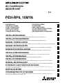 1
1
-
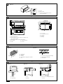 2
2
-
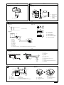 3
3
-
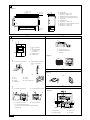 4
4
-
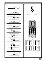 5
5
-
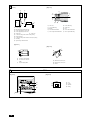 6
6
-
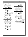 7
7
-
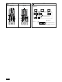 8
8
-
 9
9
-
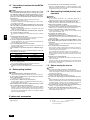 10
10
-
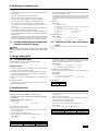 11
11
-
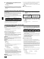 12
12
-
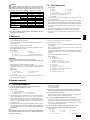 13
13
-
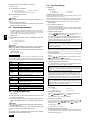 14
14
-
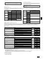 15
15
-
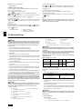 16
16
-
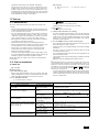 17
17
-
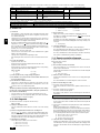 18
18
-
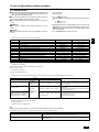 19
19
-
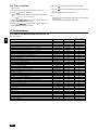 20
20
-
 21
21
-
 22
22


Mitsubishi PEH-10MYA Guida d'installazione
- Categoria
- Condizionatori d'aria a sistema split
- Tipo
- Guida d'installazione
- Questo manuale è adatto anche per
in altre lingue
Documenti correlati
Altri documenti
-
Mitsubishi Electric PUMY-P125 Guida d'installazione
-
Haier 4U30HS1ERA Guida d'installazione
-
-
-
Haier AC18CS1ERA Istruzioni per l'uso
-
LG LBNB2258QC Guida d'installazione
-
-
LG UV12H.NJ1 Manuale utente
-
LG CV18 Manuale utente
-
LG JRNU18GB2G3.APUNEJ Manuale del proprietario